jump cable MERCEDES-BENZ ML320 1997 Complete User Guide
[x] Cancel search | Manufacturer: MERCEDES-BENZ, Model Year: 1997, Model line: ML320, Model: MERCEDES-BENZ ML320 1997Pages: 4133, PDF Size: 88.89 MB
Page 1663 of 4133

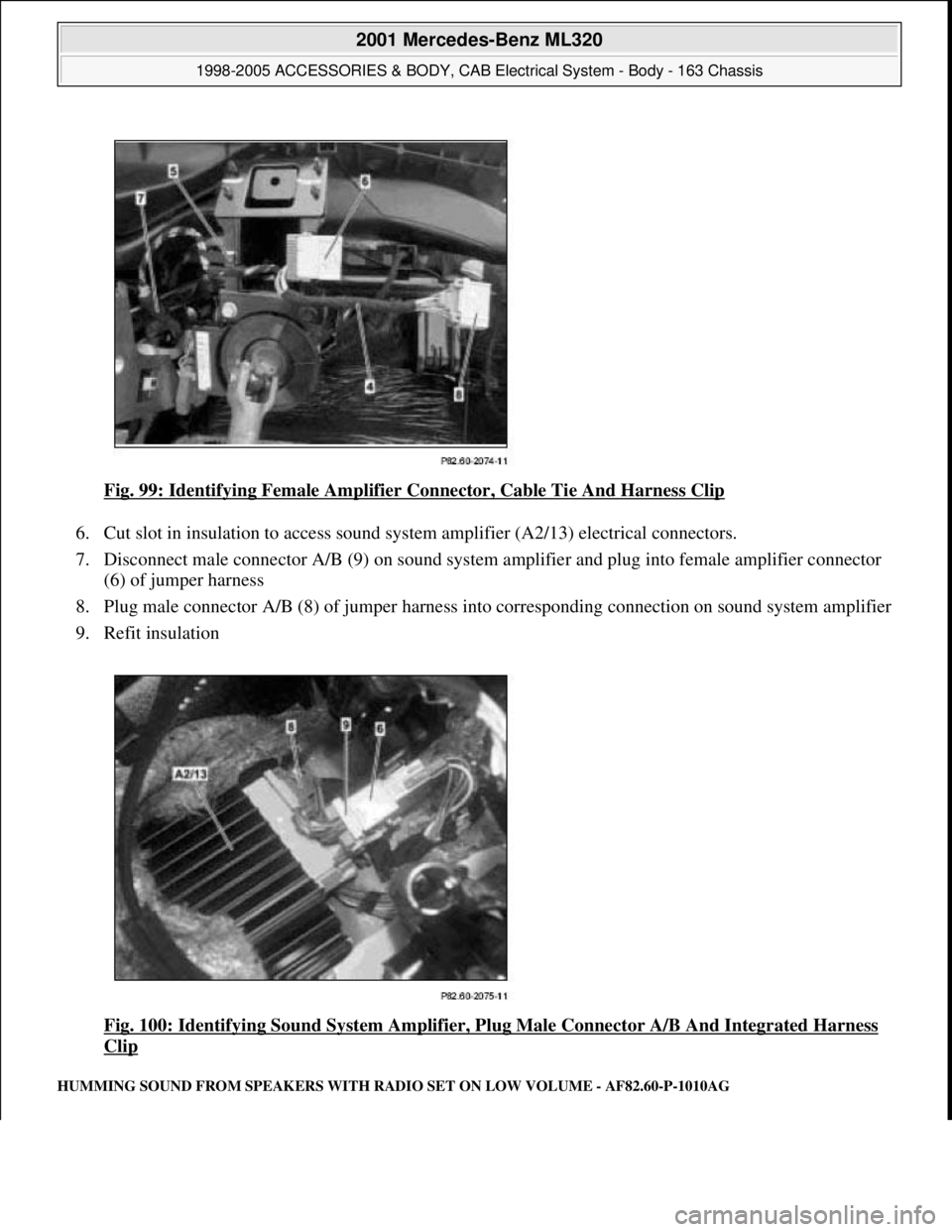
Fig. 99: Identifying Female Amplifier Connector, Cable Tie And Harness Clip
6. Cut slot in insulation to access sound system amplifier (A2/13) electrical connectors.
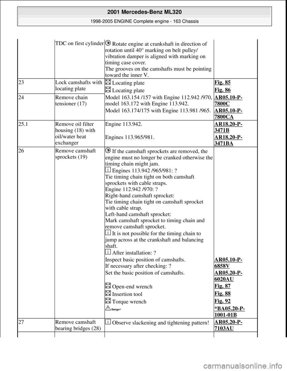
7. Disconnect male connector A/B (9) on sound system am plifier and plug into female amplifier connector
(6) of jumper harness
8. Plug male connector A/B (8) of jumper harness into corresponding connection on sound system amplifier
9. Refit insulation
Fig. 100: Identifying Sound System Amplifier, Plug Male Connector A/B And Integrated Harness
Clip
HUMMING SOUND FROM SPEAKERS WITH RADIO SET ON LOW VO LUME - AF82.60-P-1010AG
2001 Mercedes-Benz ML320
1998-2005 ACCESSORIES & BODY, CAB Electr ical System - Body - 163 Chassis
me
Saturday, October 02, 2010 3:30:06 PMPage 168 © 2006 Mitchell Repair Information Company, LLC.
Page 2444 of 4133

TDC on first cylinder Rotate engine at cra nkshaft in direction of
rotation until 40° marking on belt pulley/
vibration damper is al igned with marking on
timing case cover.
The grooves on the camshafts must be pointing
toward the inner V.
23Lock camshafts with
locating plate Locating plateFig. 85
Locating plateFig. 86
24Remove chain
tensioner (17)Model 163.154 /157 with Engine 112.942 /970,
model 163.172 with Engine 113.942.AR05.10-P-
7800C
Model 163.174/175 with Engine 113.981 /965.AR05.10-P-
7800CA
25.1Remove oil filter
housing (18) with
oil/water heat
exchangerEngine 113.942.AR18.20-P-
3471B
Engines 113.965/981.AR18.20-P-
3471BA
26Remove camshaft
sprockets (19) If the camshaft sprockets are removed, the
engine must no longer be cranked otherwise the
timing chain might jam.
Engines 113.942 /965/981: ?
Tie timing chain tight on both camshaft
sprockets with cable straps.
Engine 112.942 /970: ?
Right-hand camshaft sprocket:
Tie timing chain tight on camshaft sprocket
with cable strap.
Left-hand camshaft sprocket:
Mark camshaft sprocket to timing chain and
remove camshaft sprocket.
It is not possible for the timing chain to
jump across at the crankshaft and balancing
shaft.
After installation: ?
Inspect basic positi on of camshafts.
If necessary after checking: ?AR05.10-P-
6858V
Set the basic position of camshafts.AR05.20-P-
6020AU
Open-end wrenchFig. 87
Insertion toolFig. 88
Torque wrenchFig. 92
*BA05.20-P-
1001-01B
27Remove camshaft
bearing bridges (28) Observe slackening and tightening pattern!AR05.20-P-
7103AU
2001 Mercedes-Benz ML320
1998-2005 ENGINE Complete engine - 163 Chassis
me
Saturday, October 02, 2010 3:17:57 PMPage 88 © 2006 Mitchell Repair Information Company, LLC.
Page 3224 of 4133

blend air flap actuator motor.
6. Turn ignition off. Disconnect test cable from A/C push button control unit. Connect ohmmeter positive
lead to socket box terminal No. 1 and negative lead to terminal No. 8. Resistance should be 120 ohms.
7. If resistance is not as specified, check blend air flap actuator motor circuits. See WIRING DIAGRAMS
.
Repair as necessary. If circuits are okay, replace blend air flap actuator motor.
A/C Button
1. Connect socket box to A/C push button control unit and wiring harness. See CONNECTING TEST
EQUIPMENT . Connect voltmeter positive lead to socket box terminal No. 10 and negative lead to
terminal No. 9.
2. Turn ignition on. Depress A/C button switch to on position and set blower speed knob to position No. 4.
Ensure A/C button indicator is illuminated. Voltage should be less than one volt. Depress A/C button
switch to off position with A/C button indicator not illuminated or set blower speed knob to off position.
Voltage should be 11-14 volts.
3. If voltage is as specified, go to next step. If voltage is not as specified, check A/C button wiring harness
circuits. See WIRING DIAGRAMS
. Repair as necessary. If circuits are okay, replace A/C button
switch.
4. Turn ignition on. Depress A/C button switch to on position and set blower speed knob to position No. 4.
Ensure A/C button indicator is illuminated. Connect voltmeter positive lead to socket box terminal No. 4
and negative lead to terminal No. 9. Voltage should be more than 3.0 volts.
5. Connect Fused Jumper Wire (124 589 37 63 00) between socket box terminals No. 4 and 11. Depress A/C
button switch to on position and set blower speed knob to position No. 4. Ensure A/C button indicator is
illuminated. Measure voltage. Voltage should be less than one volt.
6. If voltage is not as specified, check A/C button wiring harness circuits. See WIRING DIAGRAMS
.
Repair as necessary. If circuits are okay, replace A/C button switch.
A/C Refrigerant Pressure Switch
1. Turn ignition off. Disconnect refrigerant pressure sensor connector. Turn ignition on. Connect voltmeter
positive lead to pressure sensor harness connector terminal "B" (Pink wire) and negative lead to terminal
"A" (Tan wire). Voltage should be 4.75-5.25 volts.
2. If voltage is as specified, replace A/C refrigerant pressure sensor. If voltage is not as specified, check
wiring harness between refrigerant pressure sensor and All Activity Module (AAM). See WIRING
DIAGRAMS . Repair as necessary. If circuits are okay, replace AAM and retest A/C system.
Outside Temperature Sensor
1. Connect socket box to A/C push button control unit and wiring harness. See CONNECTING TEST
EQUIPMENT . Turn ignition off. Connect ohmmeter positive lead to socket box terminal No. 12 and
negative lead to terminal No. 3.
2. Disconnect test cable from A/C push button control unit. See OUTSIDE TEMPERATURE SENSOR
RESISTANCE table. If resistance is not as specified, check wiring harness between outside temperature
sensor and A/C push button control unit. See WIRING DIAGRAMS
. Repair as necessary. If wiring
harness is okay, replace outside temperature sensor.
2001 Mercedes-Benz ML320
2000-01 MANUAL A/C-HEATER SYSTEMS ML 320, ML 430 & ML 55
me
Saturday, October 02, 2010 3:25:10 PMPage 13 © 2006 Mitchell Repair Information Company, LLC.