lights MERCEDES-BENZ ML320 1997 Complete User Guide
[x] Cancel search | Manufacturer: MERCEDES-BENZ, Model Year: 1997, Model line: ML320, Model: MERCEDES-BENZ ML320 1997Pages: 4133, PDF Size: 88.89 MB
Page 275 of 4133

225 Malfunction and indicator lamps
Te ch n ica l
data Instruments
and controlsOperation DrivingInstrument
cluster displayPractical hints Car care Index Brake pad wear indicator lamp
With the key in steering lock position 2, the
indicator lamp comes on and goes out when
the engine is running.
If the indicator lamp lights up during braking, this
indicates that the brake pads are worn down.
Have the brake system checked at your authorized
Mercedes-Benz Light Truck Center as soon as possible.FSS indicator
FSS indicator (Service A), see page 87.
FSS indicator (Service B), see page 87.
The symbols appear in the main odometer display field
prior to the next suggested service. Depending on
operating conditions throughout the year, the next
service is calculated and displayed in days or distance
remaining. See page 87 for notes on the flexible service
system (FSS).
Page 304 of 4133
254 Jump starting
Te ch n ica l
data Instruments
and controlsOperation DrivingInstrument
cluster displayPractical hintsCar care Index
Proceed as follows:
1. Position the vehicle with the charged battery so that
the jumper cables will reach, but never let the
vehicles touch. Make sure the jumper cables do not
have loose or missing insulation.
2. On both vehicles:
•Turn off engine and all lights and accessories,
except hazard warning flashers or work lights.
•Apply parking brake and shift selector lever to
position “P”.
Important!
3. Clamp one end of the first jumper cable to the
positive (+) under hood terminal of the discharged
battery and the other end to the positive (+) terminal
of the charged battery. Make sure the cable clamps
do not touch any other metal parts.
4. Clamp one end of the second jumper cable to the
grounded negative (–) terminal of the charged
battery and the final connection to the negative (–)
terminal of the discharged battery.Important!
5. Start engine of the vehicle with the charged battery
and run at high idle. Make sure the cables are not
on or near pulleys, fans, or other parts that move
when the engine is started. Allow the discharged
battery to charge for a few minutes. Start engine of
the disabled vehicle in the usual manner.
6. After the engine has started, remove jumper cables
by exactly reversing the above installation
sequence, starting with the last connection made
first. When removing each clamp, make sure that it
does not touch any other metal while the other end
is still attached.
Notes:
If engine does not run after several unsuccessful
starting attempts, have it checked at the nearest
authorized Mercedes-Benz Light Truck Center.
Excessive unburned fuel may damage the catalytic
converter.
Page 355 of 4133
305 Index
Te ch n ica l
data Instruments
and controlsOperation DrivingInstrument
cluster displayPractical hints Car careIndex Headlamp cleaning system ............................................ 94
Headlights ......................................................................... 90
Heated seats ..................................................................... 44
Hood ................................................................................. 231
Hooks ............................................................................... 133
IIdentification labels .......................................................285
Illuminated vanity mirrors ............................................113
Indicator lamps in the instrument cluster ................... 78
Infant and child restraint system
Installation ................................................................... 67
Infant and child restraint systems ................................ 65
Inflating the space-saver tire .......................................249
Information call
See Tele Aid ............................................................... 148
Instrument cluster ........................................................... 76
Activating display ....................................................... 80
Display illumination ................................................... 80
Indicator lamps ........................................................... 78
Malfunction and indicator lamps ........................... 218
Instrument lamps ............................................................ 80Instruments and controls ............................................... 18
Interior
General notes ............................................................. 114
Interior lighting .............................................................. 110
JJump starting ................................................................. 253KKeys, vehicle .....................................................................24LLamps, exterior .............................................................. 260
Adjusting headlamp aim ......................................... 268
Auxiliary fog lamp ............................................. 92, 264
Fog lamps .....................................................................93
Headlamp assembly ......................................... 261, 262
Headlamps .................................90, 261, 262, 268, 280
High mounted stop lamp ......................................... 267
License plate lamps ................................................. 267
Low and high beam ............................................90, 263
Page 495 of 4133
28
Central locking system
Te ch n ica l
data
Instruments
and controls Operation
Driving Instrument
cluster display Practical hints Car care Index
Locking:
Press transmit button ‹ once. All turn signal lamps
blink three times to indicate that the vehicle is locked
and the antitheft alarm is activated.
Notes:
If the turn signal lamps do not blink three times when
locking the vehicle, a door, the liftgate, or the hood is
not properly closed. Close the respective element and
lock the vehicle again with the remote control.
If the vehicle cannot be locked or unlocked by pressing
the transmit button, then it may be necessary to change
the batteries in the remote control or to synchronize the
remote control, see page 270 and page 271.
Unlocking the liftgate
Press transmit button Š to unlock the liftgate. This
also deactivates the antitheft alarm.
Important!
A minimum height clearance of 7 ft. (2.15 m) is
required to open the liftgate. Panic button
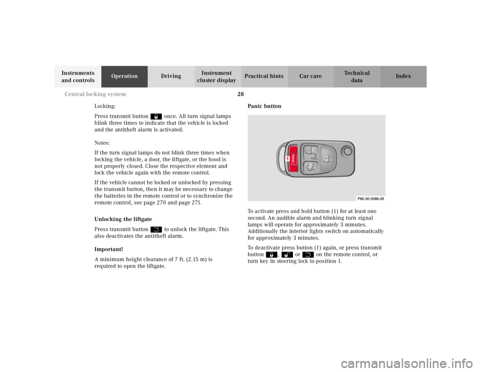
To activate press and hold button (1) for at least one
second. An audible alarm and blinking turn signal
lamps will operate for approximately 3 minutes.
Additionally the interior lights switch on automatically
for approximately 3 minutes.
To deactivate press button (1) again, or press transmit
button ‹, Œ orŠ on the remote control, or
turn key in steering lock to position 1.
Page 500 of 4133
33
Central locking system
Te ch n ica l
data
Instruments
and controls Operation
Driving Instrument
cluster display Practical hints Car care Index
Notes:
If doors are unlocked with the central locking switch
after activating the automatic central locking, and
neither door is opened, then the doors remain unlocked
even at vehicle speeds of approximately 9 mph
(15 km / h) or more.
If a door is opened from the inside at speeds of
approximately 9mph (15km/h) or less with the
automatic central locking activated, the door will again
be automatically locked at speeds of approximately
9 mph (15 km / h) or more.
Important!
When towing the vehicle, or with the vehicle on a
dynamometer test stand, please, note the following:
With the engine running, the vehicle doors will lock if
the left front wheel spins at vehicle speeds of
approximately 9 mph (15 km / h) or more.
To prevent vehicle door locks from locking, deactivate
the automatic central locking. Emergency unlocking in case of accident
The doors unlock automatically a short time after an
accident in which an airbag or emergency tensioning
retractor deploys (this is intended to aid rescue and
exit). However, the key must still be in the steering lock
position 1 or 2.
Additionally the hazard warning flashers turn on
automatically and the interior lights switch on for
approximately 30 minutes.
Page 502 of 4133
35
Antitheft alarm system
Te ch n ica l
data
Instruments
and controls Operation
Driving Instrument
cluster display Practical hints Car care Index
Antitheft alarm system
The indicator lamp is located in the center console.
The antitheft alarm is automatically armed or disarmed
with the remote control by locking or unlocking the
vehicle.
The antitheft alarm is armed within approximately
15 seconds after locking the vehicle with the remote
control.
A blinking lamp in the center console indicates that the
alarm is armed.
Notes:
Use of the key in the front door locks does not arm or
disarm the antitheft alarm system.
The alarm sounds when unlocking the driver’s door
with the mechanical key. Cancel alarm by turning key in
steering lock to position 1, or with the remote control by
pressing button Œ.
If the vehicle battery voltage falls below 10 volts, the
alarm is automatically canceled and the antitheft alarm
system is disarmed. When the voltage is above this
value again, the antitheft alarm system is armed again. Operation:
Once the alarm system has been armed, the turn signal
lamps will flash rapidly (approximately 3 minutes) and
the horn will sound intermittently (approximately
30 seconds) when someone:
• opens a door,
• opens the liftgate,
• opens the hood,
• breaks a window,
• attempts to raise the vehicle.
The alarm will stay on even if the activating element (a
door, for example) is immediately closed.
If the alarm stays on for more than 20 seconds, an
emergency call is initiated automatically. See Tele Aid
on page 148.
Note:
The alarm system will cycle three times when triggered.
The interior lights are automatically switched on when
the alarm comes on and go out when canceling the
alarm.
Page 511 of 4133
44
Seats
Te ch n ica l
data
Instruments
and controls Operation
Driving Instrument
cluster display Practical hints Car care Index
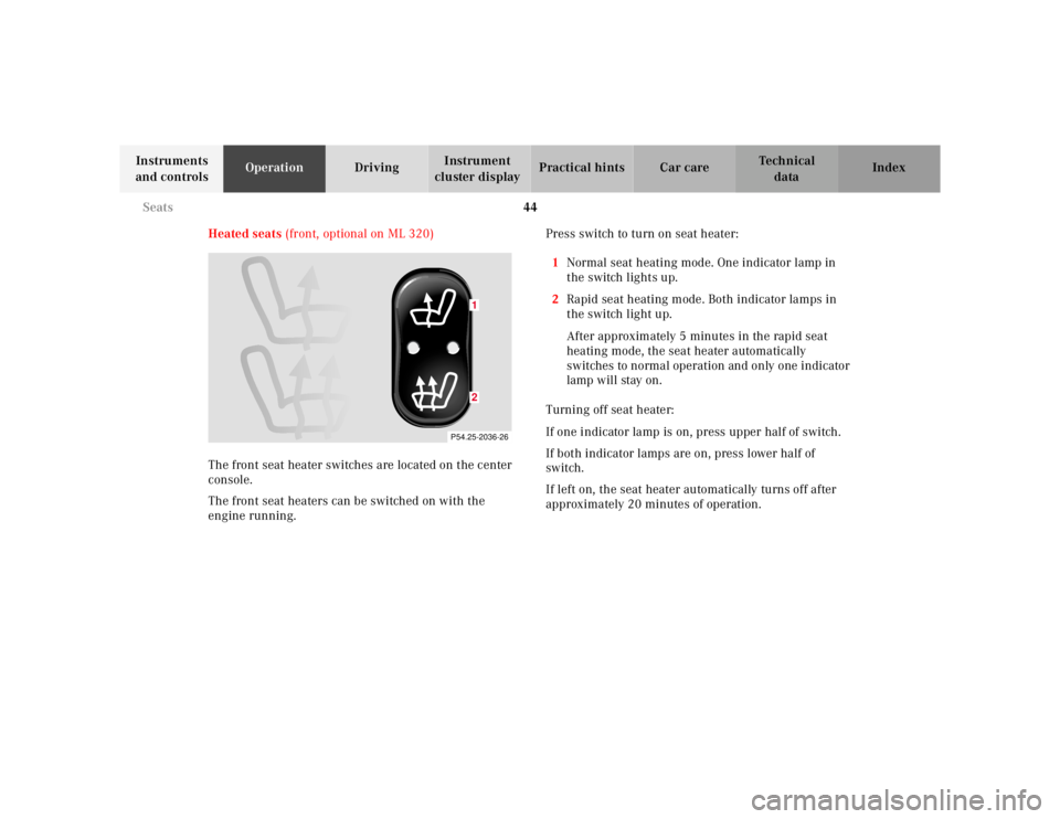
Heated seats (front, optional on ML 320)
The front seat heater switches are located on the center
console.
The front seat heaters can be switched on with the
engine running. Press switch to turn on seat heater:
1 Normal seat heating mode. One indicator lamp in
the switch lights up.
2 Rapid seat heating mode. Both indicator lamps in
the switch light up.
After approximately 5 minutes in the rapid seat
heating mode, the seat heater automatically
switches to normal operation and only one indicator
lamp will stay on.
Turning off seat heater:
If one indicator lamp is on, press upper half of switch.
If both indicator lamps are on, press lower half of
switch.
If left on, the seat heater automatically turns off after
approximately 20 minutes of operation.
P54.25-2036-26
12
Page 539 of 4133

72
Rear view mirrors
Te ch n ica l
data
Instruments
and controls Operation
Driving Instrument
cluster display Practical hints Car care Index
Automatic (optional on ML 320):
With the key in steering lock position 2 and the
automatic antiglare function activated, the mirror
reflection brightness responds to changes in light
sensitivity.
To a ctiva te:
Press button (1). The green indicator lamp in the rear
view mirror lights up. To deactivate:
Press button (1) again. The indicator lamp in the rear
view mirror goes out. The mirror brightness does not
respond to changes in light sensitivity.
Notes:
With gear selector lever in position “R”, or with the
interior lamps (except cargo compartment lamp)
switched on, the mirror brightness does not respond to
changes in light sensitivity.
The automatic antiglare function does not react, if
incoming light is not aimed directly at sensors in the
mirror.
Wa r n i n g !
In the case of an accident liquid electrolyte may
escape the mirror housing when the mirror glass
breaks.Electrolyte has an irritating effect. Do not allow the
liquid come into contact with eyes, skin, clothing,
or respiratory system. In cases it does, immediately
flush affected area with water, and seek medical
help if necessary.
Page 569 of 4133

102
Climate control
Te ch n ica l
data
Instruments
and controls Operation
Driving Instrument
cluster display Practical hints Car care Index
Windshield fogged up on outside.
Switch on wiper motor.
Set air distribution control switch to position d
or a .
Dust filter
Nearly all dust particles and pollen are filtered out
before outside air enters the passenger compartment
through the air distribution system.
Note:
Keep the air intake grille in front of windshield free of
snow and debris.
Climate control – OFF
To switch the climate control off, set air volume control
switch to position 0.
Switch off air conditioning mode œ. Control lamp in
button goes out. Air recirculation
This mode can be selected to temporarily reduce the
entry of annoying odors or dust into the vehicle’s
interior.
Outside air is not supplied to the vehicles’s interior.
To select, press O button. Indicator lamp in button
lights up.
To cancel, press O button again. Indicator lamp in
button goes out.
If the windows should fog up from the inside, switch
from recirculated air back to fresh air.
Page 633 of 4133

166
Automatic transmission
Te ch n ica l
data
Instruments
and controls Operation
Driving Instrument
cluster display Practical hints Car care Index
Driving
The selector lever is automatically locked while in
position “P”. To move the selector lever out of
position “P”, the service brake pedal must be firmly
depressed before the shift lock will release.
Shift selector lever to the desired position only when the
engine is idling normally and the service brake is
applied. Do not release the brake until ready to drive.
The vehicle may otherwise start creeping when the
selector lever is in drive or reverse position. Important!
After selecting any driving position from “N” or “P”,
wait a moment to allow the gear to fully engage before
accelerating, especially when the engine is cold.
Accelerator position
Partial throttle = early upshifting = normal acceleration
Full throttle = later upshifting = rapid acceleration
Kickdown (depressing the accelerator beyond full
throttle) = downshifting to a lower gear = maximum
acceleration. Once the desired speed is attained, ease up
on the accelerator – the transmission shifts up again.
Stopping
For brief stops, e.g. at traffic lights, leave the
transmission in gear and hold vehicle with the service
brake.
For longer stops with the engine idling, shift into “N”
or “P” and hold the vehicle with the service brake.
When stopping the vehicle on an uphill gradient, do not
hold it with the accelerator, use the brake. This avoids
unnecessary transmission heat build up.
Wa r n i n g !
It is dangerous to shift the selector lever out of “P”
or “N” if the engine speed is higher than idle speed.
If your foot is not firmly on the brake pedal, the
vehicle could accelerate quickly forward or in
reverse. You could lose control of the vehicle and
hit someone or something. Only shift into gear
when the engine is idling normally and when your
right foot is firmly on the brake pedal.