belt MERCEDES-BENZ ML320 1997 Complete Repair Manual
[x] Cancel search | Manufacturer: MERCEDES-BENZ, Model Year: 1997, Model line: ML320, Model: MERCEDES-BENZ ML320 1997Pages: 4133, PDF Size: 88.89 MB
Page 3829 of 4133

AR91.40-P-0681GH
Removing and installing rear seat belts
13.3.97
MODELS
163.136 /154 /172 up to 31.8.99
P91.40-0360-06
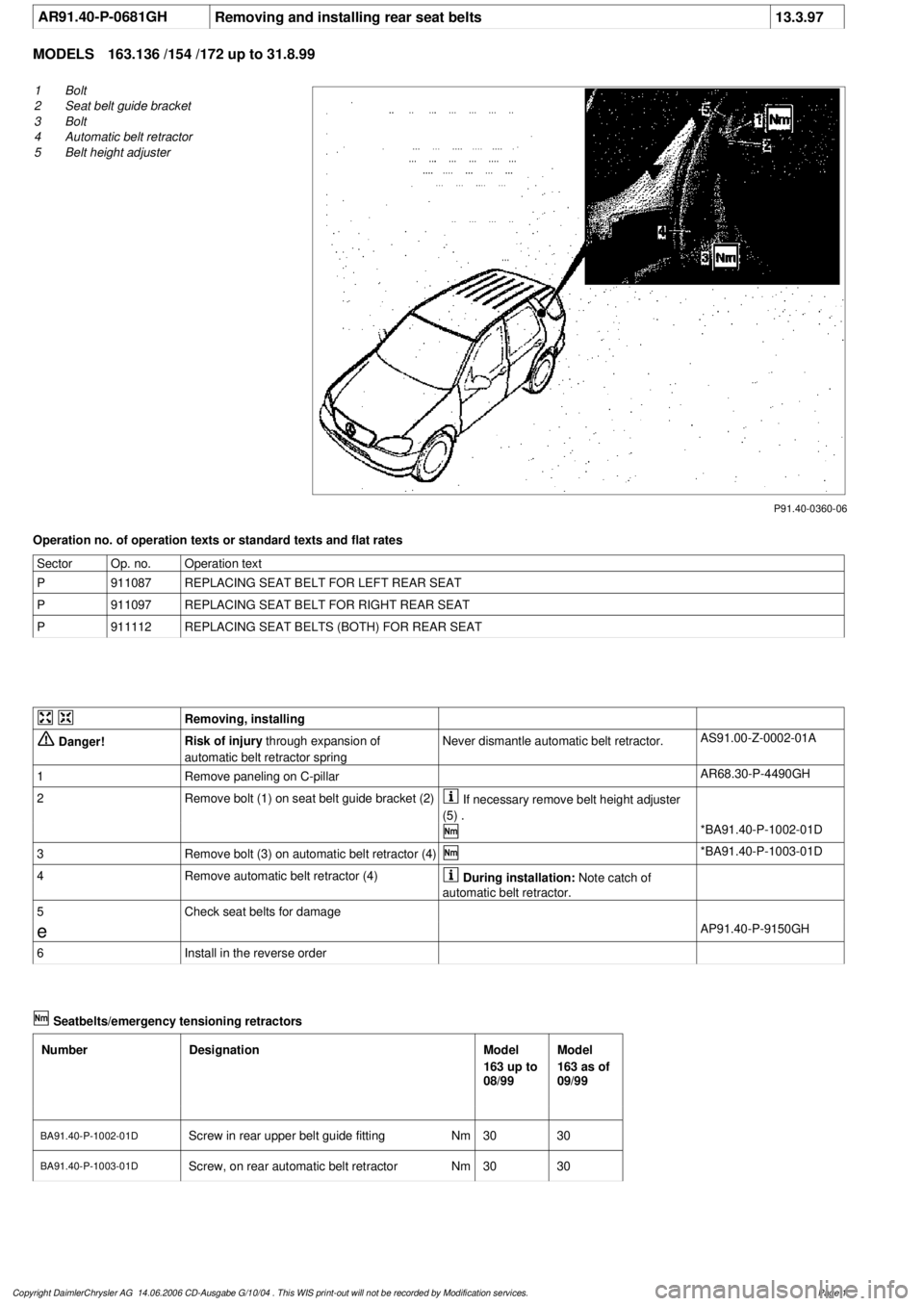
1
Bolt
2
Seat belt guide bracket
3
Bolt
4
Automatic belt retractor
5
Belt height adjuster
Operation no. of operation texts or standard texts and flat rates
Sector
Op. no.
Operation text
P
911087
REPLACING SEAT BELT FOR LEFT REAR SEAT
P
911097
REPLACING SEAT BELT FOR RIGHT REAR SEAT
P
911112
REPLACING SEAT BELTS (BOTH) FOR REAR SEAT
Removing, installing
Danger!
Risk of injury
through expansion of
automatic belt retractor spring
Never dismantle automatic belt retractor.
AS91.00-Z-0002-01A
1
Remove paneling on C-pillar
AR68.30-P-4490GH
2
Remove bolt (1) on seat belt guide bracket (2)
If necessary remove belt height adjuster
(5) .
*BA91.40-P-1002-01D
3
Remove bolt (3) on automatic belt retractor (4)
*BA91.40-P-1003-01D
4
Remove automatic belt retractor (4)
During installation:
Note catch of
automatic belt retractor.
5
Check seat belts for damage
e
AP91.40-P-9150GH
6
Install in the reverse order
Seatbelts/emergency tensioning retractors
Number
Designation
Model
163 up to
08/99
Model
163 as of
09/99
BA91.40-P-1002-01D
Screw in rear upper belt guide fitting
Nm
3030
BA91.40-P-1003-01D
Screw, on rear automatic belt retractorNm
3030
Copyright DaimlerChrysler AG 14.06.2006 CD-Ausgabe G/10/04 . This WIS print-out will not be recorde
d by Modification services.
Page 1
Page 3833 of 4133

SI91.60-P-0002A
Service information on immobilization of a passenger-side airbag where a
rearward mounted (reboard) child seat is fitted
17.3.99
MODEL
124, 126, 129, 140, 163, 168, 170, 202, 203, 208, 210, 215, 220, 463
Modification notes
18.11.00
Supersedes Service Information SI91.60-P-0002A dated
15.11.00
Remove the SI SI91.60-P-0002A from your file
It is recommended to place the child seat in the rear area if
possible.
If, in exceptional cases, the owner wishes a rearward mounted child
seat to be expressly attached on the front passenger seat, the front
passenger airbag should be immobilized.
As a general rule, there is no approval for immobilizing the front
passenger airbag on models fitted with ACSR, which is visible from
the "airbag OFF" indicator light in the center console. On such
models, an MB child seat with ACSR should be used for safety and
cost reasons.
-----------------------------------------------------------------------------------------
On models fitted with seat belt force limiter, it is essential for
safety reasons to
D
program the front passenger ETR to "NO".
D
unplug the connector at the front passenger ETR.
No provision is made for immobilizing the seat occupied
recognition, the automatic child seat recognition (ACSR), as well as
the side airbag and window airbag.
In the event that it is necessary to immobilize the seat occupied
recognition and automatic child seat recognition (ACSR), for example
if a Recaro seat is installed, this can be carried out in exceptional
cases after agreement has been obtained from GSP/SPS, tel. 07031
/ 90 - 81815.
-----------------------------------------------------------------------------------------
After immobilizing the front passenger airbag or additionally the
ETR, it is essential to
D
have the customer sign the confirmation after immobilization.
D
affix a sticker at a clearly visible point in the area of the front
passenger airbag.
D
affix a sticker in the Owner's Manual, in the section Airbag.
Carry out the remaining procedure as stated below.
-----------------------------------------------------------------------------------------
Deactivation can be reversed at any time.
Immobilization and re-activation must be entered in the
vehicle documents!
The vehicle should be presented in such a case to a technical
inspection center (DEKRA, TÜV). The completed confirmation
should be submitted to the vehicle registration authorities for
entry.
-----------------------------------------------------------------------------------------
Perform version coding / procedure
Model
Version
Coding with HHT
2)
or STAR Diagnosis tool (DAS)
Unplug
connector of
passenger side
airbag
3)
Unplug
connector of
passenger side
emergency
tensioning
retractor
Insert
replacement resistor
3)
Passenger-side
airbag
NO
Passenger side
emergency
tensioning
retractor NO
124
All
--X-X
126
All
--X-X
129
up to 06/93
--X-X
129
as of 07/93 without ACSR
X-X--
140
up to 06/93
--X-X
140
as of 07/93 without ACSR
X-X--
140
as of 07/93 with ACSR
1)
-----
163
up to VIN 145263
--X-X
163
as of VIN 145264
-----
168
All
-----
170
without ACSR
XXXX-
170
with ACSR
1)
-----
202
without seat belt force limiter
X-X--
202
as of 06/97
4)
XXXX-
202
with ACSR
1)
-----
203
All
-----
208
All
-----
210
without ACSR
XXXX-
210
with ACSR
1)
-----
215
All
-----
220
All
-----
Copyright DaimlerChrysler AG 14.06.2006 CD-Ausgabe G/10/04 . This WIS print-out will not be recorde
d by Modification services.
Page 1
Page 3834 of 4133

463
All
-----
1)
Recognition: existing "airbag Off" warning light in center
console.
2)
With HHT functions menu point 5 Coding Reboard child seat. If
only the passenger side airbag is de-activated, then program
menu point Vehicle equipment.
3)
Depending on model and version, unplug one or two
connectors at the passenger side airbag and insert the
corresponding replacement resistors.
4)
Without ACSR, with seat belt force limiter.
Immobilizing passenger side airbag certificate
Model 124, 126, 129, 140, 163 up to VIN
145263, 170, 202, 210
Have customer sign certificate after
immobilization
OF91.60-P-1000-01A
Cancel immobilization
D
To re-activate the passenger side airbag remove the ignition
resistor at the cable.
D
Fit together connector at passenger side airbag.
D
Fit together connector at passenger side ETR (on models fitted
with seat belt force limiter).
D
Use HHT or STAR Diagnosis tool (DAS) to re-program
passenger side airbag and passenger side ETR in the SRS
control module to "YES".
D
Remove sticker on passenger side airbag and render invalid in
Owner's Manual.
D
Complete re-activation on certificate after immobilization.
D
If re-activated, delete de-activation in vehicle documents.
Parts ordering notes
Part no.
Designation
Quantity
140 868 00 50
Ignition resistor (replacement resistor)
as required
140 817 15 20
Sticker (without seat belt force limiter)
2
210 817 20 20
Sticker (with seat belt force limiter)
2
Copyright DaimlerChrysler AG 14.06.2006 CD-Ausgabe G/10/04 . This WIS print-out will not be recorde
d by Modification services.
Page 2
Page 3883 of 4133

2001-04 STARTING & CHARGING SYSTEMS Starters - 163 Chassis
MODEL IDENTIFICATION
MODEL IDENTIFICATION
DESCRIPTION
Starter is a brush-type, series-wound el ectric motor with an overrunning clutch. Field frame contains field coils
and is enclosed by commutator/drive bushing end frame, which carries pole shoes. A splined armature shaft
carries drive assembly.
TROUBLE SHOOTING
BASIC TROUBLESHOOTING
If starter is noisy, the cause could be bent or damaged gear tooth chamfers on ring gear. This cannot be seen
with starter installed in ve hicle. Activate starter without switching ignition on. Me tallic noise should not be
heard. If noise is he ard, replace ring gear.
PRELIMINARY INSPECTION
Verify customer complaint by operating system. Visually inspect for obvious signs of mechanical and electrical
damage. Check generator belt tension and condition. Ensure that battery voltage is within specifications. Inspect
for blown fuses and damaged relays. For fuse and/or relay identification, see WIRING DIAGRAMS
.
WARNING:
Vehicles are equipped with air bag supplemental restraint system. Before
attempting any repairs involving steer ing column, instrument panel or
related components, see SERVICE PRECAUTIONS (or AIR BAG SAFETY
PRECAUTIONS) and DISABLING & ACTIVATING AIR BAG SYSTEM in
appropriate AIR BAG REST RAINT SYSTEMS article.
NOTE: When the battery is di sconnected, vehicle computer and memory system may
lose data. Driveability problems may exist until computer systems have
completed a relearn cycle. Radio will not operate until coded. Obtain code card
from customer.
NOTE: The following table identifies mo dels applicable to this article.
ModelChassisEngine Number
ML430 (2001)163.172113.942
ML320 (2001-03)163.154112.942
ML55 AMG (2001-03)163.174113.981
ML500 (2002-04)163.175113.965
ML350 (2003-04)163.157112.970
2001 Mercedes-Benz ML320
2001-04 STARTING & CHARGING SYSTEMS Starters - 163 Chassis
2001 Mercedes-Benz ML320
2001-04 STARTING & CHARGING SYSTEMS Starters - 163 Chassis
me
Saturday, October 02, 2010 3:19:47 PMPage 1 © 2006 Mitchell Repair Information Company, LLC.
me
Saturday, October 02, 2010 3:19:50 PMPage 1 © 2006 Mitchell Repair Information Company, LLC.
Page 3896 of 4133

AR91.60-P-0660GH
Removing and installing airbag unit on steering wheel
27.2.01
MODEL
163.113 /128 /136 /154 /157 /172 /174 /175
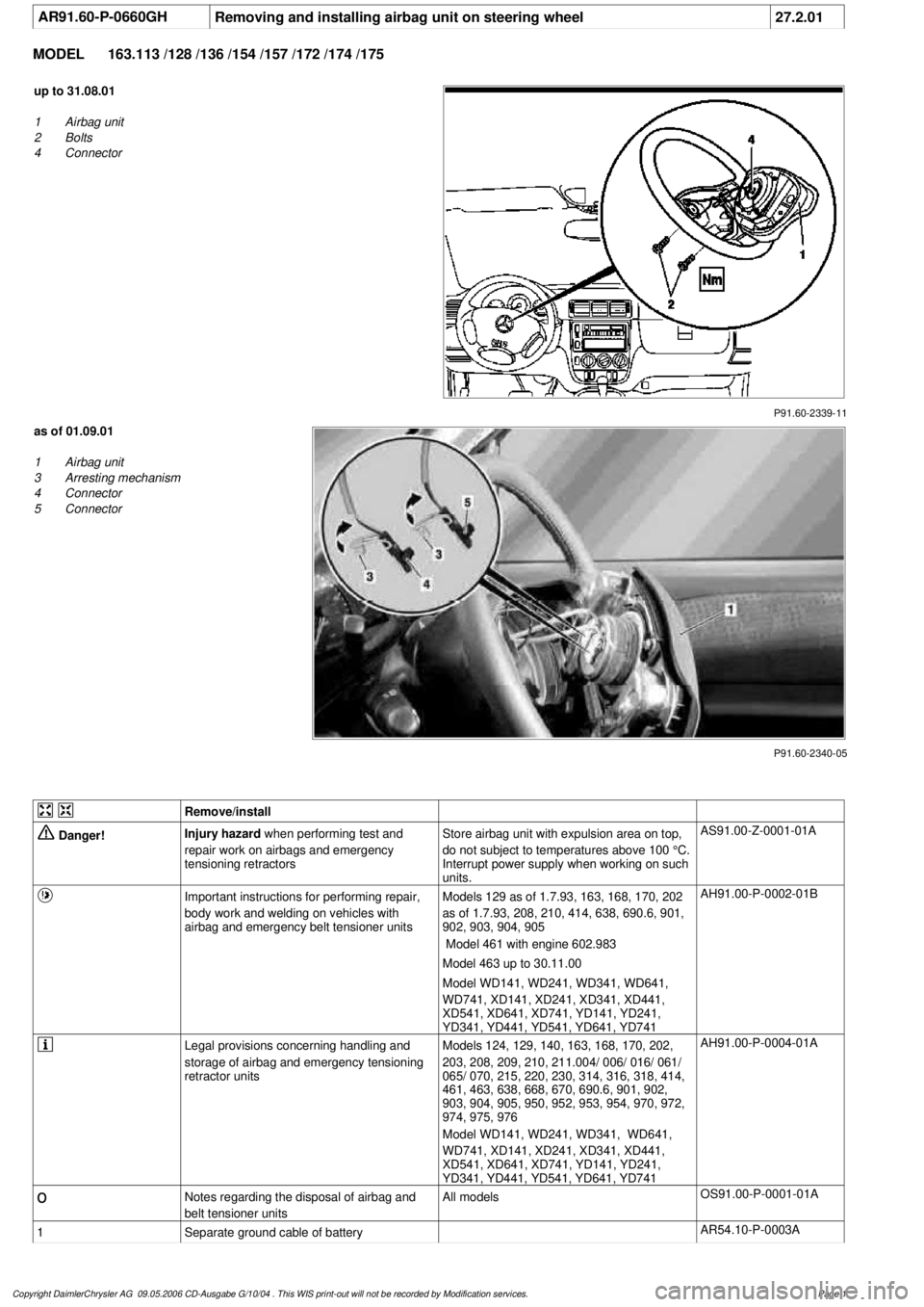
P91.60-2339-11
up to 31.08.01
1
Airbag unit
2
Bolts
4
Connector
P91.60-2340-05
as of 01.09.01
1
Airbag unit
3
Arresting mechanism
4
Connector
5
Connector
Remove/install
Danger!
Injury hazard
when performing test and
repair work on airbags and emergency
tensioning retractorsStore airbag unit with expulsion area on top,
do not subject to temperatures above 100 °C.
Interrupt power supply when working on such
units.
AS91.00-Z-0001-01A
Important instructions for performing repair,
body work and welding on vehicles with
airbag and emergency belt tensioner units
Models 129 as of 1.7.93, 163, 168, 170, 202
as of 1.7.93, 208, 210, 414, 638, 690.6, 901,
902, 903, 904, 905
Model 461 with engine 602.983
Model 463 up to 30.11.00
Model WD141, WD241, WD341, WD641,
WD741, XD141, XD241, XD341, XD441,
XD541, XD641, XD741, YD141, YD241,
YD341, YD441, YD541, YD641, YD741
AH91.00-P-0002-01B
Legal provisions concerning handling and
storage of airbag and emergency tensioning
retractor units
Models 124, 129, 140, 163, 168, 170, 202,
203, 208, 209, 210, 211.004/ 006/ 016/ 061/
065/ 070, 215, 220, 230, 314, 316, 318, 414,
461, 463, 638, 668, 670, 690.6, 901, 902,
903, 904, 905, 950, 952, 953, 954, 970, 972,
974, 975, 976
Model WD141, WD241, WD341, WD641,
WD741, XD141, XD241, XD341, XD441,
XD541, XD641, XD741, YD141, YD241,
YD341, YD441, YD541, YD641, YD741
AH91.00-P-0004-01A
o
Notes regarding the disposal of airbag and
belt tensioner units
All models
OS91.00-P-0001-01A
1
Separate ground cable of battery
AR54.10-P-0003A
Copyright DaimlerChrysler AG 09.05.2006 CD-Ausgabe G/10/04 . This WIS print-out will not be recorde
d by Modification services.
Page 1
Page 3960 of 4133

AD54.30-P-5000-03A
Directly controlled display instruments
troubleshooting chart IC
Directly controlled display instruments or indicator
lamp/warning message:
D
Outside temperature indicator
D
Fuel gauge
D
Oil pressure gauge (models 129 and 140 only)
D
Left turn signal indicator lamp
D
Right turn signal indicator lamp
D
High beam indicator lamp
D
Fuel reserve indicator lamp
D
Airbag SRS indicator lamp/MIL
D
AIRBAG OFF indicator lamp (only model 163 except
I )
D
Low brake fluid level/parking brake indicator lamp (only brake
fluid direct)
(both functions via CAN on model 163)
D
Low windshield washer fluid level indicator lamp (except
models 163 and 168)
D
Low ECL indicator lamp (except models 163 and 168)
D
Generator charge indicator lamp
D
Seat belt reminder lamp
D
Seat belt/backrest lock reminder lamp
D
Exterior lamp failure indicator lamp
D
Hydraulic fluid level indicator lamp (models 202 and 210 only)
D
ADS MIL, suspension
D
Turn signal clicking
D
Seat belt reminder lamp
D
Light reminder lamp
D
Key reminder lamp
D
Soft top reminder lamp (model 170 only)
D
Steering lock warning lamp (
I )
Copyright DaimlerChrysler AG 05.06.2006 CD-Ausgabe G/10/04 . This WIS print-out will not be recorde
d by Modification services.
Page 1
Page 3983 of 4133

10
Remove edge guard for tilting/sliding roof
cutout
11
Release upper right B-pillar paneling
12
Remove covers at lower rear seat
Do NOT remove center cover for lower
40% seat. Do NOT reinstall curtain on 60%
front bench seat.
f
Remove and install cover on bottom of rear
seat
AR91.12-P-1100GH
13
Release side shade at the 60% bench
Fold shade upward so that the working
area is not obstructed.
14
Remove 40% rear seat
f
Remove and install bench
AR91.12-P-1010GI
Torx bit set
*000589011000
Install
15
Retrofit central interface module (1)
AZ82.60-P-0004-01A
16
Insert antenna cable for FM modulator (6) into
vehicle antenna cable (7)
17
Cover connector with self-adhesive foamed
material (8)
18
Plug remaining antenna cable of FM
modulator (9) into radio
19
Install radio (A2)
f
Remove/install radio
AR82.60-P-7502EA
20
Retrofit video monitor (2) and wiring harness
of video monitor (C)
With
glass version of electric sliding/tilting
roof, code 414a.
AZ82.60-P-0004-02A
Except
glass version of electric
sliding/tilting roof, code 414a.
AZ82.60-P-0004-02B
21
Secure upper right B-pillar paneling
Ensure that the lugs of the seat belt height
adjustment are located correctly in the recess
clearance of the paneling.
22
Install right front handle
23
Install right sun visor
f
Remove/install sun visor
AR68.60-P-5480GH
24
Install right front A-pillar cover
f
Remove/install paneling on A-pillar
AR68.30-P-4050GH
25
Re-secure upper area of rubber door seal
26
Route wiring harness of video/DVD player
(B), additional interface module (4) and wiring
harness of video monitor (C) later
Up to VIN A289564, X754619.
AZ82.60-P-0004-03A
As of VIN A289565, X754620.
AZ82.60-P-0004-03B
27
Retrofit auxiliary interface module (4) in
center console
Up to VIN A289564, X754619.
AZ82.60-P-0004-04A
As of VIN A289565, X754620.
AZ82.60-P-0004-04B
28
Install center console insulating mat
29
Install center console
f
Remove/install center console
AR68.20-P-2000GH
30.1
Plug in plug of additional interface module
and secure the wiring harness of the
additional interface module (10) to the clip
(11) together with the wiring harness of the
rear power windows in the center console
Up to VIN A289564, X754619.
30.2
Insert auxiliary interface module (13)
connector and route between center console
mount (14) and center console.
As of VIN A289565, X754620.
31.1
Secure auxiliary interface module plug in the
left rear corner of the ashtray housing using
self-adhesive foamed material (12)
Up to VIN A289564, X754619.
32
Open ashtray and cup holder and close to
check correct function
33
Attach side shade of the 60% bench
34.1
Retrofit video player (3)
AZ82.60-P-0004-05A
*BA91.12-P-1005-03A
*BA91.12-P-1008-03A
34.2
Retrofit DVD player
AZ82.60-P-0005-01GH
35
Install 40% rear seat
f
Remove and install bench
AR91.12-P-1010GI
Torx bit set
*000589011000
Copyright DaimlerChrysler AG 09.05.2006 CD-Ausgabe G/10/04 . This WIS print-out will not be recorde
d by Modification services.
Page 2
Page 3986 of 4133

AR20.40-P-5660C
Remove/install viscous fan clutch
12.6.96
ENGINE
112 in MODEL 210, 202, 163.154 /157, 129
ENGINE
113 in MODEL 210, 208, 202, 163.172, 129
ENGINE
112.945 in MODEL 463.209 /232 /233 /244 /245 /250
ENGINE
113.962 in MODEL 463.206 /240 /241 /247 /248 /249 /254
ENGINE
113.982 in MODEL 463.243 /246
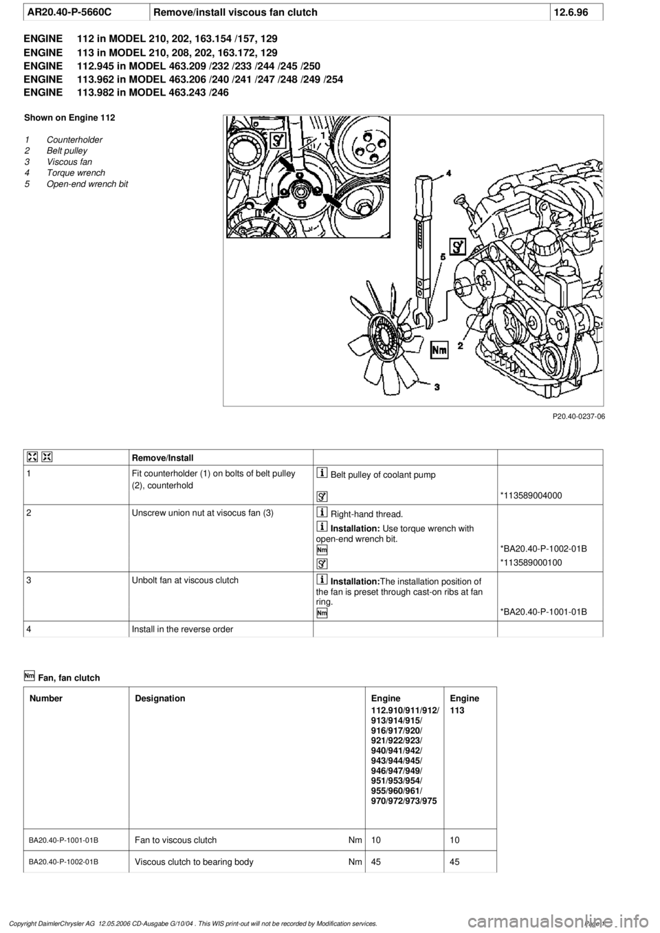
P20.40-0237-06
Shown on Engine 112
1
Counterholder
2
Belt pulley
3
Viscous fan
4
Torque wrench
5
Open-end wrench bit
Remove/Install
1
Fit counterholder (1) on bolts of belt pulley
(2), counterhold
Belt pulley of coolant pump
*113589004000
2
Unscrew union nut at visocus fan (3)
Right-hand thread.
Installation:
Use torque wrench with
open-end wrench bit.
*BA20.40-P-1002-01B
*113589000100
3
Unbolt fan at viscous clutch
Installation:
The installation position of
the fan is preset through cast-on ribs at fan
ring.
*BA20.40-P-1001-01B
4
Install in the reverse order
Fan, fan clutch
Number
Designation
Engine
112.910/911/912/
913/914/915/
916/917/920/
921/922/923/
940/941/942/
943/944/945/
946/947/949/
951/953/954/
955/960/961/
970/972/973/975
Engine
113
BA20.40-P-1001-01B
Fan to viscous clutch
Nm
1010
BA20.40-P-1002-01B
Viscous clutch to bearing body
Nm
4545
Copyright DaimlerChrysler AG 12.05.2006 CD-Ausgabe G/10/04 . This WIS print-out will not be recorde
d by Modification services.
Page 1
Page 3988 of 4133

AD54.30-P-3000-02A
Warning buzzer function check IC
Warning buzzer
D
Light reminder and parking brake reminder
D
Key reminder
I
D
Seat belt reminder
for approx. 6 s
I
,
M
,
H
and Korea
for approx. 12 s
G
The warning tone is interrupted as soon as the seat belt buckle is
inserted.
D
Warning tone for a shortage of oil
D
Vehicle speed warning
G
> 120 km/h, v-limit warning (cruise
control)
D
In addition the symbol for vehicle speed warning appears in the
instrument cluster with multi-function display.
D
On model 163 a warning tone sounds for approx. 5 seconds if the
CAN signal is unusable.
D
Model 168 with automatic clutch system features an audible gear
warning.
It sounds if a gear is engaged at the same time as the driver's
door is opened. Brake and accelerator pedal must not be
operated.
Copyright DaimlerChrysler AG 05.06.2006 CD-Ausgabe G/10/04 . This WIS print-out will not be recorde
d by Modification services.
Page 1