horn MERCEDES-BENZ ML320 1997 Complete Owner's Manual
[x] Cancel search | Manufacturer: MERCEDES-BENZ, Model Year: 1997, Model line: ML320, Model: MERCEDES-BENZ ML320 1997Pages: 4133, PDF Size: 88.89 MB
Page 3898 of 4133

AR46.10-P-0200GH
Removing, installing contact spiral
1.3.97
MODEL
163.113 /128 /136 /154 /157 /172 /174 /175
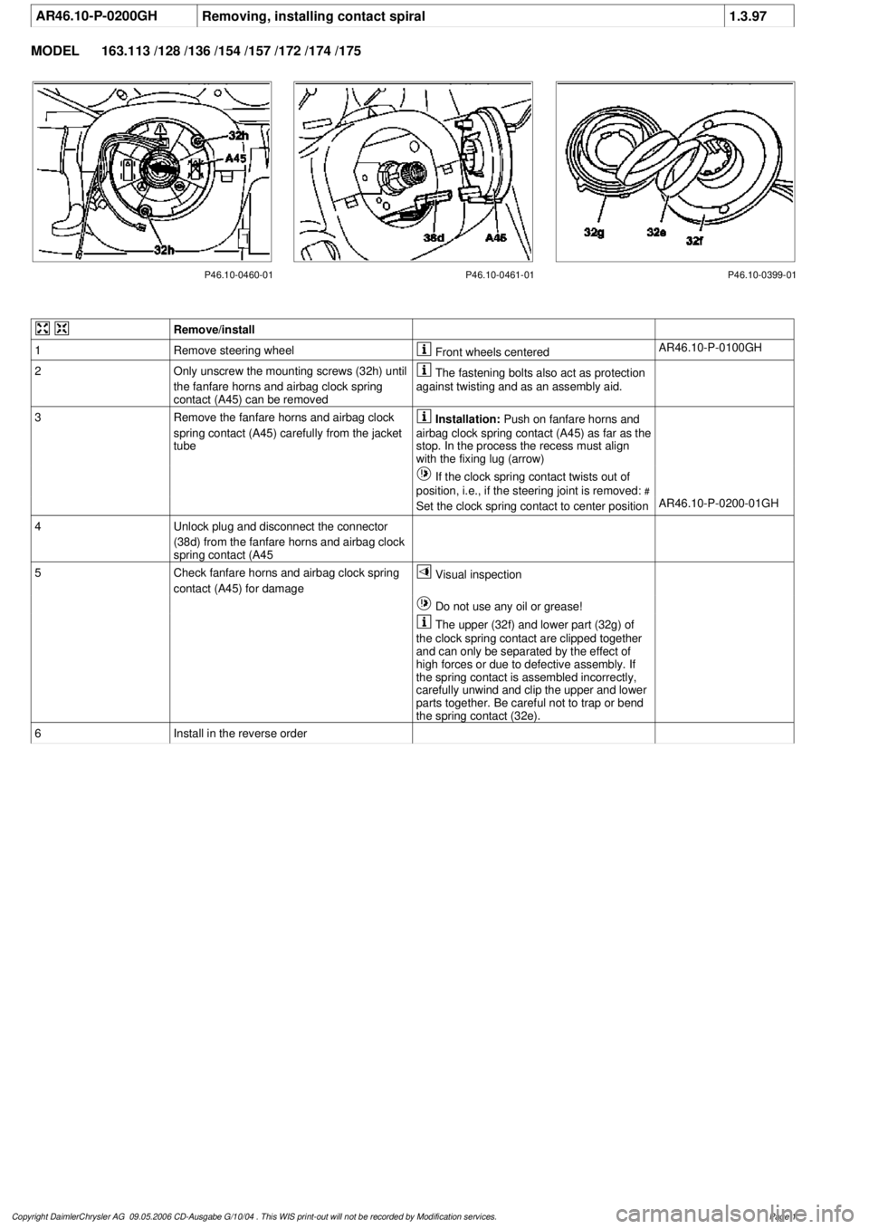
P46.10-0460-01 P46.10-0461-01 P46.10-0399-01
Remove/install
1
Remove steering wheel
Front wheels centered
AR46.10-P-0100GH
2
Only unscrew the mounting screws (32h) until
the fanfare horns and airbag clock spring
contact (A45) can be removed
The fastening bolts also act as protection
against twisting and as an assembly aid.
3
Remove the fanfare horns and airbag clock
spring contact (A45) carefully from the jacket
tube
Installation:
Push on fanfare horns and
airbag clock spring contact (A45) as far as the
stop. In the process the recess must align
with the fixing lug (arrow)
If the clock spring contact twists out of
position, i.e., if the steering joint is removed:
#
Set the clock spring contact to center position
AR46.10-P-0200-01GH
4
Unlock plug and disconnect the connector
(38d) from the fanfare horns and airbag clock
spring contact (A45
5
Check fanfare horns and airbag clock spring
contact (A45) for damage
Visual inspection
Do not use any oil or grease!
The upper (32f) and lower part (32g) of
the clock spring contact are clipped together
and can only be separated by the effect of
high forces or due to defective assembly. If
the spring contact is assembled incorrectly,
carefully unwind and clip the upper and lower
parts together. Be careful not to trap or bend
the spring contact (32e).
6
Install in the reverse order
Copyright DaimlerChrysler AG 09.05.2006 CD-Ausgabe G/10/04 . This WIS print-out will not be recorde
d by Modification services.
Page 1
Page 3899 of 4133

AR46.10-P-0100GHRemoving and installing steering wheel
1.3.97
MODEL
163.113 /128 /136 /154 /157 /172 /174 /175
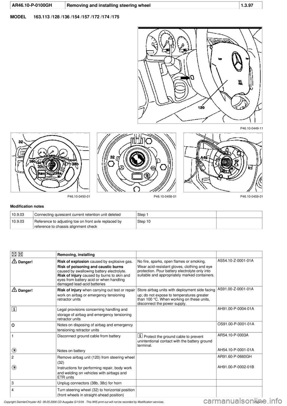
P46.10-0449-11
P46.10-0450-01 P46.10-0458-01 P46.10-0459-01
Modification notes
10.9.03
Connecting quiescent current retention unit deleted
Step 1
10.9.03
Reference to adjusting toe on front axle replaced by
reference to chassis alignment check
Step 10
Removing, installing
Danger!
Risk of explosion
caused by explosive gas.
Risk of poisoning and caustic burns
caused by swallowing battery electrolyte.
Risk of injury
caused by burns to skin and
eyes from battery acid or when handling
damaged lead-acid batteries
No fire, sparks, open flames or smoking.
Wear acid-resistant gloves, clothing and eye
protection. Pour battery electrolyte only into
suitable and appropriately marked containers.
AS54.10-Z-0001-01A
Danger!
Risk of injury
when carrying out test or repair
work on airbag or emergency tensioning
retractor units
Store airbag units with deployment side facing
up; do not expose to temperatures greater
than 100 °C. When working on these units,
disconnect the power supply.
AS91.00-Z-0001-01A
Legal provisions concerning handling and
storage of airbag and emergency tensioning
retractor units
AH91.00-P-0004-01A
o
Notes on disposing of airbag and emergency
tensioning retractor units
OS91.00-P-0001-01A
1
Disconnect ground cable from battery
Protect the ground cable to prevent
unintentional contact with the battery ground
terminal.
AR54.10-P-0003A
Notes on battery
AH54.10-P-0001-01A
2
Remove airbag unit (120) from steering wheel
(32)
AR91.60-P-0660GH
Instructions for performing repair, body work
and welding on vehicles with airbags and
ETR units
AH91.00-P-0002-01B
3
Unplug connectors (38b, 38c) for horn
4
Turn steering wheel (32) to horizontal position
(front wheels in straight-ahead position)
Copyright DaimlerChrysler AG 09.05.2006 CD-Ausgabe G/10/04 . This WIS print-out will not be recorde
d by Modification services.
Page 1
Page 3900 of 4133

5
Remove key and engage steering lock
6
Unscrew bolt (32c)
Hold the steering wheel (32).
Installation:
Replace bolt (32c).
*BA46.10-P-1001-02A
7
Pull off steering wheel (32)
Pass cables carefully through the openings.
Installation:
Align recesses of the splines
in the steering wheel with the markings on the
steering shaft (arrows).
8
Check fanfare horns and airbag clock spring
contact (A45) for damage
The clock spring contact must not be
turned while the steering wheel is removed
otherwise it will be damaged.
Visual inspection, replace clock spring
contact if necessary:
#
Removing and installing clock spring contact
AR46.10-P-0200GH
9
Install in the reverse order
10
Carry out road test
Tests during the road test:
Turn signal canceling:
When the steering wheel is offset by
more than 1 tooth, satisfactory resetting of the
turn signal is no longer guaranteed.
Airbag indicator lamp:
The SRS indicator lamp must not light up
on full steering lock in both directions.
Steering wheel position:
If the steering wheel is crooked, adjust it
by max. 1 tooth. If the difference is greater:
#
Check toe on front axle and adjust if
necessary, see:
#
Performing chassis alignment check
AR40.20-P-0200A
Steering wheel
Number
Designation
Model 163
BA46.10-P-1001-02A
Bolt, steering wheel to steering shaft
Nm
80
Copyright DaimlerChrysler AG 09.05.2006 CD-Ausgabe G/10/04 . This WIS print-out will not be recorde
d by Modification services.
Page 2
Page 4057 of 4133

Fig. 29: Headlights Circuit, W/O Xenon Lamps (2 of 2)
HORN
2001 Mercedes-Benz ML320
2001 SYSTEM WIRING DIAGRAMS Mercedes-Benz - ML320
me
Saturday, October 02, 2010 3:27:59 PMPage 59 © 2006 Mitchell Repair Information Company, LLC.
Page 4059 of 4133

Fig. 30: Horn Circuit
INSTRUMENT CLUSTER
2001 Mercedes-Benz ML320
2001 SYSTEM WIRING DIAGRAMS Mercedes-Benz - ML320
me
Saturday, October 02, 2010 3:27:59 PMPage 61 © 2006 Mitchell Repair Information Company, LLC.