oil temperature MERCEDES-BENZ ML320 1997 Complete Owner's Guide
[x] Cancel search | Manufacturer: MERCEDES-BENZ, Model Year: 1997, Model line: ML320, Model: MERCEDES-BENZ ML320 1997Pages: 4133, PDF Size: 88.89 MB
Page 1116 of 4133

312 Technical termsEngine oil viscosity
Measurement for the inner friction (vis-
cosity) of the oil at different tempera-
tures. The higher the temperature an
oil can tolerate without becoming thin,
or the lower the temperature it can tol-
erate without becoming viscous, the
better the viscosity.
ESP
(E
lectronic S
tability Pr
ogram)
Improves vehicle handling and direc-
tional stability.
ETD
(E
mergency T
ensioning D
evice)
Device which deploys in certain frontal
and rear collisions exceeding the sys-
tem's threshold to tighten the seat
belts.
->SRSFSS
(F
lexible S
ervice S
ystem)
Service indicator in the speedometer
display that informs the driver when
the next vehicle maintenance service is
due.
Gear range
Number of gears which are available to
the automatic transmission for shifting.
The automatic gear shifting process
can be adapted to specific operating
conditions using the gear selector
lever.
GPS
(G
lobal P
ositioning S
ystem)
Satellite-based system for relaying
geographic location information to and
from vehicles equipped with special re-
ceivers. Employs CD or DVD digital
maps for navigation.GAWR
(G
ross A
xle W
eight R
ating)
The GAWR is the maximum permissible
axle weight. The gross vehicle weight
on each axle must never exceed the
GAWR for the front and rear axle indi-
cated on the certification label located
on the driver’s door pillar.
GVW
(G
ross V
ehicle W
eight)
The GVW comprises the weight of the
vehicle including fuel, tools, spare
wheel, installed accessories, passen-
gers and cargo. The GVW must never
exceed the GVWR, indicated on the
certification label located on the driv-
er’s door pillar.
Page 1131 of 4133

327 Index
I
Identification labels 292
Certification label 292
Vehicle identification number
(VIN) 292
Ignition 33
Immobilizer 83
Activating 54, 83
Deactivating 83
Indicator lamp
Adjustable steering column 253
Brake pad wear 254
Coolant 249
Front fog lamps 253
Low engine oil level 253
Indicators, additional
Speedometer display 256
Infant and child restraint systems 68
Installing 71
LATCH child seat mounts 72Information
About service and warranty 10
Button for Tele Aid* 177
Inside rear view mirror
Antiglare 126
Installing
Infant and child restraint systems 71
Wiper blades 273
Instrument cluster 24, 116, 313
Cleaning 238
Coolant temperature gauge 117
Display in the speedometer 117
Illumination 116
Lamps in 252
Outside temperature indicator 118
Instruments and controls see Cockpit 22
Integrated remote control
Erasing memory 185
Operating 185
Interior lighting 112Activating automatic control 113
Deactivating automatic control 113
Manual operation 113
Reading lamps 114
Interior storage spaces 164
Armrest 165
Cup holder 167
Glove box 164
Storage compartment in front of
armrest 165
Storage compartment under front pas-
senger seat* 164
Intermittent wiping 130
J
Jack 258
Jump starting 281
Page 1135 of 4133

331 Index
Oil
Adding 221
Consumption 218
Dipstick 218
Oil dipstick 221
Viscosity 312
One-touch gearshifting 120
Canceling gear range limit 120
Downshifting 120
Upshifting 120
Opening
Doors from the inside 90
Fuel filler flap 214
Fuel filler flap manually 263
Glove box 164
Hood 217
Liftgate 89, 91
Liftgate from inside 91
Liftgate from outside 91
Rear quarter windows 146
Side windows 145Sliding/pop-up roof* 148, 265
Sliding/pop-up roof* in an
emergency 265
Storage compartment in front of
armrest 166
Storage compartment under passenger
seat 165
Windows 145
Opening and closing
Side windows 144
Operating
Garage door opener 185
Integrated remote control 185
Radio transmitters 211
Vehicle outside the USA and
Canada 13
Operating safety 17
Operator’s Manual 10
Ornamental moldings 236
Outside temperature indicator 118
Overdue service 233
Overhead control panel 29P
Paintwork 235
Panic alarm 75
Panic button on remote control 75
Parking and locking 53
Parking brake 47, 53
Engaging 53
Releasing 47
Parking lamps
Replacing bulbs 266, 267, 269
Replacing the bulbs 269
Switching on 107
Parktronic* 153, 313
Cleaning system sensor 237
Monitoring reach 154
Sensor cover 237
Switching off 156
Switching on 156
Warning indicators 155
Page 1240 of 4133
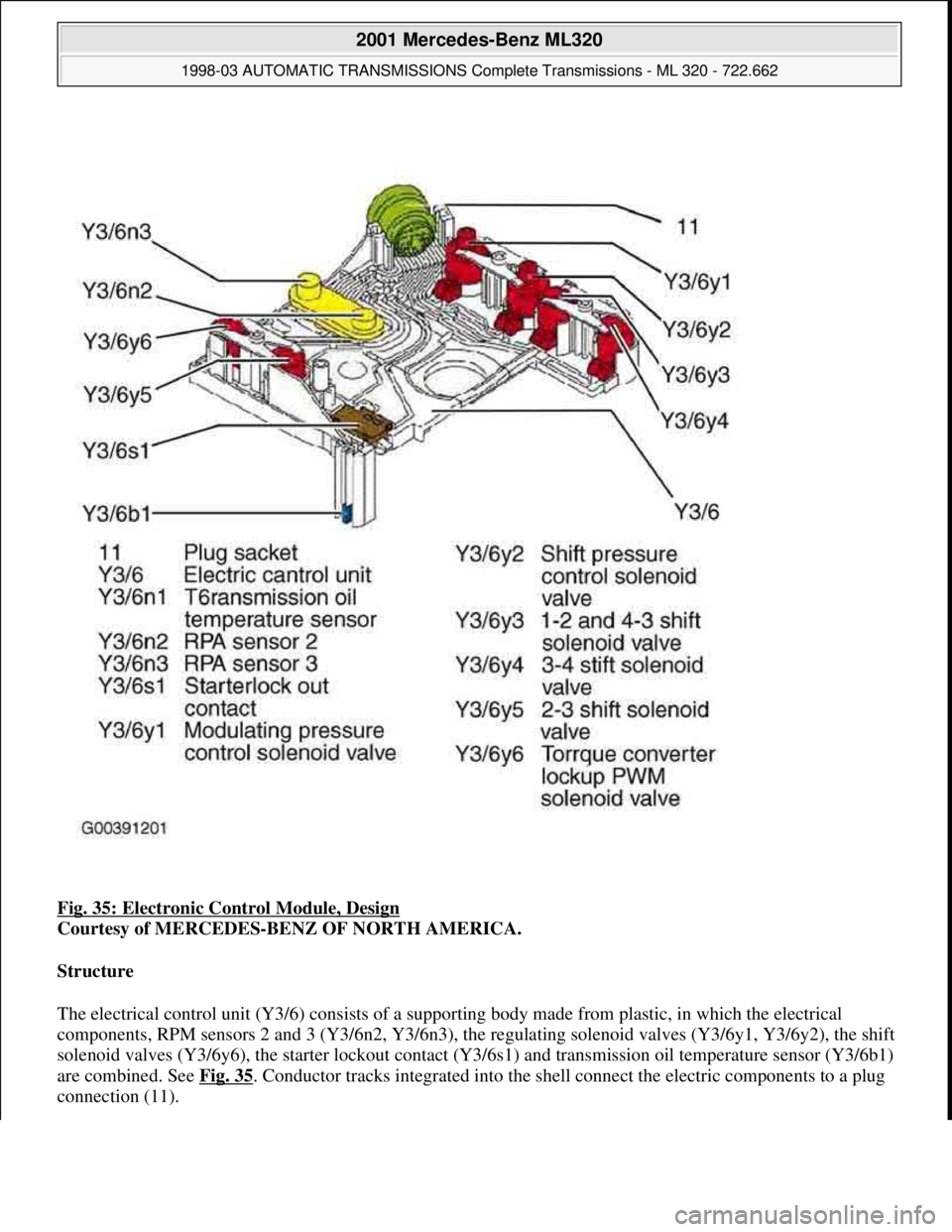
Fig. 35: Electronic Control Module, Design
Courtesy of MERCEDES-BENZ OF NORTH AMERICA.
Structure
The electrical control unit (Y3/6) consists of a supporting body made from plastic, in which the electrical
components, RPM sensors 2 and 3 (Y3/6n2, Y3/6n3), the regulating solenoid valves (Y3/6y1, Y3/6y2), the shift
solenoid valves (Y3/6y6), the starter lockout contact (Y3/6s1) and transmission oil temperature sensor (Y3/6b1)
are combined. See Fig. 35
. Conductor tracks integrated into the shell connect the electric components to a plug
connection (11).
2001 Mercedes-Benz ML320
1998-03 AUTOMATIC TRANSMISSIONS Complete Transmissions - ML 320 - 722.662
me
Saturday, October 02, 2010 3:15:26 PMPage 71 © 2006 Mitchell Repair Information Company, LLC.
Page 1243 of 4133
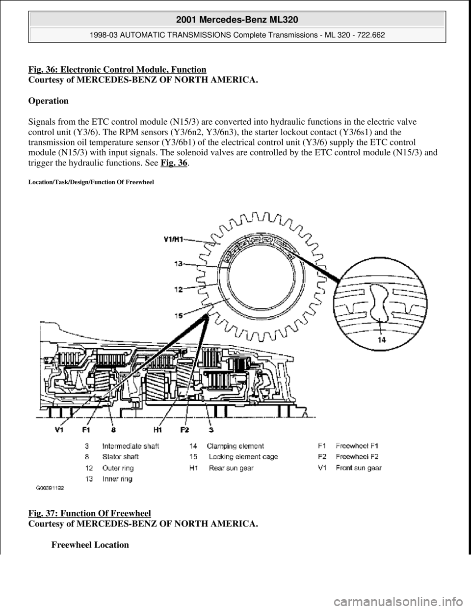
Fig. 36: Electronic Control Module, Function
Courtesy of MERCEDES-BENZ OF NORTH AMERICA.
Operation
Signals from the ETC control module (N15/3) are conve rted into hydraulic functions in the electric valve
control unit (Y3/6). The RPM sensors (Y3/6n2, Y3/6n3) , the starter lockout contact (Y3/6s1) and the
transmission oil temperature sensor (Y3/6b1) of the electrical cont rol unit (Y3/6) supply the ETC control
module (N15/3) with input signals. The solenoid valves are controlled by the ETC control module (N15/3) and
trigger the hydraulic functions. See Fig. 36
.
Location/Task/Design/Function Of Freewheel
Fig. 37: Function Of Freewheel
Courtesy of MERCEDES-BENZ OF NORTH AMERICA.
Freewheel Location
2001 Mercedes-Benz ML320
1998-03 AUTOMATIC TRANSMI SSIONS Complete Transmissions - ML 320 - 722.662
me
Saturday, October 02, 2010 3:15:26 PMPage 74 © 2006 Mitchell Repair Information Company, LLC.
Page 1247 of 4133
Transmission Housing Breather, Location
The inside of the transmission and the breather (72) are connected by a channel which is cast into the
torque converter casing. See Fig. 39
.
Transmission Housing Breather, Task
The transmission housing vent compensated the pressure in the transmission housing if temperature-
related volume changes in the transmission oil and air occur.
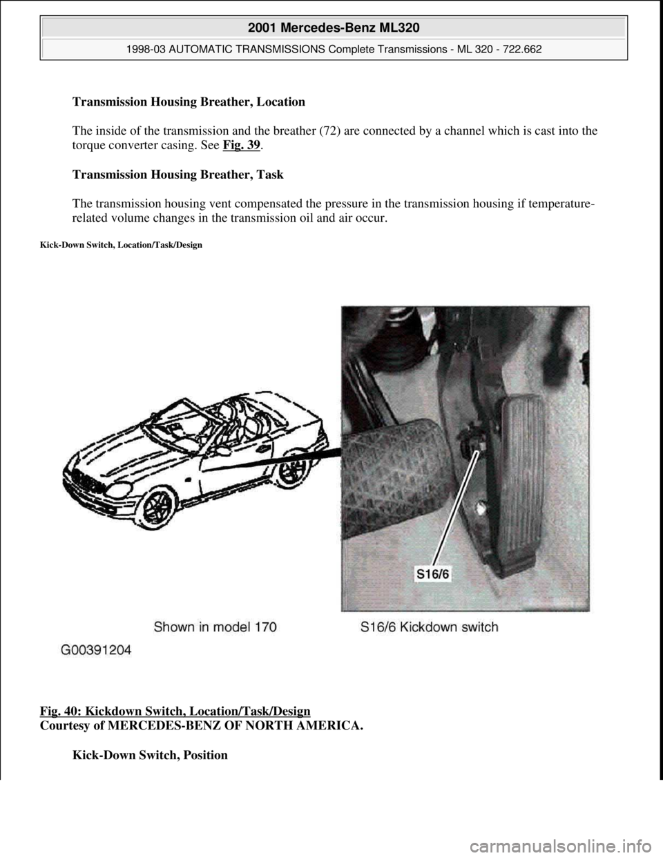
Kick-Down Switch, Location/Task/Design
Fig. 40: Kickdown Switch, Location/Task/Design
Courtesy of MERCEDES-BENZ OF NORTH AMERICA.
Kick-Down Switch, Position
2001 Mercedes-Benz ML320
1998-03 AUTOMATIC TRANSMISSIONS Complete Transmissions - ML 320 - 722.662
me
Saturday, October 02, 2010 3:15:26 PMPage 78 © 2006 Mitchell Repair Information Company, LLC.
Page 1333 of 4133
Task - The ETC control module (N15/3) determines the instantaneous operating condition of the vehicle and
controls all gearshift sequences taking into account the ease of shifting and the driving situation. This involves
receiving, converting and transmitting various digital and analog signals. See Fig. 96
.
It receives operating data in the form of input signals from:
Starter Lock-Out Contact (Y3/6S1)
RPM Sensor 2 (Y3/6N2)
RPM Sensor 3 (Y3/6n3)
Transmission Oil Temperature Sensor (Y3/6B1)
In addition there is a connection via the engine compartment bus to the:
Instrument Cluster (A1)
ME-SFI Control Module (N3/10) or CDI Control Module (N3/9)
The solenoid valves for the modulating and shift pressure and for the gear changes are actuated by the ETC
control module (N15/3).
The pressure required is calculated from all input signals, adjusted to the torque to be transferred. The following
information from other systems is then processed.
ME-SFI Control Module (N3/10) or CDI Control Module (N3/9):
Engine Torque
Engine Speed
Accelerator Pedal Position
Gear Shift
Engine Status
Electronic Selector Lever Module Control Module (N15/5):
Kickdown Switch (S16/6)
Selector Lever Position P/N
Traction System Control Module (N47):
Transmission Ratio
Speeds
Instrument Cluster (A1):
Selector Lever Position/Shift Range
2001 Mercedes-Benz ML320
1998-03 AUTOMATIC TRANSMISSIONS Complete Transmissions - ML 320 - 722.662
me
Saturday, October 02, 2010 3:15:27 PMPage 164 © 2006 Mitchell Repair Information Company, LLC.
Page 1335 of 4133
Courtesy of MERCEDES-BENZ OF NORTH AMERICA.
Task - The ETC control module (N15/3) determines the instantaneous operating condition for the vehicle and
controls all gearshift sequences taking into account the ease of shifting and the driving situation. See Fig. 97
.
This involves receiving , converting and transmitting various digital and analog signals.
Input signals:
Starter Lock-Out Contact (Y3/6S1)
RPM Sensor 2 (Y3/6N2)
RPM Sensor 3 (Y3/6N3)
Transmission Oil Temperature Sensor (Y3/6B1)
Kickdown Switch (S16/6)
Gear Recognition Switch (S16/10)
Output signals:
Reverse/parking lock valve
Input and output signals:
Datalink connector (X11/4)
In addition there is a connection via the engine compartment bus to the:
ME-SFI Control Module (N3/10) or CDI Control Module (N3/9)
Traction System Control Module (N47)
Transfer Case Control Module (N78)
The solenoid valves for the modulating and shift pressure and for the gear changes are actuated by the ETC
control module (N15/3). The pressure required is calculated from all input signals, adjusted to the torque to be
transferred.
The following information from other systems is then processed:
ME-SFI Control Module (N3/10) or CDI Control Module (N3/9)
(Y66/1)
Selector lever position P/N to the engine control module (ME-SFI) (N3/10) (only on detection of the
selector lever position "P" or "N" on the transmission range recognition switch (S16/10) and at the starter
interlock contact (Y3/6s1)).
Traction system control module (N47):
Wheel speeds
2001 Mercedes-Benz ML320
1998-03 AUTOMATIC TRANSMISSIONS Complete Transmissions - ML 320 - 722.662
me
Saturday, October 02, 2010 3:15:27 PMPage 166 © 2006 Mitchell Repair Information Company, LLC.
Page 1346 of 4133
Courtesy of MECHANICS MONTHLY MAGAZINE
Temperature Sensor, Location
The transmission oil temperature sensor (Y3/6bl) is located in the electrical control unit (Y3/6) and is
permanently connected to the conductor tracks. See Fig. 102
.
Temperature Sensor, Task
To measure the temperature of the transmission oil and pass the temperature to the ETC control unit
(N15/3) as an input signal.
Temperature Sensor, Design
Temperature-dependent resistor (PTC).
Temperature Sensor, Function
See TEMPERATURE SENSOR, FUNCTION
.
Temperature Sensor, Function
2001 Mercedes-Benz ML320
1998-03 AUTOMATIC TRANSMISSIONS Complete Transmissions - ML 320 - 722.662
me
Saturday, October 02, 2010 3:15:28 PMPage 177 © 2006 Mitchell Repair Information Company, LLC.
Page 1347 of 4133
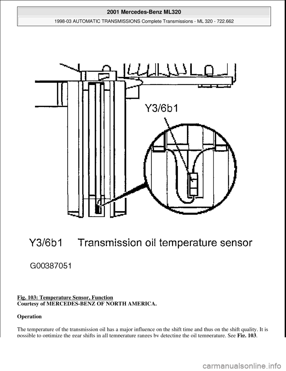
Fig. 103: Temperature Sensor, Function
Courtesy of MERCEDES-BENZ OF NORTH AMERICA.
Operation
The temperature of the transmission oil has a major influence on the shift time and thus on the shift quality. It is
possible to optimize the gear shifts in all temperature ranges by detecting the oil temperature. See Fig. 103.
2001 Mercedes-Benz ML320
1998-03 AUTOMATIC TRANSMISSIONS Complete Transmissions - ML 320 - 722.662
me
Saturday, October 02, 2010 3:15:28 PMPage 178 © 2006 Mitchell Repair Information Company, LLC.