wiring diagram MERCEDES-BENZ ML320 1997 Complete Owner's Guide
[x] Cancel search | Manufacturer: MERCEDES-BENZ, Model Year: 1997, Model line: ML320, Model: MERCEDES-BENZ ML320 1997Pages: 4133, PDF Size: 88.89 MB
Page 1688 of 4133
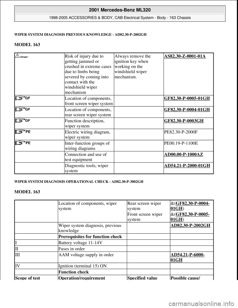
WIPER SYSTEM DIAGNOSIS PREVIOUS KNOWLEDGE - AD82.30-P-2002GH
MODEL 163
WIPER SYSTEM DIAGNOSIS OPERATIONAL CHECK - AD82.30-P-3002GH
MODEL 163
Risk of injury due to
getting jammed or
crushed in extreme cases
due to limbs being
severed by coming into
contact with the
windshield wiper
mechanismAlways remove the
ignition key when
working on the
windshield wiper
mechanism.AS82.30-Z-0001-01A
Location of components,
front screen wiper system GF82.30-P-0005-01GH
Location of components,
rear screen wiper system GF82.30-P-0004-01GH
Function description,
wiper system GF82.30-P-0003GH
Electric wiring diagram,
wiper system PE82.30-P-2000F
Inter-function groups of
wiring diagrams PE00.19-P-1100E
Connection and use of
test equipment AD00.00-P-1000AZ
Diagnostic tools, wiper
system AD54.21-P-2000-01GH
Location of components, wiper
systemRear screen wiper
system&(GF82.30-P-0004-
01GH)
Front screen wiper
system&(GF82.30-P-0005-
01GH)
Wiper system diagnosis, previous
knowledge AD82.30-P-2002GH
Prerequisites for function check
IBattery voltage 11-14V
IIFuses in order
IIIAAM voltage supply in order AD54.21-P-6000-
01GH
IVIgnition (terminal 15) ON
Function check
Scope of test Operation/requirement Specified value Possible cause/
2001 Mercedes-Benz ML320
1998-2005 ACCESSORIES & BODY, CAB Electrical System - Body - 163 Chassis
me
Saturday, October 02, 2010 3:30:07 PMPage 193 © 2006 Mitchell Repair Information Company, LLC.
Page 1699 of 4133
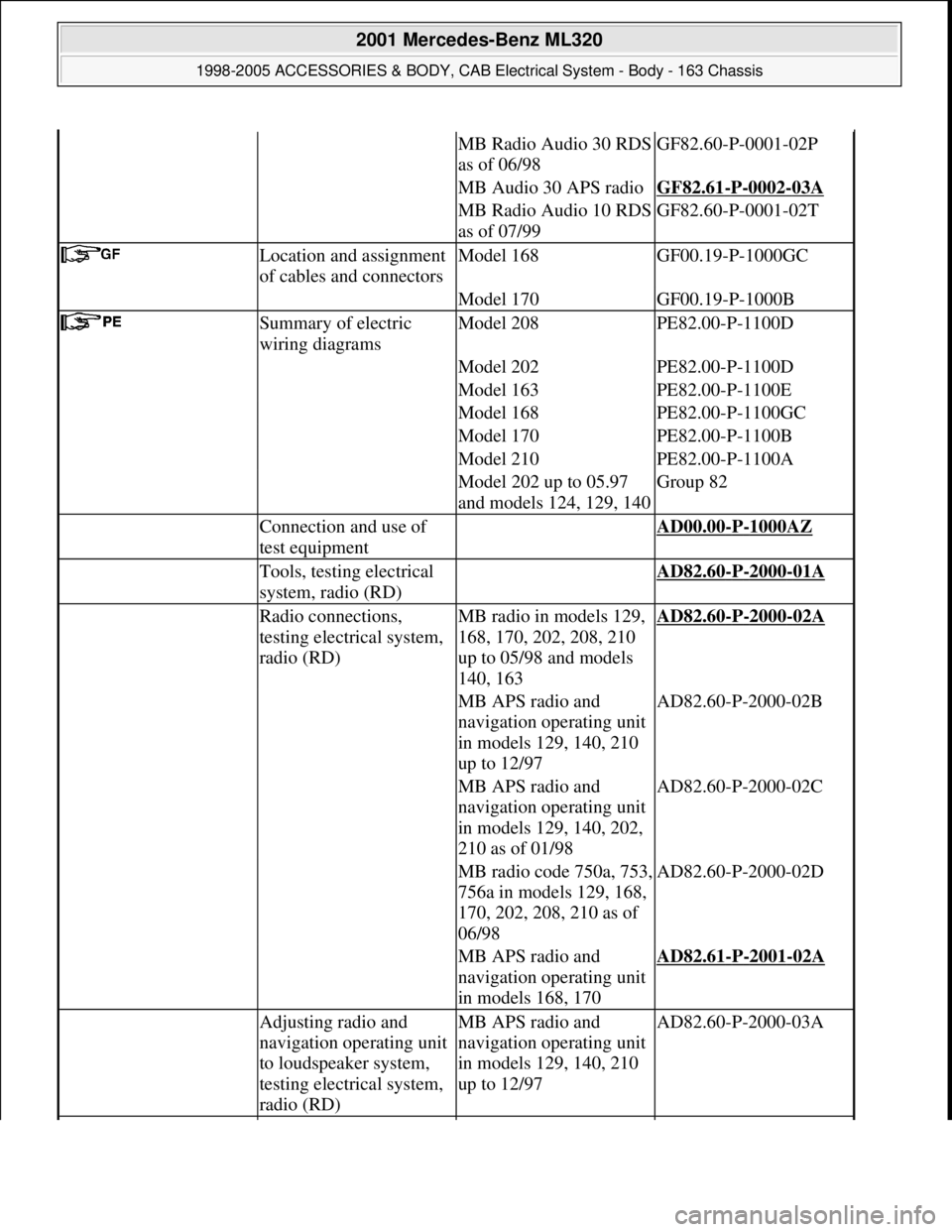
MB Radio Audio 30 RDS
as of 06/98GF82.60-P-0001-02P
MB Audio 30 APS radioGF82.61-P-0002-03A
MB Radio Audio 10 RDS
as of 07/99GF82.60-P-0001-02T
Location and assignment
of cables and connectorsModel 168GF00.19-P-1000GC
Model 170GF00.19-P-1000B
Summary of electric
wiring diagramsModel 208PE82.00-P-1100D
Model 202PE82.00-P-1100D
Model 163PE82.00-P-1100E
Model 168PE82.00-P-1100GC
Model 170PE82.00-P-1100B
Model 210PE82.00-P-1100A
Model 202 up to 05.97
and models 124, 129, 140Group 82
Connection and use of
test equipment AD00.00-P-1000AZ
Tools, testing electrical
system, radio (RD) AD82.60-P-2000-01A
Radio connections,
testing electrical system,
radio (RD)MB radio in models 129,
168, 170, 202, 208, 210
up to 05/98 and models
140, 163AD82.60-P-2000-02A
MB APS radio and
navigation operating unit
in models 129, 140, 210
up to 12/97AD82.60-P-2000-02B
MB APS radio and
navigation operating unit
in models 129, 140, 202,
210 as of 01/98AD82.60-P-2000-02C
MB radio code 750a, 753,
756a in models 129, 168,
170, 202, 208, 210 as of
06/98AD82.60-P-2000-02D
MB APS radio and
navigation operating unit
in models 168, 170AD82.61-P-2001-02A
Adjusting radio and
navigation operating unit
to loudspeaker system,
testing electrical system,
radio (RD)MB APS radio and
navigation operating unit
in models 129, 140, 210
up to 12/97AD82.60-P-2000-03A
2001 Mercedes-Benz ML320
1998-2005 ACCESSORIES & BODY, CAB Electrical System - Body - 163 Chassis
me
Saturday, October 02, 2010 3:30:07 PMPage 204 © 2006 Mitchell Repair Information Company, LLC.
Page 1712 of 4133
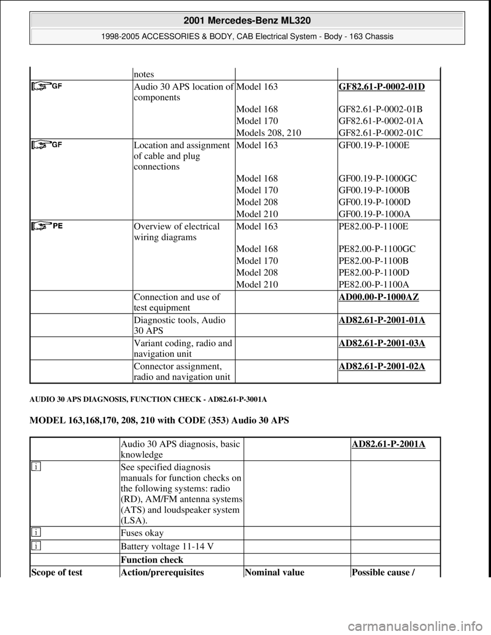
AUDIO 30 APS DIAGNOSIS, FUNCTION CHECK - AD82.61-P-3001A
MODEL 163,168,170, 208, 210 with CODE (353) Audio 30 APS
notes
Audio 30 APS location of
componentsModel 163GF82.61-P-0002-01D
Model 168GF82.61-P-0002-01B
Model 170GF82.61-P-0002-01A
Models 208, 210GF82.61-P-0002-01C
Location and assignment
of cable and plug
connectionsModel 163GF00.19-P-1000E
Model 168GF00.19-P-1000GC
Model 170GF00.19-P-1000B
Model 208GF00.19-P-1000D
Model 210GF00.19-P-1000A
Overview of electrical
wiring diagramsModel 163PE82.00-P-1100E
Model 168PE82.00-P-1100GC
Model 170PE82.00-P-1100B
Model 208PE82.00-P-1100D
Model 210PE82.00-P-1100A
Connection and use of
test equipment AD00.00-P-1000AZ
Diagnostic tools, Audio
30 APS AD82.61-P-2001-01A
Variant coding, radio and
navigation unit AD82.61-P-2001-03A
Connector assignment,
radio and navigation unit AD82.61-P-2001-02A
Audio 30 APS diagnosis, basic
knowledge AD82.61-P-2001A
See specified diagnosis
manuals for function checks on
the following systems: radio
(RD), AM/FM antenna systems
(ATS) and loudspeaker system
(LSA).
Fuses okay
Battery voltage 11-14 V
Function check
Scope of test Action/prerequisites Nominal value Possible cause /
2001 Mercedes-Benz ML320
1998-2005 ACCESSORIES & BODY, CAB Electrical System - Body - 163 Chassis
me
Saturday, October 02, 2010 3:30:08 PMPage 217 © 2006 Mitchell Repair Information Company, LLC.
Page 1726 of 4133
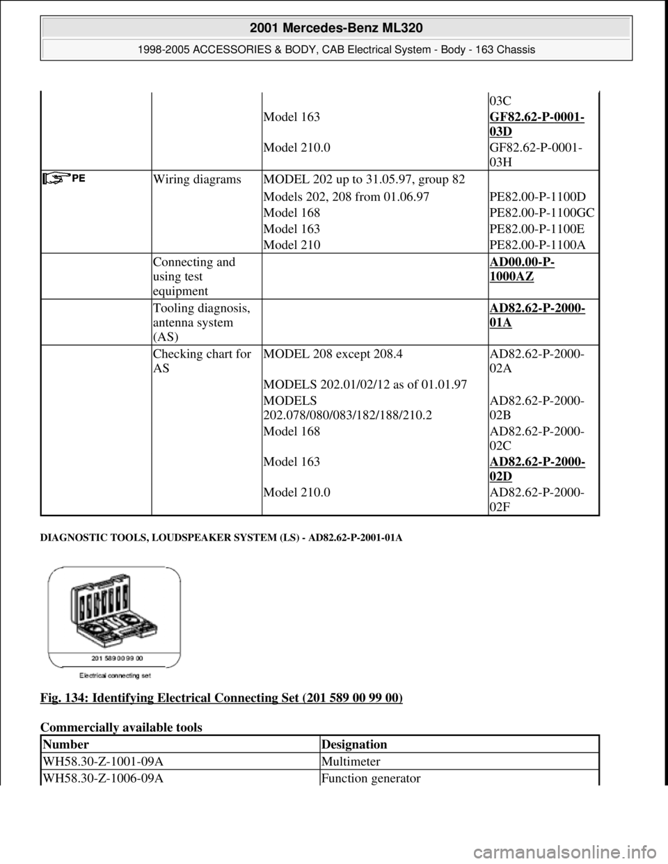
DIAGNOSTIC TOOLS, LOUDSPEAKER SYSTEM (LS) - AD82.62-P-2001-01A
Fig. 134: Identifying Electrical Connecting Set (201 589 00 99 00)
Commercially available tools
03C
Model 163GF82.62-P-0001-
03D
Model 210.0GF82.62-P-0001-
03H
Wiring diagramsMODEL 202 up to 31.05.97, group 82
Models 202, 208 from 01.06.97PE82.00-P-1100D
Model 168PE82.00-P-1100GC
Model 163PE82.00-P-1100E
Model 210PE82.00-P-1100A
Connecting and
using test
equipment AD00.00-P-
1000AZ
Tooling diagnosis,
antenna system
(AS) AD82.62-P-2000-
01A
Checking chart for
ASMODEL 208 except 208.4AD82.62-P-2000-
02A
MODELS 202.01/02/12 as of 01.01.97
MODELS
202.078/080/083/182/188/210.2AD82.62-P-2000-
02B
Model 168AD82.62-P-2000-
02C
Model 163AD82.62-P-2000-
02D
Model 210.0AD82.62-P-2000-
02F
NumberDesignation
WH58.30-Z-1001-09AMultimeter
WH58.30-Z-1006-09AFunction generator
2001 Mercedes-Benz ML320
1998-2005 ACCESSORIES & BODY, CAB Electrical System - Body - 163 Chassis
me
Saturday, October 02, 2010 3:30:08 PMPage 231 © 2006 Mitchell Repair Information Company, LLC.
Page 1727 of 4133
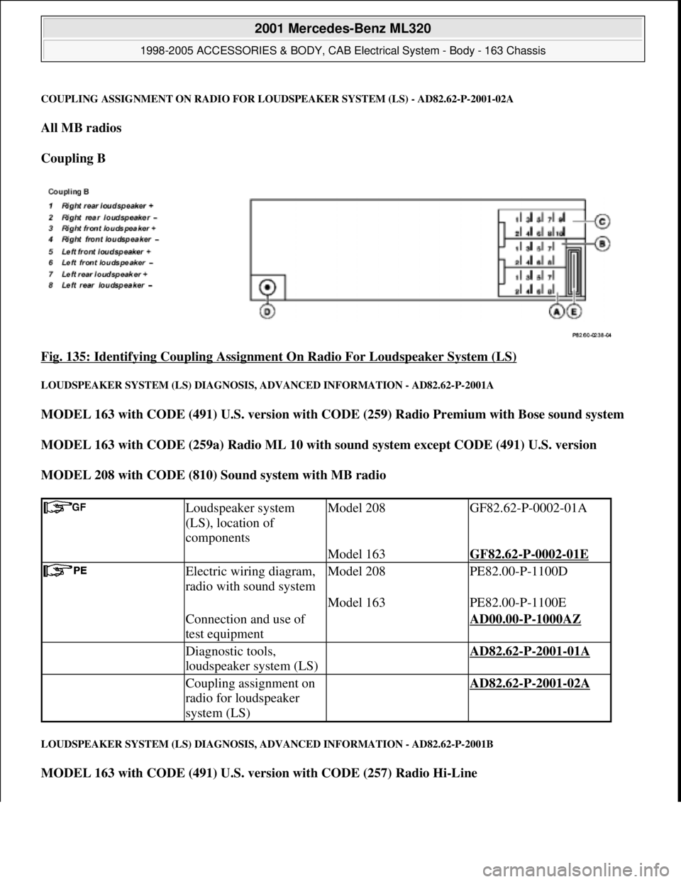
COUPLING ASSIGNMENT ON RADIO FOR LOUDSPEAKER SYSTEM (LS) - AD82.62-P-2001-02A
All MB radios
Coupling B
Fig. 135: Identifying Coupling Assignment On Radio For Loudspeaker System (LS)
LOUDSPEAKER SYSTEM (LS) DIAGNOSIS, ADVANCED INFORMATION - AD82.62-P-2001A
MODEL 163 with CODE (491) U.S. version with CODE (259) Radio Premium with Bose sound system
MODEL 163 with CODE (259a) Radio ML 10 with sound system except CODE (491) U.S. version
MODEL 208 with CODE (810) Sound system with MB radio
LOUDSPEAKER SYSTEM (LS) DIAGNOSIS, ADVANCED INFORMATION - AD82.62-P-2001B
MODEL 163 with CODE (491) U.S. version with CODE (257) Radio Hi-Line
Loudspeaker system
(LS), location of
componentsModel 208GF82.62-P-0002-01A
Model 163GF82.62-P-0002-01E
Electric wiring diagram,
radio with sound systemModel 208PE82.00-P-1100D
Model 163PE82.00-P-1100E
Connection and use of
test equipment AD00.00-P-1000AZ
Diagnostic tools,
loudspeaker system (LS) AD82.62-P-2001-01A
Coupling assignment on
radio for loudspeaker
system (LS) AD82.62-P-2001-02A
2001 Mercedes-Benz ML320
1998-2005 ACCESSORIES & BODY, CAB Electrical System - Body - 163 Chassis
me
Saturday, October 02, 2010 3:30:08 PMPage 232 © 2006 Mitchell Repair Information Company, LLC.
Page 1728 of 4133
MODEL 163 with CODE (257a) Radio ML 5 except CODE (491) U.S. version
MODEL 168, 208 with MB radio
AM AND FM WAVE BANDS, DIAGNOSIS, FUNCTION CHECK, AS - AD82.62-P-3000-01A
Function check
Set radio as follows: Set station with poor reception (music) and fader, bass, treble and balance in
position 0 (shown in display).
Check AM and FM wave bands by driving in a circle in a yard (open-air grounds) to establish the
reception quality.
Possibly repeat the test with an identical vehicle for comparison.
It is absolutely essential to perform the comparison measurement at the same location and with the same
station setting .
Repeat the test after replacing a component.
ANTENNA SYSTEM (AS) DIAGNOSIS, FUNCTION CHECK - AD82.62-P-3000A
MODELS 163, 168, 202.078 /080 /083 /182 /188, 208 (except, 208.4), 202.01 /02/12 as of 1.1.97, 210.0 /2
Loudspeaker system
(LS), location of
componentsModel 208GF82.62-P-0002-01B
Model 168 ModelGF82.62-P-0002-01C
163GF82.62-P-0002-01D
Electric wiring diagramsModel 208PE82.00-P-1100D
Model 168PE82.00-P-1100GC
Model 163PE82.00-P-1100E
Connection and use of
test equipment AD00.00-P-1000AZ
Diagnostic tools,
loudspeaker system (LS) AD82.62-P-2001-01A
Coupling assignment on
radio for loudspeaker
system (LS) AD82.62-P-2001-02A
Antenna system (AS)
diagnosis, previous
knowledge AD82.62-P-2000A
Operational check
Test of Operation /
Requirement Specified value possible cause/ Remedy
2001 Mercedes-Benz ML320
1998-2005 ACCESSORIES & BODY, CAB Electrical System - Body - 163 Chassis
me
Saturday, October 02, 2010 3:30:08 PMPage 233 © 2006 Mitchell Repair Information Company, LLC.
Page 1741 of 4133
CD PLAYER WITH CHANGER (CDC) DIAGNOSIS, FUNCTION CHECK - AD82.64-P-3000A
MODEL 124,163,168, 202, 208, 210 with CODE (819) 6-disk CD changer in trunk
MODEL 129 as of 1.6.98 with CODE (819) 6-disk CD changer in trunk
MODEL 638 with CODE (EP5) CD changer
location
Wiring diagramsModels 202, 208 as of
06/97PE82.00-P-1100D
Model 210PE82.00-P-1100A
Model 163PE82.00-P-1100E
Model 168PE82.00-P-1100GC
Models 124, 129 and
Model 202 up to 05/97,
Group 82
Connecting and using test
equipment AD00.00-P-1000AZ
Tools for checking the
electrical system, CD
player with changer AD82.64-P-2000-01A
CD player with changer,
connectionsModels 202, 208, 210 up
to 05/98 and Models 124,
168AD82.64-P-2000-02A
Model 163AD82.64-P-2000-02B
Models 129, 202, 208,
210 as of 06/98AD82.64-P-2000-02C
CD changer (CDC) diagnosis,
previous knowledgeModels 124, 129,
163, 168, 202, 208,
210AD82.64-P-2000A
Model 638: DMNL
Vito/V-class, CDCAD82.64-S-2000A
Battery voltage 11 - 14 V
Fuses okay
Radio in order
CD magazine of changer fitted
with satisfactory CDs free
from protective film
Function check
Scope of test Operation/Requirement Specified value Possible cause/
Remedy
1 Radio: ON CD operation must be AD82.64-P-5000A
2001 Mercedes-Benz ML320
1998-2005 ACCESSORIES & BODY, CAB Electrical System - Body - 163 Chassis
me
Saturday, October 02, 2010 3:30:08 PMPage 246 © 2006 Mitchell Repair Information Company, LLC.
Page 1833 of 4133
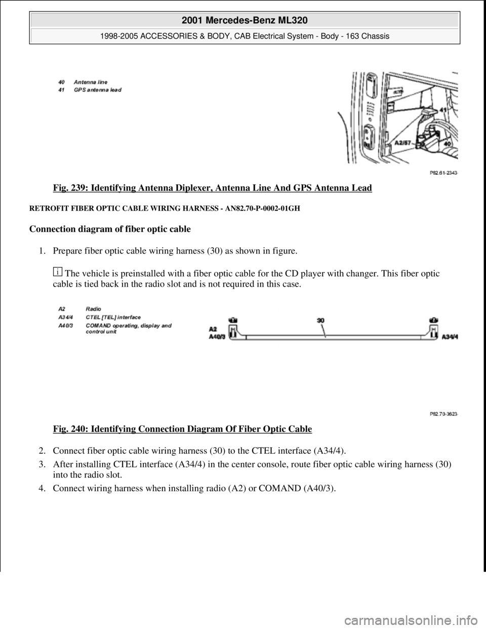
Fig. 239: Identifying Antenna Diplexer, Antenna Line And GPS Antenna Lead
RETROFIT FIBER OPTIC CABLE WIRING HARNESS - AN82.70-P-0002-01GH
Connection diagram of fiber optic cable
1. Prepare fiber optic cable wiring harness (30) as shown in figure.
The vehicle is preinstalled with a fiber optic cable for the CD player with changer. This fiber optic
cable is tied back in the radio slot and is not required in this case.
Fig. 240: Identifying Connection Diagram Of Fiber Optic Cable
2. Connect fiber optic cable wiring harness (30) to the CTEL interface (A34/4).
3. After installing CTEL interface (A34/4) in the center console, route fiber optic cable wiring harness (30)
into the radio slot.
4. Connect wiring harness when installing radio (A2) or COMAND (A40/3).
2001 Mercedes-Benz ML320
1998-2005 ACCESSORIES & BODY, CAB Electrical System - Body - 163 Chassis
me
Saturday, October 02, 2010 3:30:11 PMPage 338 © 2006 Mitchell Repair Information Company, LLC.
Page 1836 of 4133
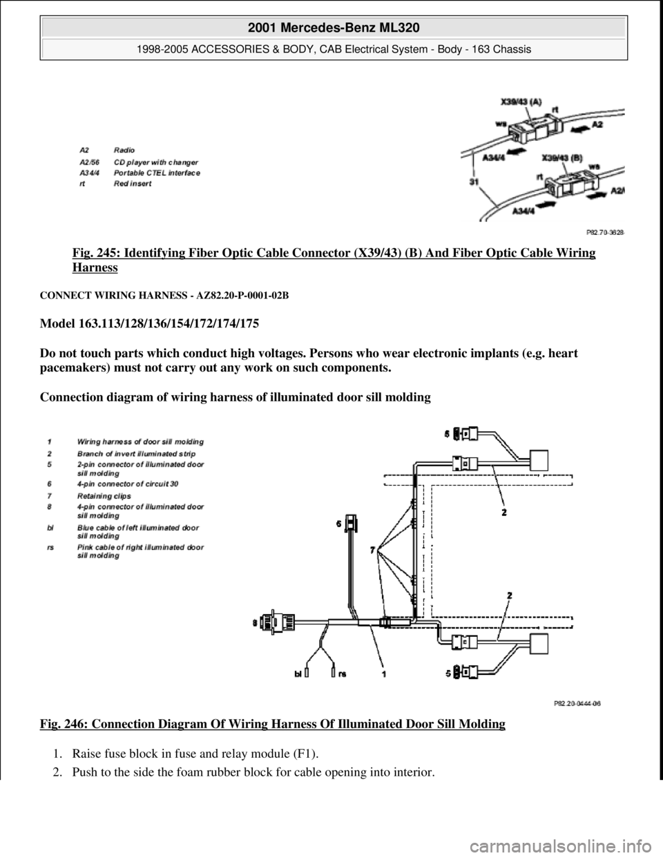
Fig. 245: Identifying Fiber Optic Cable Connector (X39/43) (B) And Fiber Optic Cable Wiring
Harness
CONNECT WIRING HARNESS - AZ82.20-P-0001-02B
Model 163.113/128/136/154/172/174/175
Do not touch parts which conduct high voltages. Persons who wear electronic implants (e.g. heart
pacemakers) must not carry out any work on such components.
Connection diagram of wiring harness of illuminated door sill molding
Fig. 246: Connection Diagram Of Wiring Harness Of Illuminated Door Sill Molding
1. Raise fuse block in fuse and relay module (F1).
2. Push to the side the foam rubber block for cable openin
g into interior.
2001 Mercedes-Benz ML320
1998-2005 ACCESSORIES & BODY, CAB Electrical System - Body - 163 Chassis
me
Saturday, October 02, 2010 3:30:11 PMPage 341 © 2006 Mitchell Repair Information Company, LLC.
Page 2043 of 4133
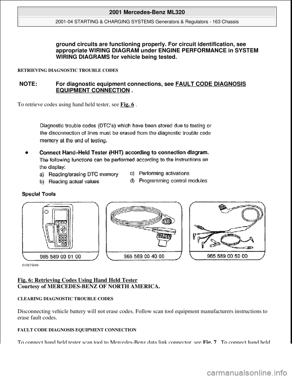
RETRIEVING DIAGNOSTIC TROUBLE CODES
To retrieve codes using hand held tester, see Fig. 6 .
Fig. 6: Retrieving Codes Using Hand Held Tester
Courtesy of MERCEDES-BENZ OF NORTH AMERICA.
CLEARING DIAGNOSTIC TROUBLE CODES
Disconnecting vehicle battery will not erase codes. Follow scan tool equipment manufacturers instructions to
erase fault codes.
FAULT CODE DIAGNOSIS EQUIPMENT CONNECTION
To connect hand held tester scan tool to Mercedes-Benz data link connector, see Fig. 7 . To connect hand held
ground circuits are functioning properl
y. For circuit identification, see
appropriate WIRING DIAGRAM unde r ENGINE PERFORMANCE in SYSTEM
WIRING DIAGRAMS for vehicle being tested.
NOTE: For diagnostic equipment conn ections, see FAULT CODE DIAGNOSIS
EQUIPMENT CONNECTION .
2001 Mercedes-Benz ML320
2001-04 STARTING & CHARGING SYSTEMS Gene rators & Regulators - 163 Chassis
me
Saturday, October 02, 2010 3:20:32 PMPage 9 © 2006 Mitchell Repair Information Company, LLC.