wiring diagram MERCEDES-BENZ ML320 1997 Complete Service Manual
[x] Cancel search | Manufacturer: MERCEDES-BENZ, Model Year: 1997, Model line: ML320, Model: MERCEDES-BENZ ML320 1997Pages: 4133, PDF Size: 88.89 MB
Page 2060 of 4133
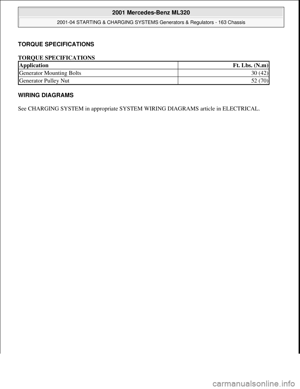
TORQUE SPECIFICATIONS
TORQUE SPECIFICATIONS
WIRING DIAGRAMS
See CHARGING SYSTEM in appropriate SYSTEM WIRING DIAGRAMS article in ELECTRICAL.
ApplicationFt. Lbs. (N.m)
Generator Mounting Bolts30 (42)
Generator Pulley Nut52 (70)
2001 Mercedes-Benz ML320
2001-04 STARTING & CHARGING SYSTEMS Generators & Regulators - 163 Chassis
me
Saturday, October 02, 2010 3:20:32 PMPage 26 © 2006 Mitchell Repair Information Company, LLC.
Page 2672 of 4133
Plugs and couplings. with yellow, orange or red housing colors are reserved for safety and restraint systems
(SRS) and roll bars.
Observe the following when repairing couplings for squibs (SRS systems):
The repair area must be between 100 mm and 1000 mm behind the squib. Cables which have already been
repaired are provided with a yellow marking. This is to be applied retroactively to repair lines without color
marking.
Carry out the first repair as close to the plug as possible. In the case of subsequent repairs the old soldered
connectors should be removed and the new ones should be attached behind them, the wiring harness should be
replaced if necessary.
Before cutting through the lines it is absolutely essential to assign the lines to the corresponding pins in
accordance with the wiring diagram. Do not mix up the pin assignment.
The line colors of the repair kit may deviate from the original fitting
Screened lines and light plastic-sheathed cable must never be repaired
In general the following applies to cable repair:
If more than ten lines per branch-off line are damaged, the wiring harness module must be replaced.
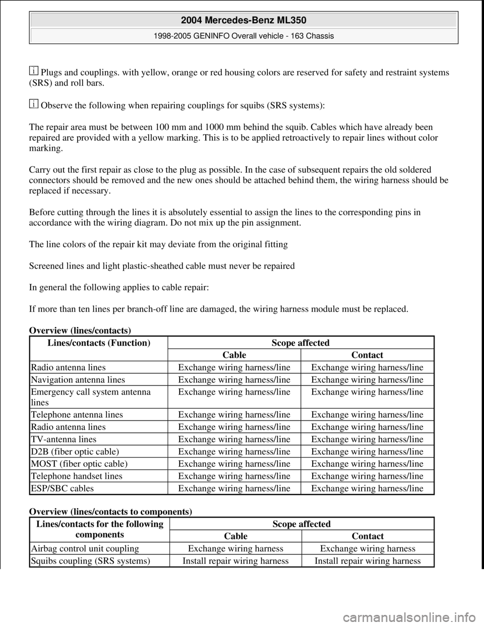
Overview (lines/contacts)
Overview (lines/contacts to components)
Lines/contacts (Function)Scope affected
CableContact
Radio antenna linesExchange wiring harness/lineExchange wiring harness/line
Navigation antenna linesExchange wiring harness/lineExchange wiring harness/line
Emergency call system antenna
linesExchange wiring harness/lineExchange wiring harness/line
Telephone antenna linesExchange wiring harness/lineExchange wiring harness/line
Radio antenna linesExchange wiring harness/lineExchange wiring harness/line
TV-antenna linesExchange wiring harness/lineExchange wiring harness/line
D2B (fiber optic cable)Exchange wiring harness/lineExchange wiring harness/line
MOST (fiber optic cable)Exchange wiring harness/lineExchange wiring harness/line
Telephone handset linesExchange wiring harness/lineExchange wiring harness/line
ESP/SBC cablesExchange wiring harness/lineExchange wiring harness/line
Lines/contacts for the following
componentsScope affected
CableContact
Airbag control unit couplingExchange wiring harnessExchange wiring harness
Squibs coupling (SRS systems)Install repair wiring harnessInstall repair wiring harness
2004 Mercedes-Benz ML350
1998-2005 GENINFO Overall vehicle - 163 Chassis
me
Saturday, October 02, 2010 3:47:44 PMPage 27 © 2006 Mitchell Repair Information Company, LLC.
Page 3213 of 4133
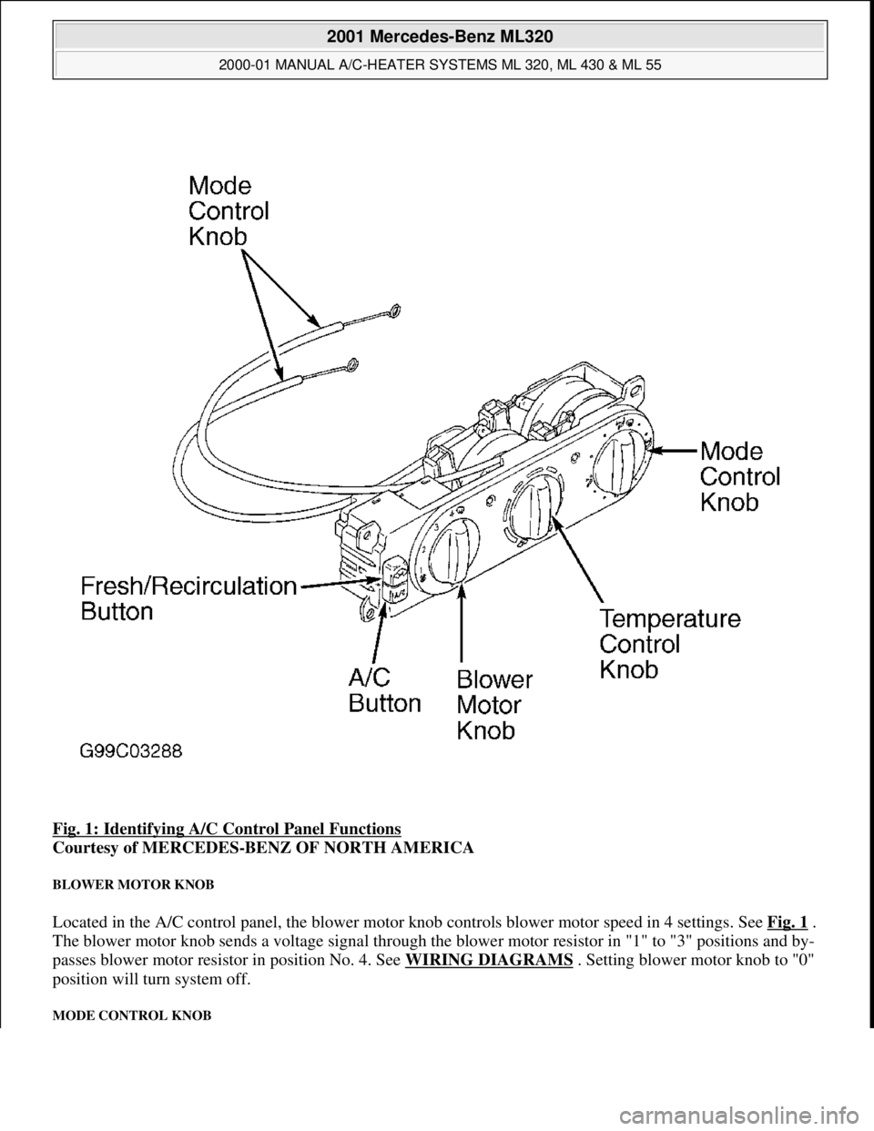
Fig. 1: Identifying A/C Control Panel Functions
Courtesy of MERCEDES-BENZ OF NORTH AMERICA
BLOWER MOTOR KNOB
Located in the A/C control panel, the blower motor knob controls blower motor speed in 4 settings. See Fig. 1 .
The blower motor knob sends a voltage signal through the blower motor resistor in "1" to "3" positions and by-
passes blower motor resistor in position No. 4. See WIRING DIAGRAMS . Setting blower motor knob to "0"
position will turn system off.
MODE CONTROL KNOB
2001 Mercedes-Benz ML320
2000-01 MANUAL A/C-HEATER SYSTEMS ML 320, ML 430 & ML 55
me
Saturday, October 02, 2010 3:25:10 PMPage 2 © 2006 Mitchell Repair Information Company, LLC.
Page 3220 of 4133
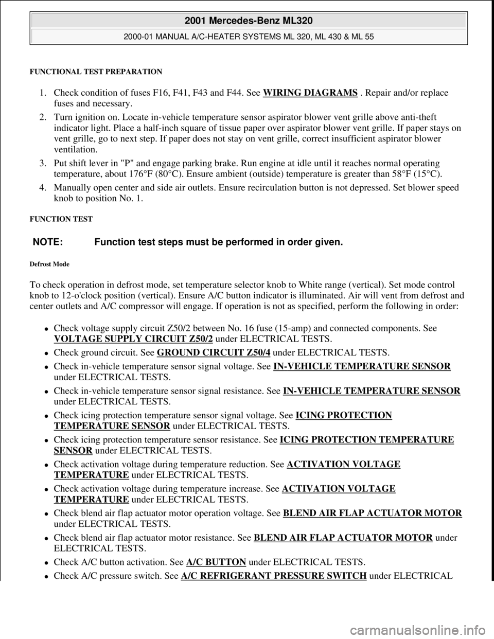
FUNCTIONAL TEST PREPARATION
1. Check condition of fuses F16, F41, F43 and F44. See WIRING DIAGRAMS . Repair and/or replace
fuses and necessary.
2. Turn ignition on. Locate in-vehicle temperature sensor aspirator blower vent grille above anti-theft
indicator light. Place a half-inch square of tissue paper over aspirator blower vent grille. If paper stays on
vent grille, go to next step. If paper does not stay on vent grille, correct insufficient aspirator blower
ventilation.
3. Put shift lever in "P" and engage parking brake. Run engine at idle until it reaches normal operating
temperature, about 176°F (80°C). Ensure ambient (outside) temperature is greater than 58°F (15°C).
4. Manually open center and side air outlets. Ensure recirculation button is not depressed. Set blower speed
knob to position No. 1.
FUNCTION TEST
Defrost Mode
To check operation in defrost mode, set temperature selector knob to White range (vertical). Set mode control
knob to 12-o'clock position (vertical). Ensure A/C button indicator is illuminated. Air will vent from defrost and
center outlets and A/C compressor will engage. If operation is not as specified, perform the following in order:
Check voltage supply circuit Z50/2 between No. 16 fuse (15-amp) and connected components. See
VOLTAGE SUPPLY CIRCUIT Z50/2
under ELECTRICAL TESTS.
Check ground circuit. See GROUND CIRCUIT Z50/4 under ELECTRICAL TESTS.
Check in-vehicle temperature sensor signal voltage. See IN-VEHICLE TEMPERATURE SENSOR
under ELECTRICAL TESTS.
Check in-vehicle temperature sensor signal resistance. See IN-VEHICLE TEMPERATURE SENSOR
under ELECTRICAL TESTS.
Check icing protection temperature sensor signal voltage. See ICING PROTECTION
TEMPERATURE SENSOR under ELECTRICAL TESTS.
Check icing protection temperature sensor resistance. See ICING PROTECTION TEMPERATURE
SENSOR under ELECTRICAL TESTS.
Check activation voltage during temperature reduction. See ACTIVATION VOLTAGE
TEMPERATURE under ELECTRICAL TESTS.
Check activation voltage during temperature increase. See ACTIVATION VOLTAGE
TEMPERATURE under ELECTRICAL TESTS.
Check blend air flap actuator motor operation voltage. See BLEND AIR FLAP ACTUATOR MOTOR
under ELECTRICAL TESTS.
Check blend air flap actuator motor resistance. See BLEND AIR FLAP ACTUATOR MOTOR under
ELECTRICAL TESTS.
Check A/C button activation. See A/C BUTTON under ELECTRICAL TESTS.
Check A/C pressure switch. See A/C REFRIGERANT PRESSURE SWITCH under ELECTRICAL NOTE: Function test steps must be performed in order given.
2001 Mercedes-Benz ML320
2000-01 MANUAL A/C-HEATER SYSTEMS ML 320, ML 430 & ML 55
me
Saturday, October 02, 2010 3:25:10 PMPage 9 © 2006 Mitchell Repair Information Company, LLC.
Page 3221 of 4133
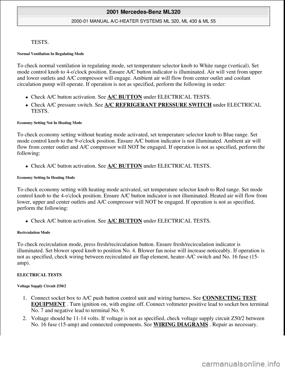
TESTS.
Normal Ventilation In Regulating Mode
To check normal ventilation in regulating mode, set temperature selector knob to White range (vertical). Set
mode control knob to 4-o'clock position. Ensure A/C button indicator is illuminated. Air will vent from upper
and lower outlets and A/C compressor will engage. Ambient air will flow from center outlet and coolant
circulation pump will operate. If operation is not as specified, perform the following in order:
Check A/C button activation. See A/C BUTTON under ELECTRICAL TESTS.
Check A/C pressure switch. See A/C REFRIGERANT PRESSURE SWITCH under ELECTRICAL
TESTS.
Economy Setting Not In Heating Mode
To check economy setting without heating mode activated, set temperature selector knob to Blue range. Set
mode control knob to the 9-o'clock position. Ensure A/C button indicator is not illuminated. Ambient air will
flow from center outlet and A/C compressor will NOT be engaged. If operation is not as specified, perform the
following:
Check A/C button activation. See A/C BUTTON under ELECTRICAL TESTS.
Economy Setting In Heating Mode
To check economy setting with heating mode activated, set temperature selector knob to Red range. Set mode
control knob to the 4-o'clock position. Ensure A/C button indicator is not illuminated. Heated air will flow from
lower, upper and center outlets and A/C compressor will NOT be engaged. If operation is not as specified,
perform the following:
Check A/C button activation. See A/C BUTTON under ELECTRICAL TESTS.
Recirculation Mode
To check recirculation mode, press fresh/recirculation button. Ensure fresh/recirculation indicator is
illuminated. Set blower speed knob to position No. 4. Blower fan noise will increase noticeably. If operation is
not as specified, check wiring between recirculated air flap element, heater-A/C switch and No. 16 fuse (15-
amp).
ELECTRICAL TESTS
Voltage Supply Circuit Z50/2
1. Connect socket box to A/C push button control unit and wiring harness. See CONNECTING TEST
EQUIPMENT . Turn ignition on, with engine off. Connect voltmeter positive lead to socket box terminal
No. 7 and negative lead to terminal No. 9.
2. Voltage should be 11-14 volts. If voltage is not as specified, check voltage supply circuit Z50/2 between
No. 16 fuse (15-amp) and connected components. See WIRING DIAGRAMS
. Repair as necessary.
2001 Mercedes-Benz ML320
2000-01 MANUAL A/C-HEATER SYSTEMS ML 320, ML 430 & ML 55
me
Saturday, October 02, 2010 3:25:10 PMPage 10 © 2006 Mitchell Repair Information Company, LLC.
Page 3222 of 4133
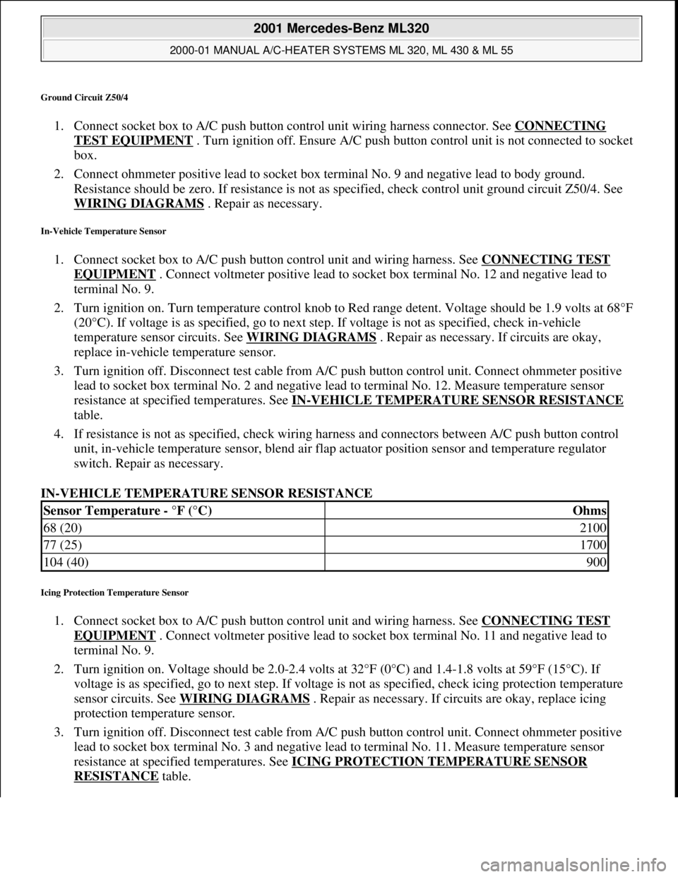
Ground Circuit Z50/4
1. Connect socket box to A/C push button control unit wiring harness connector. See CONNECTING
TEST EQUIPMENT . Turn ignition off. Ensure A/C push button control unit is not connected to socket
box.
2. Connect ohmmeter positive lead to socket box terminal No. 9 and negative lead to body ground.
Resistance should be zero. If resistance is not as specified, check control unit ground circuit Z50/4. See
WIRING DIAGRAMS
. Repair as necessary.
In-Vehicle Temperature Sensor
1. Connect socket box to A/C push button control unit and wiring harness. See CONNECTING TEST
EQUIPMENT . Connect voltmeter positive lead to socket box terminal No. 12 and negative lead to
terminal No. 9.
2. Turn ignition on. Turn temperature control knob to Red range detent. Voltage should be 1.9 volts at 68°F
(20°C). If voltage is as specified, go to next step. If voltage is not as specified, check in-vehicle
temperature sensor circuits. See WIRING DIAGRAMS
. Repair as necessary. If circuits are okay,
replace in-vehicle temperature sensor.
3. Turn ignition off. Disconnect test cable from A/C push button control unit. Connect ohmmeter positive
lead to socket box terminal No. 2 and negative lead to terminal No. 12. Measure temperature sensor
resistance at specified temperatures. See IN
-VEHICLE TEMPERATURE SENSOR RESISTANCE
table.
4. If resistance is not as specified, check wiring harness and connectors between A/C push button control
unit, in-vehicle temperature sensor, blend air flap actuator position sensor and temperature regulator
switch. Repair as necessary.
IN-VEHICLE TEMPERATURE SENSOR RESISTANCE
Icing Protection Temperature Sensor
1. Connect socket box to A/C push button control unit and wiring harness. See CONNECTING TEST
EQUIPMENT . Connect voltmeter positive lead to socket box terminal No. 11 and negative lead to
terminal No. 9.
2. Turn ignition on. Voltage should be 2.0-2.4 volts at 32°F (0°C) and 1.4-1.8 volts at 59°F (15°C). If
voltage is as specified, go to next step. If voltage is not as specified, check icing protection temperature
sensor circuits. See WIRING DIAGRAMS
. Repair as necessary. If circuits are okay, replace icing
protection temperature sensor.
3. Turn ignition off. Disconnect test cable from A/C push button control unit. Connect ohmmeter positive
lead to socket box terminal No. 3 and negative lead to terminal No. 11. Measure temperature sensor
resistance at specified temperatures. See ICING PROTECTION TEMPERATURE SENSOR
RESISTANCE table.
Sensor Temperature - °F (°C)Ohms
68 (20)2100
77 (25)1700
104 (40)900
2001 Mercedes-Benz ML320
2000-01 MANUAL A/C-HEATER SYSTEMS ML 320, ML 430 & ML 55
me
Saturday, October 02, 2010 3:25:10 PMPage 11 © 2006 Mitchell Repair Information Company, LLC.
Page 3223 of 4133
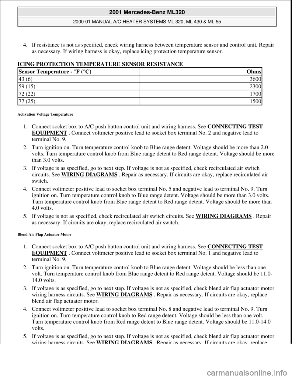
4. If resistance is not as specified, check wiring harness between temperature sensor and control unit. Repair
as necessary. If wiring harness is okay, replace icing protection temperature sensor.
ICING PROTECTION TEMPERATURE SENSOR RESISTANCE
Activation Voltage Temperature
1. Connect socket box to A/C push button control unit and wiring harness. See CONNECTING TEST
EQUIPMENT . Connect voltmeter positive lead to socket box terminal No. 2 and negative lead to
terminal No. 9.
2. Turn ignition on. Turn temperature control knob to Blue range detent. Voltage should be more than 2.0
volts. Turn temperature control knob from Blue range detent to Red range detent. Voltage should be more
than 3.0 volts.
3. If voltage is as specified, go to next step. If voltage is not as specified, check recirculated air switch
circuits. See WIRING DIAGRAMS
. Repair as necessary. If circuits are okay, replace recirculated air
switch.
4. Connect voltmeter positive lead to socket box terminal No. 5 and negative lead to terminal No. 9. Turn
ignition on. Turn temperature control knob to Blue range detent. Voltage should be more than 3.0 volts.
Turn temperature control knob from Blue range detent to Red range detent. Voltage should be more than
4.0 volts.
5. If voltage is not as specified, check recirculated air switch circuits. See WIRING DIAGRAMS
. Repair
as necessary. If circuits are okay, replace recirculated air switch.
Blend Air Flap Actuator Motor
1. Connect socket box to A/C push button control unit and wiring harness. See CONNECTING TEST
EQUIPMENT . Connect voltmeter positive lead to socket box terminal No. 1 and negative lead to
terminal No. 9.
2. Turn ignition on. Turn temperature control knob to Blue range detent. Voltage should be less than one
volt. Turn temperature control knob from Blue range detent to Red range detent. Voltage should be 11.0-
14.0 volts.
3. If voltage is as specified, go to next step. If voltage is not as specified, check blend air flap actuator motor
wiring harness circuits. See WIRING DIAGRAMS
. Repair as necessary. If circuits are okay, replace
blend air flap actuator motor.
4. Connect voltmeter positive lead to socket box terminal No. 8 and negative lead to terminal No. 9. Turn
ignition on. Turn temperature control knob to Red range detent. Voltage should be less than one volt.
Turn temperature control knob from Red range detent to Blue range detent. Voltage should be 11.0-14.0
volts.
5. If voltage is as specified, go to next step. If voltage is not as specified, check blend air flap actuator motor
wiring harness circuits. See WIRING DIAGRAMS
. Repair as necessary. If circuits are okay, replace
Sensor Temperature - °F (°C)Ohms
43 (6)3600
59 (15)2300
72 (22)1700
77 (25)1500
2001 Mercedes-Benz ML320
2000-01 MANUAL A/C-HEATER SYSTEMS ML 320, ML 430 & ML 55
me
Saturday, October 02, 2010 3:25:10 PMPage 12 © 2006 Mitchell Repair Information Company, LLC.
Page 3224 of 4133
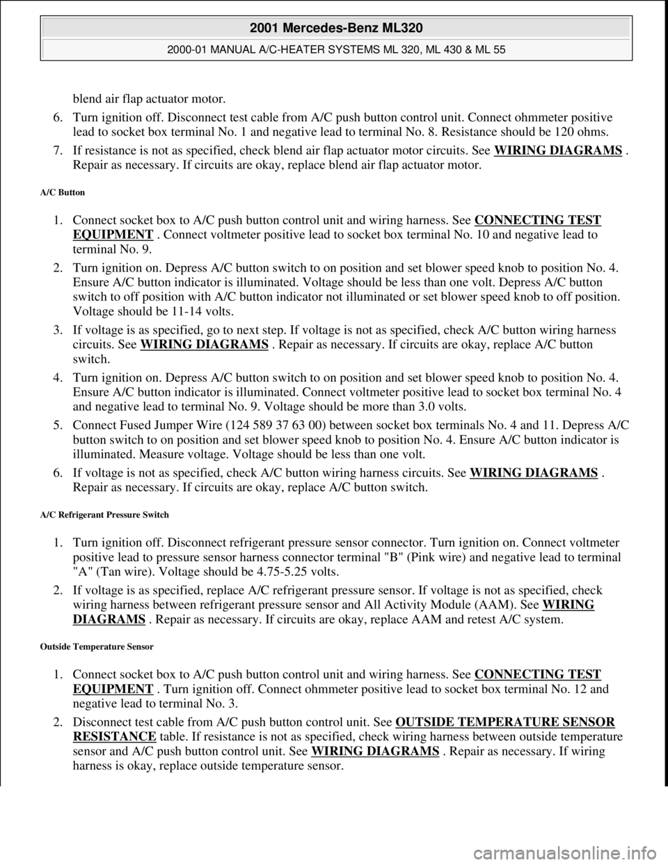
blend air flap actuator motor.
6. Turn ignition off. Disconnect test cable from A/C push button control unit. Connect ohmmeter positive
lead to socket box terminal No. 1 and negative lead to terminal No. 8. Resistance should be 120 ohms.
7. If resistance is not as specified, check blend air flap actuator motor circuits. See WIRING DIAGRAMS
.
Repair as necessary. If circuits are okay, replace blend air flap actuator motor.
A/C Button
1. Connect socket box to A/C push button control unit and wiring harness. See CONNECTING TEST
EQUIPMENT . Connect voltmeter positive lead to socket box terminal No. 10 and negative lead to
terminal No. 9.
2. Turn ignition on. Depress A/C button switch to on position and set blower speed knob to position No. 4.
Ensure A/C button indicator is illuminated. Voltage should be less than one volt. Depress A/C button
switch to off position with A/C button indicator not illuminated or set blower speed knob to off position.
Voltage should be 11-14 volts.
3. If voltage is as specified, go to next step. If voltage is not as specified, check A/C button wiring harness
circuits. See WIRING DIAGRAMS
. Repair as necessary. If circuits are okay, replace A/C button
switch.
4. Turn ignition on. Depress A/C button switch to on position and set blower speed knob to position No. 4.
Ensure A/C button indicator is illuminated. Connect voltmeter positive lead to socket box terminal No. 4
and negative lead to terminal No. 9. Voltage should be more than 3.0 volts.
5. Connect Fused Jumper Wire (124 589 37 63 00) between socket box terminals No. 4 and 11. Depress A/C
button switch to on position and set blower speed knob to position No. 4. Ensure A/C button indicator is
illuminated. Measure voltage. Voltage should be less than one volt.
6. If voltage is not as specified, check A/C button wiring harness circuits. See WIRING DIAGRAMS
.
Repair as necessary. If circuits are okay, replace A/C button switch.
A/C Refrigerant Pressure Switch
1. Turn ignition off. Disconnect refrigerant pressure sensor connector. Turn ignition on. Connect voltmeter
positive lead to pressure sensor harness connector terminal "B" (Pink wire) and negative lead to terminal
"A" (Tan wire). Voltage should be 4.75-5.25 volts.
2. If voltage is as specified, replace A/C refrigerant pressure sensor. If voltage is not as specified, check
wiring harness between refrigerant pressure sensor and All Activity Module (AAM). See WIRING
DIAGRAMS . Repair as necessary. If circuits are okay, replace AAM and retest A/C system.
Outside Temperature Sensor
1. Connect socket box to A/C push button control unit and wiring harness. See CONNECTING TEST
EQUIPMENT . Turn ignition off. Connect ohmmeter positive lead to socket box terminal No. 12 and
negative lead to terminal No. 3.
2. Disconnect test cable from A/C push button control unit. See OUTSIDE TEMPERATURE SENSOR
RESISTANCE table. If resistance is not as specified, check wiring harness between outside temperature
sensor and A/C push button control unit. See WIRING DIAGRAMS
. Repair as necessary. If wiring
harness is okay, replace outside temperature sensor.
2001 Mercedes-Benz ML320
2000-01 MANUAL A/C-HEATER SYSTEMS ML 320, ML 430 & ML 55
me
Saturday, October 02, 2010 3:25:10 PMPage 13 © 2006 Mitchell Repair Information Company, LLC.
Page 3236 of 4133
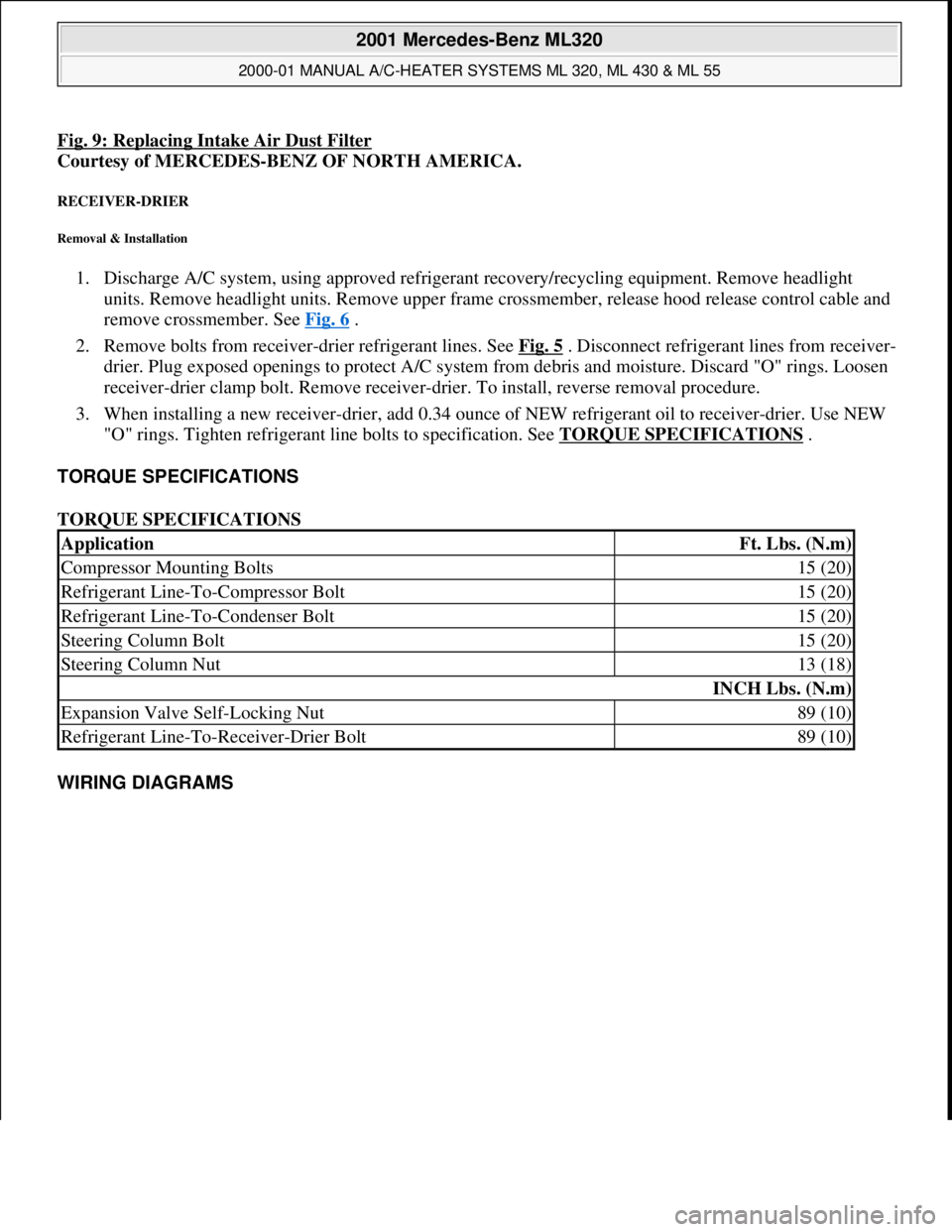
Fig. 9: Replacing Intake Air Dust Filter
Courtesy of MERCEDES-BENZ OF NORTH AMERICA.
RECEIVER-DRIER
Removal & Installation
1. Discharge A/C system, using approved refrigerant recovery/recycling equipment. Remove headlight
units. Remove headlight units. Remove upper frame crossmember, release hood release control cable and
remove crossmember. See Fig. 6
.
2. Remove bolts from receiver-drier refrigerant lines. See Fig. 5
. Disconnect refrigerant lines from receiver-
drier. Plug exposed openings to protect A/C system from debris and moisture. Discard "O" rings. Loosen
receiver-drier clamp bolt. Remove receiver-drier. To install, reverse removal procedure.
3. When installing a new receiver-drier, add 0.34 ounce of NEW refrigerant oil to receiver-drier. Use NEW
"O" rings. Tighten refrigerant line bolts to specification. See TORQUE SPECIFICATIONS
.
TORQUE SPECIFICATIONS
TORQUE SPECIFICATIONS
WIRING DIAGRAMS
ApplicationFt. Lbs. (N.m)
Compressor Mounting Bolts15 (20)
Refrigerant Line-To-Compressor Bolt15 (20)
Refrigerant Line-To-Condenser Bolt15 (20)
Steering Column Bolt15 (20)
Steering Column Nut13 (18)
INCH Lbs. (N.m)
Expansion Valve Self-Locking Nut89 (10)
Refrigerant Line-To-Receiver-Drier Bolt89 (10)
2001 Mercedes-Benz ML320
2000-01 MANUAL A/C-HEATER SYSTEMS ML 320, ML 430 & ML 55
me
Saturday, October 02, 2010 3:25:10 PMPage 25 © 2006 Mitchell Repair Information Company, LLC.
Page 3238 of 4133
Fig. 10: Manual A/C-Heater Systems Wiring Diagram (2000-01 ML 320 Without Cooling Fan Control
Module - 1 Of 2)
2001 Mercedes-Benz ML320
2000-01 MANUAL A/C-HEATER SYSTEMS ML 320, ML 430 & ML 55
me
Saturday, October 02, 2010 3:25:10 PMPage 27 © 2006 Mitchell Repair Information Company, LLC.