high beam MERCEDES-BENZ ML320 1997 Complete Service Manual
[x] Cancel search | Manufacturer: MERCEDES-BENZ, Model Year: 1997, Model line: ML320, Model: MERCEDES-BENZ ML320 1997Pages: 4133, PDF Size: 88.89 MB
Page 1138 of 4133

334 IndexRemote door unlock
With Tele Aid* 179
Remote Vehicle Diagnostics 314
Removing
Vehicle battery 279
Wheel 276
Wiper blades 273
Removing spare wheel 259
Replacing
Backup lamp bulbs 270
Brake lamp bulbs 270
Bulbs 266
Front lamp bulbs 268
Front turn signal bulbs 268
Fuses 287
High beam bulbs 269
High mounted brake lamp 271
License plate lamp bulbs 271
Low beam bulbs 268
Rear fog lamp bulbs 270
Rear lamp bulbs 267, 270
Rear parking lamp bulbs 270
Rear side marker lamp bulbs 270
Rear standing lamp bulbs 270
Rear turn signal bulbs 270
Wiper blades 273Replacing front fog lamp bulb 270
Reporting
Safety defects 19
Resetting
Service indicator (FSS) 233
Trip odometer 118
Residual heat utilization 140, 314
Residual ventilation 140
REST (Residual engine heat
utilization) 314
Restraint system 314
Restraint system see Infant and child re-
straint systems 68, 71
Returning from off-road driving 205
Rims 295
Roadside assistance 12
Tele Aid* 175RON 215
RON (Research Octane Number) 314
Roof rack 163
Rotating wheels 228
Rubber parts
Cleaning 239
S
Safety
Occupant 58
Safety belts see Seat belts 42
Safety defects
Reporting 19
Safety systems
Driving 76
Saving current speed 151
Seat belt force limiter 67
Seat belt height adjustment 45
Page 1141 of 4133
337 Index
Sun visor 132
Supplemental Restraint System
(SRS) 314
Switching off
Automatic climate control 137
ESP 81
Hazard warning flasher 112
Headlamps 54
Rapid seat heating 99
Transmission control – LOW RANGE
mode 125
Switching on
Automatic climate control 137
ESP 82
Front fog lamps 111
Front fog lamps, rear fog lamp 111
Hazard warning flasher 112
Headlamps 48
High beams 110
Rapid seat heating* 98
Seat heating* 98
Transmission control – LOW RANGE
mode 125
Trip computer* 186
Windshield wipers 49Synchronizing
ESP 246
Power windows 146
Remote control 263
Sliding/pop-up roof* 149
T
Tachometer 26, 118
Displaying gear range 121
Tail lamps 270
Cleaning 236
Replacing bulbs 267Tar stains 235
Technical data 302
Brake fluid 302
Coolants 304
Electrical system 297
Engine 294
Engine oil 302
Engine oil additives 302
Fuel requirements 303
Gasoline additives 303
Main dimensions 298
Premium unleaded gasoline 303
Rims and tires 295
Weights 299
Windshield and headlamp washer
system 307
Tele Aid System* 315
Page 1515 of 4133
XENON HEADLAMPS, FUNCTION - GF82.10-P-2007-01GH
Function
The combustion chamber of the xenon lamp is filled with xenon and a mixture of metal halide salts. This
mixture is ignited by high voltage. The color of the light has a characteristic similar to daylight.
When the low beam lamps are switched on the xenon headlamp control module (E1 n1, E2n1) activates the
xenon headlamp control module and ignition module (E1n2, E2n2) via the control voltage within a few
milliseconds.
As a result of a high voltage surge (approx. 20 kV) of the ignition device, an arc forms between the electrodes,
and the xenon lamp is ignited.
When an arc of sufficient stability is detected, the control electronics of the xenon lamp control module (E1n1,
E2n1) switches over to power-limiting mode. The electric power is regulated to 35 W. A voltage converter
generates the voltage of approx. 85 V (~) necessary for the reliable function of the xenon lamp. For technical
reasons the xenon lamp has a timed startup characteristic. After switching on, 50 % of the luminosity is reached
within 1 to 2 seconds and full luminosity is reached after approx. 30 seconds.
Model 163, up to
31.08.01GF82.10-P-0001GH
Model 163 as of
1.09.01GF82.10-P-
0001GHA
Xenon headlamps, functionModel 163, up to
31.08.01GF82.10-P-2007-
01GH
Model 163 as of
1.09.01GF82.10-P-2007-
01GHA
Automatic driving light actuation,
functionModel 163 as of
01.09.01GF82.10-P-3003GH
Daytime running light control, functionModel 163 as of
01.09.01GF82.10-P-3005GH
Locator lighting, functionModel 163 as of
01.09.01GF80.20-P-2008GH
Headlamp cut-in, functionModel 163 as of
01.09.01GF80.20-P-2003GH
Daytime running lights, functionModel 202 with
Code 236a special
lamp circuit for
daytime running
lampsGF82.10-P-2002A
Contents - Function description of
exterior lighting,
location/task/design/functionModels 129, 140,
163, 202, 208, 210
with code 612b
xenon headlamp unitGF82.10-P-9999B
2001 Mercedes-Benz ML320
1998-2005 ACCESSORIES & BODY, CAB Electrical System - Body - 163 Chassis
me
Saturday, October 02, 2010 3:30:04 PMPage 20 © 2006 Mitchell Repair Information Company, LLC.
Page 1516 of 4133
XENON HEADLAMPS, FUNCTION - GF82.10-P-2007-01GHA
The lighting technology, known as bi-xenon 70 , is located in the outer headlamps.
When the low beam lamps are switched on the xenon headlamp control module (E1 n1, E2n1) activates the
xenon headlamp control module and ignition module (E1n2, E2n2) via the control voltage within a few
milliseconds.
A high-voltage surge from the ignition device ignites the xenon lamps, and in doing so an electric arc is formed
between the electrodes. When an arc of sufficient stability is detected, the control electronics of the control
module (E1 n1, E2n1) switches over to power-limiting mode.
The light generated previously in a gas discharge lamp (D2S lamp) is not reflected in bi-xenon 70 headlamps,
but instead it is sent directly through a lens optical system with a lens diameter of 70 mm.
Using the mask (B), which is positioned between the gas discharge lamp and the lens optical system, the beam
of light is partially masked for the low beam so that oncoming traffic is not blinded.
For the high beam, the mask (B) is electro-mechanically folded to the side using the solenoid (M).
If the solenoid (M) should fail or a supply line breaks, the mask (B) remains mechanically held in the low
beam position, always between the gas discharge lamp and the lens optical system.
In order to make the extremely bright light more acceptable to other road users, the lens aperture area with its
dotted characteristic is optically enlarged.
This is possible on account of the specially formed areas which surround the lens. In addition, the light can pass
through a number of chrome-plated strips from the rear. A portion of the diffused light is intercepted by the
lower section of the surface area and reflected to the upper section of the chrome-plated longitudinal strips.
For technical reasons the xenon lamp has a timed startup characteristic. After switch on, 50 % of the luminosity
is reached within 1 to 2 seconds and full luminosity is achieved after another approx. 30 seconds.
XENON HEADLAMP, LOCATION/DESIGN/FUNCTION - GF82.10-P-2007GH
MODELS 163.113 /136 /154 /172 up to 31.08.01 with CODE (612b) xenon headlamp unit with CODE
(U47) conversion package
MODELS 163.174 up to 31.08.01, 163.113 /128 /136 /154 /172 as of 01.09.01
Design:
From model
year 2002 (as of 1.9.01) the xenon headlamps are installed as standard.
2001 Mercedes-Benz ML320
1998-2005 ACCESSORIES & BODY, CAB Electrical System - Body - 163 Chassis
me
Saturday, October 02, 2010 3:30:04 PMPage 21 © 2006 Mitchell Repair Information Company, LLC.
Page 1520 of 4133

during the day only the low beam is on
when dark, the side lamps, license plate lamps as well as the switch and controls illumination (circuit
58d) are switched on
With halogen headlights the low beam is operated during the day with a reduced voltage
The lighting switches off automatically if the gearshift lever remains in "P" or "N" position for more than
3 min
Scandinavia
with daytime running lamps the low beam, the side lamps and the license plate lamps are active
the daytime running lamps switch off if the light switch assumes the "side lamps ON" position
Other countries
with daytime running lamps the low beam, the side lamps and the license plate lamps are active
the daytime running lamps are always active
The high beams can only be switched on if the exterior lamp switch:
is at "low beam"
is at "AUTO" and "Darkness" is detected
daytime running lamps for "Other countries" has been coded
CONTENTS - FUNCTION DESCRIPTION OF EXTERIOR LIGHTING, LOCATION/ PURPOSE/DESIGN/FUNCTION -
GF82.10-P-9999B
MODELS 129, 140, 202, 208, 210, 163 up to 31.08.01 with CODE (612b) xenon headlamp unit
MODEL 163 as of 01.09.01 with CODE (614) bi-xenon headlamp unit
Automatic driving light
actuation, function GF82.10-P-3003GH
Table of contents,
function description for
exterior lighting GF82.10-P-0999A
Axle sensor for headlamp range
adjustment, location/taskMODELS 129, 140,
202, 208, 210 with
code 612b xenon
headlamp unitGF82.10-P-2100A
Headlamp range adjustment motor,
location/ taskMODELS 129, 140,
202, 208, 210 with
code 612b xenon
headlamp unitGF82.10-P-2101A
2001 Mercedes-Benz ML320
1998-2005 ACCESSORIES & BODY, CAB Electrical System - Body - 163 Chassis
me
Saturday, October 02, 2010 3:30:04 PMPage 25 © 2006 Mitchell Repair Information Company, LLC.
Page 1543 of 4133
How it works
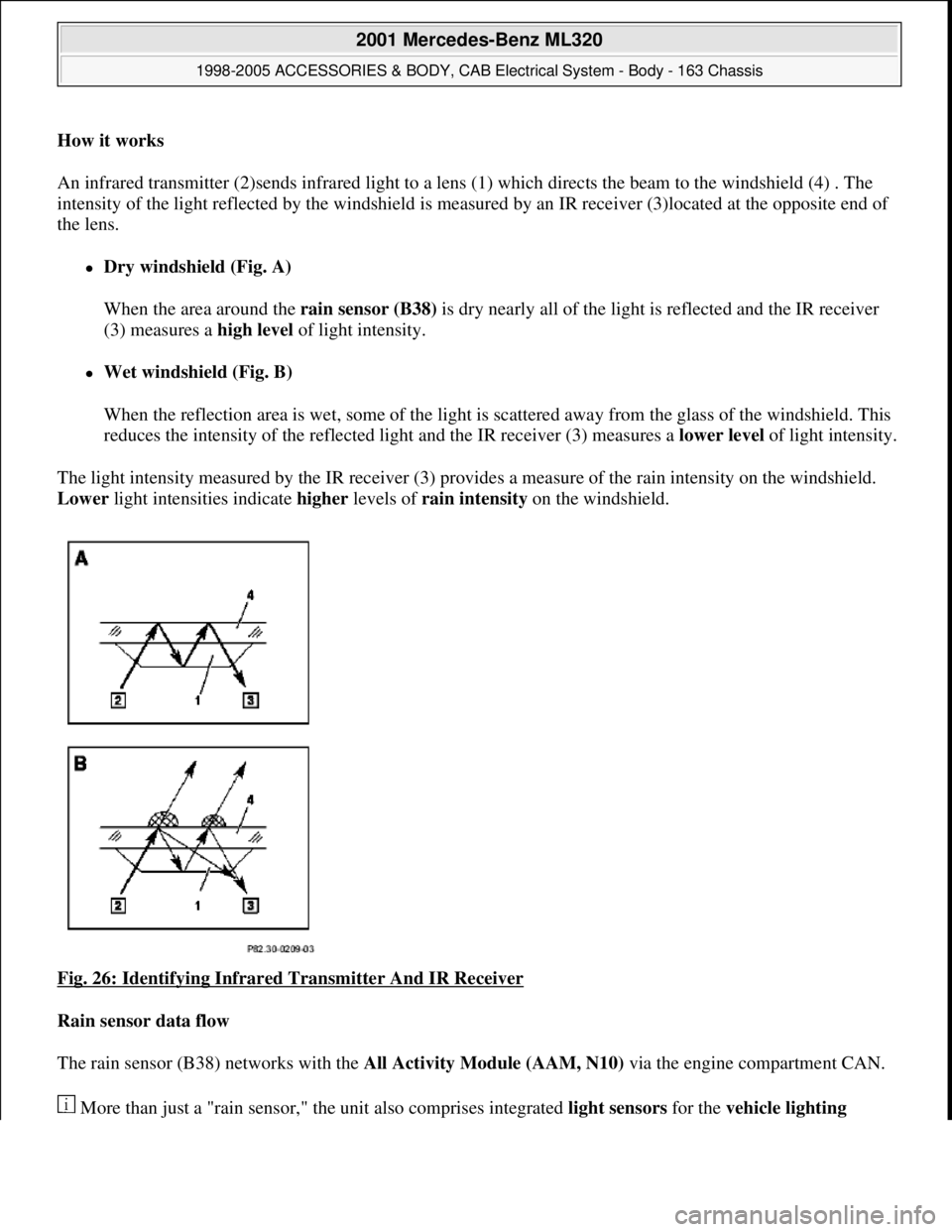
An infrared transmitter (2)sends infrared light to a lens (1) which directs the beam to the windshield (4) . The
intensity of the light reflected by the windshield is measured by an IR receiver (3)located at the opposite end of
the lens.
Dry windshield (Fig. A)
When the area around the rain sensor (B38) is dry nearly all of the light is reflected and the IR receiver
(3) measures a high level of light intensity.
Wet windshield (Fig. B)
When the reflection area is wet, some of the light is scattered away from the glass of the windshield. This
reduces the intensity of the reflected light and the IR receiver (3) measures a lower level of light intensity.
The light intensity measured by the IR receiver (3) provides a measure of the rain intensity on the windshield.
Lower light intensities indicate higher levels of rain intensity on the windshield.
Fig. 26: Identifying Infrared Transmitter And IR Receiver
Rain sensor data flow
The rain sensor (B38) networks with the All Activity Module (AAM, N10) via the engine compartment CAN.
More than
just a "rain sensor," the unit also comprises integrated light sensors for the vehicle lighting
2001 Mercedes-Benz ML320
1998-2005 ACCESSORIES & BODY, CAB Electrical System - Body - 163 Chassis
me
Saturday, October 02, 2010 3:30:04 PMPage 48 © 2006 Mitchell Repair Information Company, LLC.
Page 1660 of 4133

Consult a physician immediately.
Always consult a medical service or physician after administering first aid.
INJURY HAZARD FROM PINCHING AND CRUSHING, IN EXTREME CASES EXTREMITIES CAN EVEN BE CUT OFF
WHEN CAUGHT IN WINDSHIELD WIPER MECHANISM. - AS82.30-Z-0001-01A
Always remove ignition key before working on windshield wiper mechanism.
Injury hazard
When working in the area of the windshield wiper mechanism with the ignition key in position "1" or "2" the
wiper arm or wiper linkage can be pushed out of its end position and start running unintentionally . This can
result in severe injuries by cutting, pinching or crushing body parts.
Rules of behavior/protective measures
Always remove ignition key before working on windshield wiper mechanism.
Secure operating range of mechanism against reaching in.
Keep sufficient distance away from moving parts.
Supervise hazard area.
Wear tight fitting clothing and hair net.
TROUBLE DIAGNOSIS
HIGH BEAMS AND/OR LOW BEAMS DO NOT WORK - AF82.10-P-2009B
MODEL 129,140,163,170, 202, 208, 210, 215, 220 with CODE (612) Xenon headlamp unit
Modification notes
4.4.00Supersedes STIP 82.10-
019 from 24.03.2000
Damage codeCauseRemedy
Risk of death caused
by high voltage levels
present at xenon
headlamps.
Risk of explosion/risk
of fire caused by highly
inflammable substances
at damaged xenon bulbs
Risk of injury caused
by UV light, hot
components at xenon Do not come into contact with
parts that are under high voltage.
Persons with active electronic
implants (e.g. heart pacemakers)
must never work on xenon
headlamps. Switch off the
complete lighting system. Wear
insulated safety shoes, safety
glasses and protective gloves.
Remove highly inflammable
materials from the hazard area. AS82.10-Z-0001-01A
2001 Mercedes-Benz ML320
1998-2005 ACCESSORIES & BODY, CAB Electrical System - Body - 163 Chassis
me
Saturday, October 02, 2010 3:30:06 PMPage 165 © 2006 Mitchell Repair Information Company, LLC.
Page 1817 of 4133

Front seats
Seat belts/emergency tensioning retractors
MAINTENANCE
CHECK SETTING OF HIGH BEAM - AP82.10-P-8260-02A
1. The light focal point should be located on the relevant central mark (6). In the event of a deviation: Check
seat of bulb.
Fig. 221: Identifying Central Mark
SET OR INSPECT FOG LAMPS - AP82.10-P-8260-04A
1. The light-dark boundary must be as horizontal as possible at the height of the appropriate dividing line
(4), correct if necessary.
2. For model 140 sedan as of approx. 03.94, 168 and 202: Check seat of bulb.
10.2Install E-call control
module (A35/8) with
bracket Only with emergency call
system E-Call, code 349.AR82.95-P-0008GH
*BA91.10-P-1001-01B
*BA91.40-P-1001-01D
11Install center console AR68.20-P-2000GH
12Install radio (A2) AR82.60-P-7502EA
NumberDesignationModel Series 163
BA91.10-P-1001-01BBolt of seating mounting
bracket to vehicle floorNm40
NumberDesignation
Model 163 up to
08/99Model 163 as of
09/99
BA91.40-P-1001-
01DScrew on belt end
fittingNm3535
2001 Mercedes-Benz ML320
1998-2005 ACCESSORIES & BODY, CAB Electrical System - Body - 163 Chassis
me
Saturday, October 02, 2010 3:30:10 PMPage 322 © 2006 Mitchell Repair Information Company, LLC.
Page 1820 of 4133
Workshop equipment
WINDSHIELD WASHER - CHECKING AND CORRECTING FLUID LEVEL - AP82.35-P-8210GH
MODEL 163
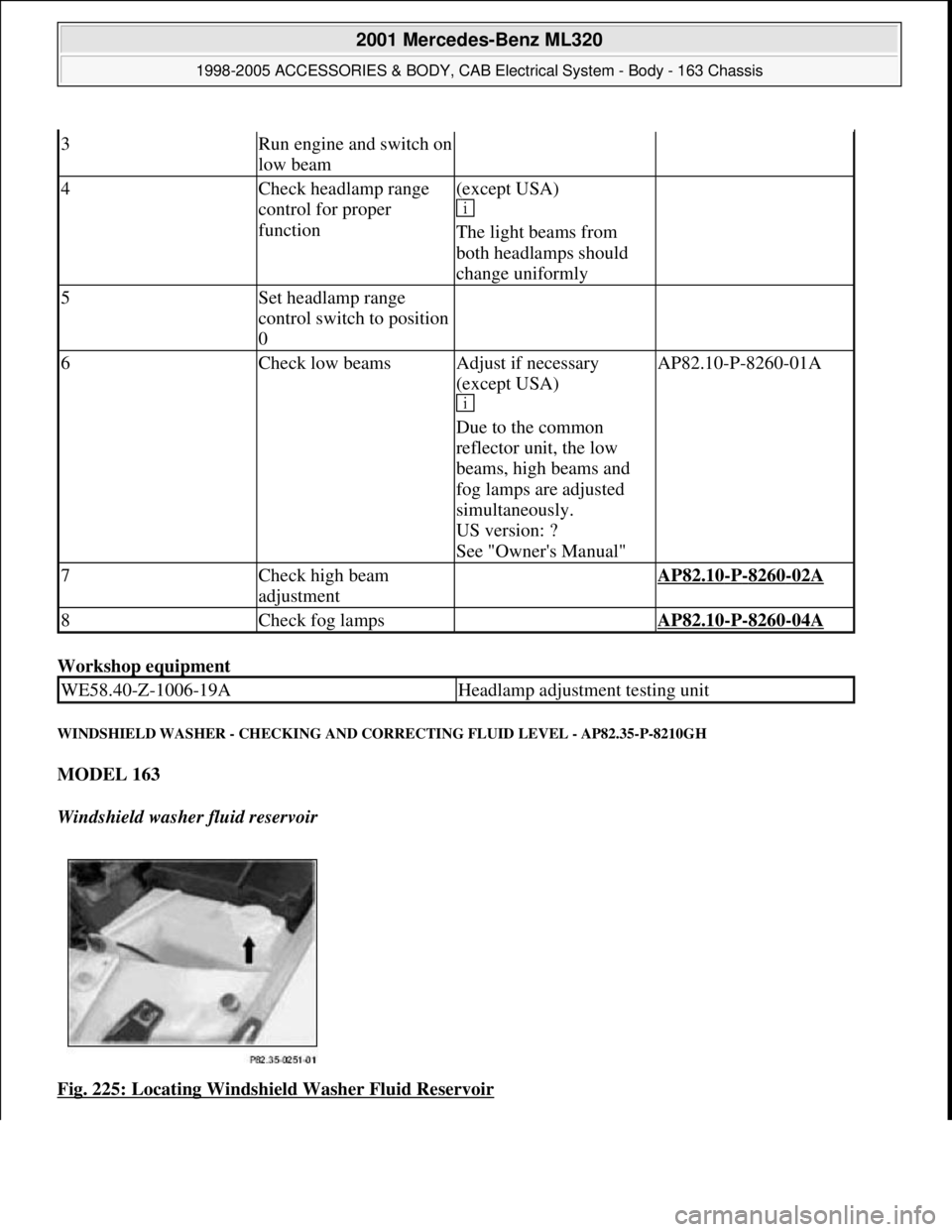
Windshield washer fluid reservoir
Fig. 225: Locating Windshield Washer Fluid Reservoir
3Run engine and switch on
low beam
4Check headlamp range
control for proper
function(except USA)
The light beams from
both headlamps should
change uniformly
5Set headlamp range
control switch to position
0
6Check low beamsAdjust if necessary
(except USA)
Due to the common
reflector unit, the low
beams, high beams and
fog lamps are adjusted
simultaneously.
US version: ?
See "Owner's Manual"AP82.10-P-8260-01A
7Check high beam
adjustment AP82.10-P-8260-02A
8Check fog lamps AP82.10-P-8260-04A
WE58.40-Z-1006-19AHeadlamp adjustment testing unit
2001 Mercedes-Benz ML320
1998-2005 ACCESSORIES & BODY, CAB Electrical System - Body - 163 Chassis
me
Saturday, October 02, 2010 3:30:10 PMPage 325 © 2006 Mitchell Repair Information Company, LLC.
Page 1970 of 4133
AP82.10-P-8260GH
Check and correct headlamp adjustment
2.7.97
MODEL
163
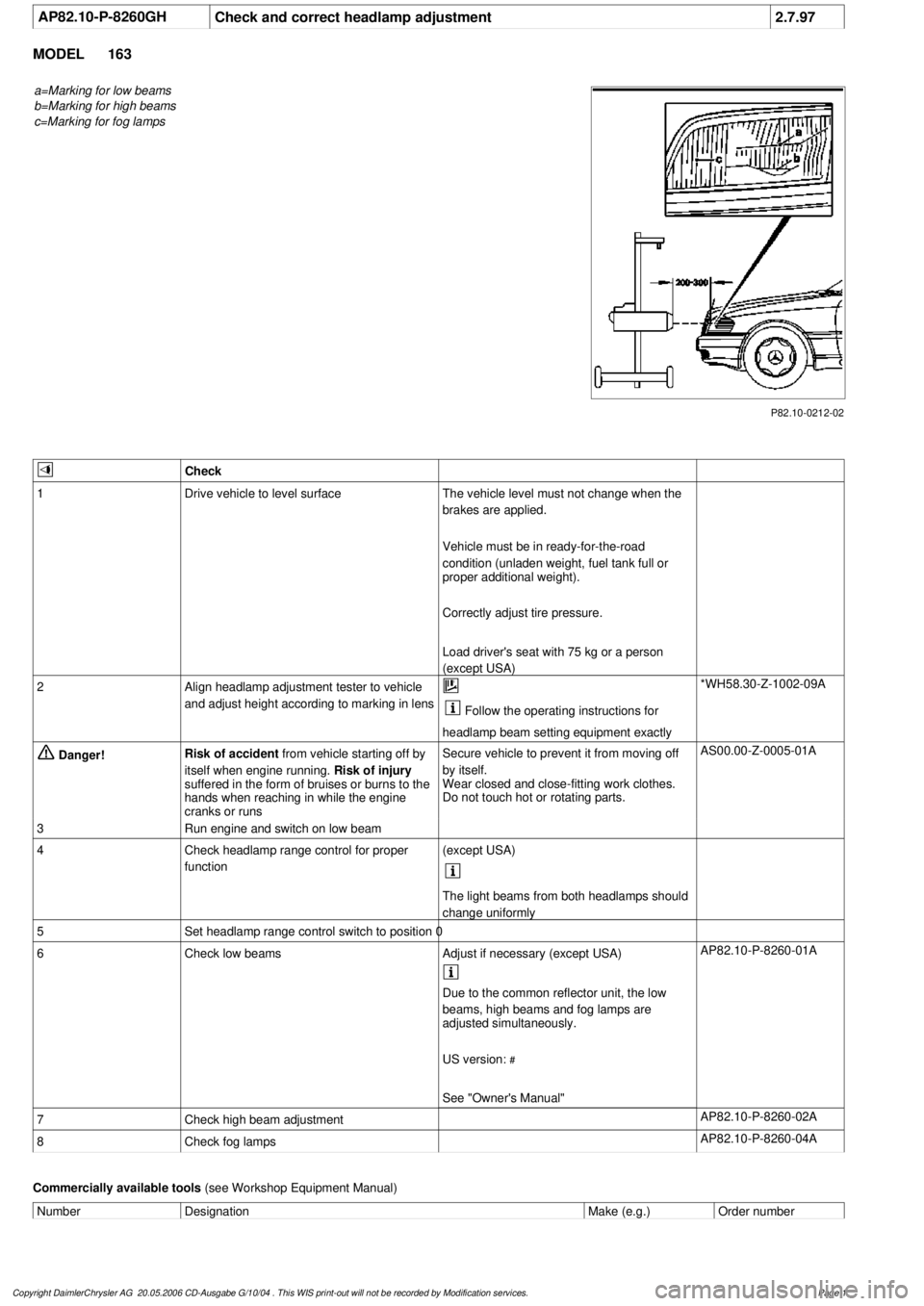
a=Marking for low beams
b=Marking for high beams
c=Marking for fog lamps
P82.10-0212-02
Check
1
Drive vehicle to level surface
The vehicle level must not change when the
brakes are applied.
Vehicle must be in ready-for-the-road
condition (unladen weight, fuel tank full or
proper additional weight).
Correctly adjust tire pressure.
Load driver's seat with 75 kg or a person
(except USA)
2
Align headlamp adjustment tester to vehicle
and adjust height according to marking in lens
Follow the operating instructions for
headlamp beam setting equipment exactly
*WH58.30-Z-1002-09A
Danger!
Risk of accident
from vehicle starting off by
itself when engine running.
Risk of injury
suffered in the form of bruises or burns to the
hands when reaching in while the engine
cranks or runs
Secure vehicle to prevent it from moving off
by itself.
Wear closed and close-fitting work clothes.
Do not touch hot or rotating parts.
AS00.00-Z-0005-01A
3
Run engine and switch on low beam
4
Check headlamp range control for proper
function
(except USA)
The light beams from both headlamps should
change uniformly
5
Set headlamp range control switch to position 0
6
Check low beams
Adjust if necessary (except USA)
AP82.10-P-8260-01A
Due to the common reflector unit, the low
beams, high beams and fog lamps are
adjusted simultaneously.
US version:
#
See "Owner's Manual"
7
Check high beam adjustment
AP82.10-P-8260-02A
8
Check fog lamps
AP82.10-P-8260-04A
Commercially available tools
(see Workshop Equipment Manual)
Number
Designation
Make (e.g.)
Order number
Copyright DaimlerChrysler AG 20.05.2006 CD-Ausgabe G/10/04 . This WIS print-out will not be recorde
d by Modification services.
Page 1