oil MERCEDES-BENZ ML320 1997 Complete Repair Manual
[x] Cancel search | Manufacturer: MERCEDES-BENZ, Model Year: 1997, Model line: ML320, Model: MERCEDES-BENZ ML320 1997Pages: 4133, PDF Size: 88.89 MB
Page 3819 of 4133

AR91.40-P-0681GI
Remove/install rear seat belts
16.4.99
MODEL
163.136 /154 /172 as of 1.9.99,
163.113 /128 /157 /174 /175
1
Bolt
2
Seat belt guide bracket
3
Bolt
4
Automatic belt retractor
5
Belt height adjuster
R12/7
Right rear ETR ignition squib
P91.40-2114-03
Remove/Install
Danger!
Risk of injury
when carrying out test or repair
work on airbag or emergency tensioning
retractor units
Store airbags with exit surface pointing
upward, do not expose to temperatures above
100 °C. Interrupt power supply when working
on such units.
AS91.00-Z-0001-01A
Danger!
The spring in the inertia reel can pose an
injury hazard
when the tension is released
and it uncoils.
Never disassemble inertia reels
AS91.00-Z-0002-01A
Important instructions for performing repair,
body work and welding on vehicles with
airbags or belt tensioner units
Models 129 as of 1.7.93, 163, 168, 170, 202
as of 1.7.93, 208, 210, 414, 638, 690.6, 901,
902, 903, 904, 905
Model 461 with engine 602.983
Model 463 up to 30.11.00
MODELS WD141, WD241, WD341, WD641,
WD741, XD141, XD241, XD341, XD441,
XD541, XD641, XD741, YD141, YD241,
YD341, YD441, YD541, YD641, YD741
AH91.00-P-0002-01B
Evaluation of airbags and emergency
tensioning retractors on accident vehicles
Model 129 as of 1.7.93, 163, 168, 170, 202 as
of 1.7.93, 203, 208, 209, 210,
211.004/006/016/061/065/070, 215, 220, 230,
240, 414, 463, 638, 901, 902, 903, 904, 905
Models WD141, WD241, WD341, WD641,
WD741, XD141, XD241, XD341, XD441,
XD541, XD641, XD741, YD141, YD241,
YD341, YD441, YD541, YD641, YD741
AH91.00-P-0006-01B
Legal regulations concerning the handling
and storage of airbag and emergency
tensioning retractors
Models 124, 129, 140, 163, 168, 170, 202,
203, 208, 209, 210,
211.004/006/016/061/065/070, 215, 220, 230,
240, 314, 316, 318, 414, 461, 463, 638, 668,
670, 690.6, 901, 902, 903, 904, 905, 950,
952, 953, 954, 970, 972, 974, 975, 976
Models WD141, WD241, WD341, WD641,
WD741, XD141, XD241, XD341, XD441,
XD541, XD641, XD741, YD141, YD241,
YD341, YD441, YD541, YD641, YD741
AH91.00-P-0004-01A
o
Notes on disposal of airbags and emergency
tensioning retractors
All models
OS91.00-P-0001-01A
Render emergency tensioning retractors
unusable
AR91.40-P-0611A
1
Withdraw ignition key
2
Remove paneling on C-pillar
AR68.30-P-4490GH
Copyright DaimlerChrysler AG 14.06.2006 CD-Ausgabe G/10/04 . This WIS print-out will not be recorde
d by Modification services.
Page 1
Page 3820 of 4133

3
Unscrew bolt (1) from seat belt guide bracket
(2)
If necessary, remove belt height adjuster
(5).
*BA91.40-P-1002-01D
4
Disconnect connector from right rear ETR
[GUS] ignition squib (R12/7)
5
Unscrew bolt (3) from automatic belt retractor
(4)
*BA91.40-P-1003-01D
6
Detach automatic belt retractor (4)
The automatic belt retractor must not be
disassembled.
Never use oil or grease to eliminate noises.
7
Check seat belts for damage
e
Check seat belts for damage
AP91.40-P-9150GH
8
Install in the reverse order
Installation:
Pay attention to different
version (left/ right) of emergency tensioning
retractors and satisfactory seating in the
locking device.
9
Read fault memory and erase
10Carry out diagnosis
see Diagnosis Manual.
Seat belts/emergency tensioning retractors
Number
Designation
Model 163 up to
08/99
Model 163 as of
09/99
BA91.40-P-1002-01D
Screw in rear upper belt guide fitting
Nm
3030
BA91.40-P-1003-01D
Bolt to rear inertia reel
Nm
3030
Copyright DaimlerChrysler AG 14.06.2006 CD-Ausgabe G/10/04 . This WIS print-out will not be recorde
d by Modification services.
Page 2
Page 3825 of 4133

AR91.40-P-0683GI
Remove, replace and install rear center seat belt
4.5.99
MODELS
163.136 /154 /172 as of 1.9.99,
163.113 /128 /157 /174 /175
P91.40-2170-09
Remove/Install
Danger!
The spring in the inertia reel can pose an
injury hazard
when the tension is released
and it uncoils.
Never disassemble inertia reels
AS91.00-Z-0002-01A
1.1
Disconnect connector from electrical line of
seat belt buckle of the outer rear seat
Only with side airbag in the rear (left and
right), code 293.
Turn ignition key into position "0" in order to
avoid fault codes.
2
Unhook rear seat cover on the back of the
rear seat cushion
3
Carefully lift up rear seat cover and unscrew
bolt from belt end fitting
Do not damage rear seat cover.
Installation:
Align rear seat cushion and
rear seat cover correctly.
*BA91.40-P-1001-01D
Torx bit set
*000589011000
4
Remove belt end fitting from rear seat
5
Detach paneling (1) of belt guide (2) from rear
backrest
Lift up front paneling and remove
6
Unscrew mounting screws of belt guide and
remove belt guide (2)
7
Fold rear backrest forwards
See Operating Instructions
8
Unhook rear backrest cover (3) on the back of
the rear backrest
9
Unscrew bolts (5) of rear wall paneling (4)
10
Remove rear wall covering (4)
Pull at the upper corners of the rear wall
paneling in order to remove
body-bound rivets (10).
Installation:
Replace body-bound rivets.
11
Unscrew bolt (6) from automatic belt retractor
(7)
*BA91.40-P-1005-01D
Torx bit set
*000589011000
12
Detach automatic belt retractor (7) and guide
seat belt through the rear backrest cover of
the rear backrest
Installation:
Pay attention to catch and
correct installation position of the automatic
belt retractor. Make sure seat belt is not
twisted when installed.
Copyright DaimlerChrysler AG 14.06.2006 CD-Ausgabe G/10/04 . This WIS print-out will not be recorde
d by Modification services.
Page 1
Page 3835 of 4133
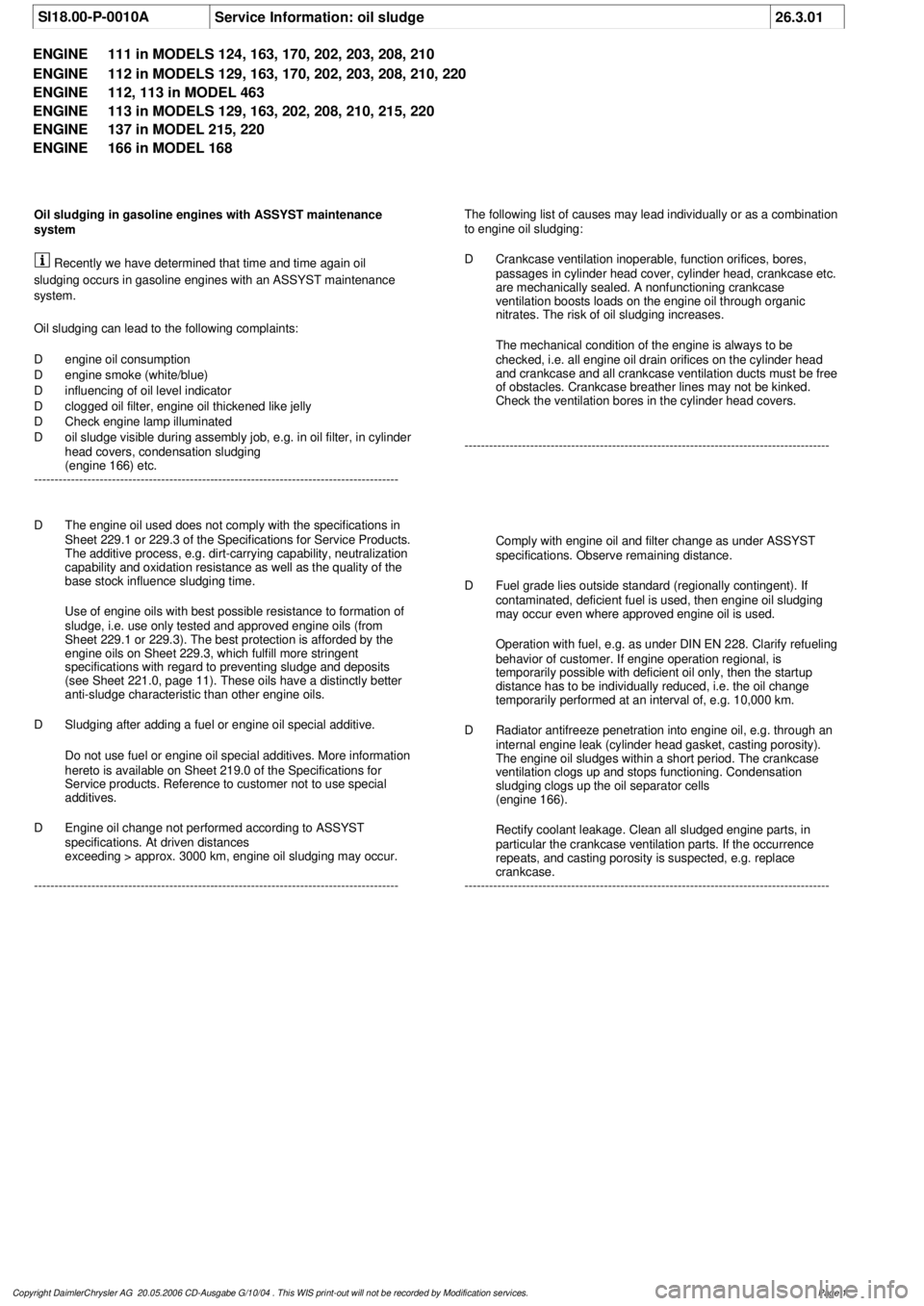
SI18.00-P-0010A
Service Information: oil sludge
26.3.01
ENGINE
111 in MODELS 124, 163, 170, 202, 203, 208, 210
ENGINE
112 in MODELS 129, 163, 170, 202, 203, 208, 210, 220
ENGINE
112, 113 in MODEL 463
ENGINE
113 in MODELS 129, 163, 202, 208, 210, 215, 220
ENGINE
137 in MODEL 215, 220
ENGINE
166 in MODEL 168
Oil sludging in gasoline engines with ASSYST maintenance
system
Recently we have determined that time and time again oil
sludging occurs in gasoline engines with an ASSYST maintenance
system.
Oil sludging can lead to the following complaints:
D
engine oil consumption
D
engine smoke (white/blue)
D
influencing of oil level indicator
D
clogged oil filter, engine oil thickened like jelly
D
Check engine lamp illuminated
D
oil sludge visible during assembly job, e.g. in oil filter, in cylinder
head covers, condensation sludging
(engine 166) etc.
-----------------------------------------------------------------------------------------
The following list of causes may lead individually or as a combination
to engine oil sludging:
D
Crankcase ventilation inoperable, function orifices, bores,
passages in cylinder head cover, cylinder head, crankcase etc.
are mechanically sealed. A nonfunctioning crankcase
ventilation boosts loads on the engine oil through organic
nitrates. The risk of oil sludging increases.
The mechanical condition of the engine is always to be
checked, i.e. all engine oil drain orifices on the cylinder head
and crankcase and all crankcase ventilation ducts must be free
of obstacles. Crankcase breather lines may not be kinked.
Check the ventilation bores in the cylinder head covers.
-----------------------------------------------------------------------------------------
D
The engine oil used does not comply with the specifications in
Sheet 229.1 or 229.3 of the Specifications for Service Products.
The additive process, e.g. dirt-carrying capability, neutralization
capability and oxidation resistance as well as the quality of the
base stock influence sludging time.
Use of engine oils with best possible resistance to formation of
sludge, i.e. use only tested and approved engine oils (from
Sheet 229.1 or 229.3). The best protection is afforded by the
engine oils on Sheet 229.3, which fulfill more stringent
specifications with regard to preventing sludge and deposits
(see Sheet 221.0, page 11). These oils have a distinctly better
anti-sludge characteristic than other engine oils.
D
Sludging after adding a fuel or engine oil special additive.
Do not use fuel or engine oil special additives. More information
hereto is available on Sheet 219.0 of the Specifications for
Service products. Reference to customer not to use special
additives.
D
Engine oil change not performed according to ASSYST
specifications. At driven distances
exceeding > approx. 3000 km, engine oil sludging may occur.
-----------------------------------------------------------------------------------------
Comply with engine oil and filter change as under ASSYST
specifications. Observe remaining distance.
D
Fuel grade lies outside standard (regionally contingent). If
contaminated, deficient fuel is used, then engine oil sludging
may occur even where approved engine oil is used.
Operation with fuel, e.g. as under DIN EN 228. Clarify refueling
behavior of customer. If engine operation regional, is
temporarily possible with deficient oil only, then the startup
distance has to be individually reduced, i.e. the oil change
temporarily performed at an interval of, e.g. 10,000 km.
D
Radiator antifreeze penetration into engine oil, e.g. through an
internal engine leak (cylinder head gasket, casting porosity).
The engine oil sludges within a short period. The crankcase
ventilation clogs up and stops functioning. Condensation
sludging clogs up the oil separator cells
(engine 166).
Rectify coolant leakage. Clean all sludged engine parts, in
particular the crankcase ventilation parts. If the occurrence
repeats, and casting porosity is suspected, e.g. replace
crankcase.
-----------------------------------------------------------------------------------------
Copyright DaimlerChrysler AG 20.05.2006 CD-Ausgabe G/10/04 . This WIS print-out will not be recorde
d by Modification services.
Page 1
Page 3836 of 4133
Measures for slightly sludged engine:
Oil and filter change. Purge engine, i.e. normal engine operation
in neutral, or while driving, using oil from Sheet 229.3, 228.3, or
228.5. Drain off scavenging oil after purging process (approx. 1
hour). Repeat purging process if necessary. Refill using engine oil
from Sheet 229.3, or 229.1. The first oil change after clearing the
sludge should be performed after approx. 10,000 km or beforehand;
when doing so use engine oil from Sheet 229.3.
Measures for severely sludged engine:
Engines with severe oil sludging and caking onto engine parts
and into bores have to be dismantled and mechanically cleaned.
Tough sludge residue must not enter the clean side of the oil circuit,
as otherwise, e.g. the piston oil spray and the hydraulic
compensation elements may have their functionality impaired. Refill
using engine oil from Sheet 229.3, or 229.1.
The first oil change after sludging should be performed after approx.
10,000 km; when doing so use engine oil from
Sheet 229.3.
Warranty/goodwill regulations
If in combination with engine oil sludging a warranty/goodwill claim is
submitted, then a regular documentation of maintenance must be
presented. The ASSYST printout is to be filed carefully for further
reference.
Oil sludging in combination with an exceeded oil change interval, or
because of special additives in the fuel/engine oil are costs to be
borne by the customer.
Copyright DaimlerChrysler AG 20.05.2006 CD-Ausgabe G/10/04 . This WIS print-out will not be recorde
d by Modification services.
Page 2
Page 3877 of 4133

Fig. 22: Identifying Engine Control System Lubricate Joints
THROTTLE CONTROL - CHECK CONTROL CABLE FOR SMOOTH OPERATION - AP30.10-P-3024GH
ENGINE 612.963 in MODEL 163.113
ENGINE 628.963 in MODEL 163.128
ENGINE 111.977 in MODEL 163.136
ENGINE 112.942 in MODEL 163.154
ENGINE 112.970 in MODEL 163.157
ENGINE 113.942 in MODEL 163.172
ENGINE 113.981 in MODEL 163.174
ENGINE 113.965 in MODEL 163.175
Inspect
1Oil joint areas of throttle control, inspect for
ease of operation and wear Engine oil conforming to Specifications for
Operating Fluids sheet 226.0-228.3
(all except ) and 236.6/7/9 ( )
Inspect
1Slowly depress accelerator with your foot as
far as the stop and release again Pay attention to freedom of
movement. If any jolting is noticeable: ?
Replace accelerator control cable
Remove/install throttle control cable
Model 163.136 with Engine 111.977AR30.10-P-
3400GA
Model 163.113 with Engine
612.963,
Model 163.128 with Engine 628.963,
2001 Mercedes-Benz ML320
1998-2005 ACCESSORIES & BODY CAB Throttle Control, Speed Control Systems - 163 Chassis
me
Saturday, October 02, 2010 3:36:28 PMPage 37 © 2006 Mitchell Repair Information Company, LLC.
Page 3883 of 4133
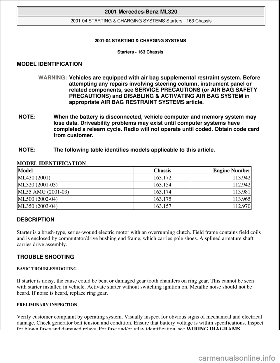
2001-04 STARTING & CHARGING SYSTEMS Starters - 163 Chassis
MODEL IDENTIFICATION
MODEL IDENTIFICATION
DESCRIPTION
Starter is a brush-type, series-wound el ectric motor with an overrunning clutch. Field frame contains field coils
and is enclosed by commutator/drive bushing end frame, which carries pole shoes. A splined armature shaft
carries drive assembly.
TROUBLE SHOOTING
BASIC TROUBLESHOOTING
If starter is noisy, the cause could be bent or damaged gear tooth chamfers on ring gear. This cannot be seen
with starter installed in ve hicle. Activate starter without switching ignition on. Me tallic noise should not be
heard. If noise is he ard, replace ring gear.
PRELIMINARY INSPECTION
Verify customer complaint by operating system. Visually inspect for obvious signs of mechanical and electrical
damage. Check generator belt tension and condition. Ensure that battery voltage is within specifications. Inspect
for blown fuses and damaged relays. For fuse and/or relay identification, see WIRING DIAGRAMS
.
WARNING:
Vehicles are equipped with air bag supplemental restraint system. Before
attempting any repairs involving steer ing column, instrument panel or
related components, see SERVICE PRECAUTIONS (or AIR BAG SAFETY
PRECAUTIONS) and DISABLING & ACTIVATING AIR BAG SYSTEM in
appropriate AIR BAG REST RAINT SYSTEMS article.
NOTE: When the battery is di sconnected, vehicle computer and memory system may
lose data. Driveability problems may exist until computer systems have
completed a relearn cycle. Radio will not operate until coded. Obtain code card
from customer.
NOTE: The following table identifies mo dels applicable to this article.
ModelChassisEngine Number
ML430 (2001)163.172113.942
ML320 (2001-03)163.154112.942
ML55 AMG (2001-03)163.174113.981
ML500 (2002-04)163.175113.965
ML350 (2003-04)163.157112.970
2001 Mercedes-Benz ML320
2001-04 STARTING & CHARGING SYSTEMS Starters - 163 Chassis
2001 Mercedes-Benz ML320
2001-04 STARTING & CHARGING SYSTEMS Starters - 163 Chassis
me
Saturday, October 02, 2010 3:19:47 PMPage 1 © 2006 Mitchell Repair Information Company, LLC.
me
Saturday, October 02, 2010 3:19:50 PMPage 1 © 2006 Mitchell Repair Information Company, LLC.
Page 3898 of 4133
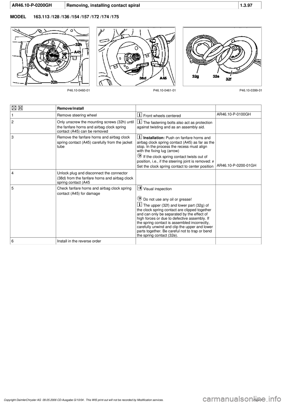
AR46.10-P-0200GH
Removing, installing contact spiral
1.3.97
MODEL
163.113 /128 /136 /154 /157 /172 /174 /175
P46.10-0460-01 P46.10-0461-01 P46.10-0399-01
Remove/install
1
Remove steering wheel
Front wheels centered
AR46.10-P-0100GH
2
Only unscrew the mounting screws (32h) until
the fanfare horns and airbag clock spring
contact (A45) can be removed
The fastening bolts also act as protection
against twisting and as an assembly aid.
3
Remove the fanfare horns and airbag clock
spring contact (A45) carefully from the jacket
tube
Installation:
Push on fanfare horns and
airbag clock spring contact (A45) as far as the
stop. In the process the recess must align
with the fixing lug (arrow)
If the clock spring contact twists out of
position, i.e., if the steering joint is removed:
#
Set the clock spring contact to center position
AR46.10-P-0200-01GH
4
Unlock plug and disconnect the connector
(38d) from the fanfare horns and airbag clock
spring contact (A45
5
Check fanfare horns and airbag clock spring
contact (A45) for damage
Visual inspection
Do not use any oil or grease!
The upper (32f) and lower part (32g) of
the clock spring contact are clipped together
and can only be separated by the effect of
high forces or due to defective assembly. If
the spring contact is assembled incorrectly,
carefully unwind and clip the upper and lower
parts together. Be careful not to trap or bend
the spring contact (32e).
6
Install in the reverse order
Copyright DaimlerChrysler AG 09.05.2006 CD-Ausgabe G/10/04 . This WIS print-out will not be recorde
d by Modification services.
Page 1
Page 3909 of 4133

1998-2005 SUSPENSION
Suspension - 163 Chassis
GENERAL INFORMATION
GENERAL NOTES ON WORKING ON VEHICLES WITH LEVEL CONTROL/ADS - AH32.00-P-0002-01A
All models with code 216b, 216c, 217a, 480
Fig. 1: Identifying Box Wrench (116 589 00 17 00)
The following instructions should be followed when disconnecting and connecting pressure lines:
Clean contaminated line connections before disconnecting them. Seal disconnected lines and hoses and
connections to components immediately with blind plugs.
Only use open box wrench and special tool when loosening and tightening pressure lines to avoid damage to the
line connections.
Check the component concerned and line connections for leaks after assembly work on the suspension
system.
NOTES ON CHECKING OIL LEVEL ON VEHICLES WITH LEVEL CONTROL/ADS - AH32.00-P-0003-01A
All models with SA Code 217a/ 480
Observe the following prerequisites when checking the oil level in the oil reservoir:
1. The vehicle must be standing on its wheels.
2. Check the oil level when the vehicle is ready to drive:
Vehicle ready for use with oil and coolant reservoirs filled.
Full fuel tank - compensate for any missing fuel by placing additional weight in trunk.
Spare wheel and vehicle tool kit in vehicle.
Unladen vehicle. Remove any luggage, fuel canisters etc. from the vehicle.
On vehicles with level control /ADS, the oil level in the oil reservoir may fall below the "min." mark
on the oil dipstick when the vehicle is loaded.
2001 Mercedes-Benz ML320
1998-2005 SUSPENSION Suspension - 163 Chassis
2001 Mercedes-Benz ML320
1998-2005 SUSPENSION Suspension - 163 Chassis
me
Saturday, October 02, 2010 3:37:35 PMPage 1 © 2006 Mitchell Repair Information Company, LLC.
me
Saturday, October 02, 2010 3:37:38 PMPage 1 © 2006 Mitchell Repair Information Company, LLC.
Page 3910 of 4133

GENERAL NOTES: PASSENGER CARS: SUSPENSION - AH32.00-Z-9999AZ
MODEL all
SAFETY PRECAUTIONS
SAFETY INFORMATION: SUSPENSION - AS32.00-Z-9999ZZ
MODEL all
TESTING AND REPAIR
Special information on AIRmaticMODEL 164...AH32.22-P-
1000-02GZ
Special information on AIRmaticMODEL 240AH32.22-P-
1000-02H
Special information on AIRmaticMODEL 251AH32.22-P-
1000-02RT
Notes on AIRmaticMODEL 221, 216AH32.22-P-
1000-02SX
Notes on checking oil level on
vehicles with level control/ADSMODEL all...AH32.00-P-
0003-01A
Springs; general background
information.MODEL 129, 140, 170, 171, 202, 203, 208,
209, 210, 211, 219, 230...AH32.20-P-
9404-01A
Notes on Active Body Control
suspensionMODEL 215, 216, 220, 221, 230...AH32.50-P-
0001-01N
Notes on AIRmaticMODEL 220 except CODE (487a) Active
body control (ABC)AH32.22-P-
1000-02I
General notes on working on
vehicles with level control/ADSMODEL all...AH32.00-P-
0002-01A
Notes on air suspensionMODEL 211.2 except CODE (489) Airmatic
(semi-active air suspension) MODEL 211.6AH32.22-P-
1000-01T
Special information on AIRmaticMODEL 211.0/2, 219 with CODE (489)
Airmatic (semi-active air suspension)AH32.22-P-
1000-02T
Observe removal and installation
position of shock absorber/ADSMODEL 210 with CODE (217a) Level Control
at Rear Axle with ADSAH32.32-P-
0001-01A
General notes on repair work on
vehicles with ADSMODEL 129, 140, 210 with CODE (217a)
Self-levelling suspension on rear axle with
ADSAH32.32-P-
9406-01A
Notes on fitting hydraulic lines and
hosesMODEL 215, 216, 220, 221, 230...AH32.50-P-
0001-02A
Risk of death caused by lowering vehicle when working between wheels
and body. Risk of injury caused by pinching or jamming when working on
the air suspension.MODEL
allAS32.22-Z-
0001-01A
2001 Mercedes-Benz ML320
1998-2005 SUSPENSION Suspension - 163 Chassis
me
Saturday, October 02, 2010 3:37:35 PMPage 2 © 2006 Mitchell Repair Information Company, LLC.