engine MERCEDES-BENZ ML320 2002 W163 User Guide
[x] Cancel search | Manufacturer: MERCEDES-BENZ, Model Year: 2002, Model line: ML320, Model: MERCEDES-BENZ ML320 2002 W163Pages: 342, PDF Size: 13.75 MB
Page 28 of 342
25 Central locking system
Te ch n i c a l
data Instruments
and controlsOperationDrivingInstrument
cluster displayPractical hints Car care Index Obtaining replacement keys
Your vehicle is equipped with a theft deterrent locking
system requiring a special key manufacturing process.
For security reasons, replacement keys can only be
obtained from your authorized Mercedes-Benz Light
Truck Center.
Start lock-out
Important!
Removing the key from the steering lock activates the
start lock-out. The engine cannot be started.
Turning the key in the steering lock to position 2
deactivates the start lock-out.
Note:
In case the engine cannot be started and the
messagesÁ and î are shown in the odometer
display field, the system is not operational. Contact an
authorized Mercedes-Benz Light Truck Center or call
1-800-FOR-MERCedes (in the USA), or 1-800-387-0100
(in Canada).General notes on the central locking system
If the key in the steering lock is in position 1 or 2, the
vehicle cannot be locked or unlocked with the remote
control.
If the vehicle cannot be locked or unlocked:
•Check the batteries of the remote control, see
page 292.
•Synchronize the remote control, see page 293.
Page 36 of 342
33 Central locking system
Te ch n i c a l
data Instruments
and controlsOperationDrivingInstrument
cluster displayPractical hints Car care Index Automatic central locking
The central locking switch also operates the automatic
central locking.
With the automatic central locking system activated and
the engine running, the doors and trunk are locked at
vehicle speeds of approximately 9 mph (15 km / h) or
more.
To a c ti va te :
With key in steering lock position 2 hold upper portion
of switch (1) for a minimum of 5 seconds.
To deactivate:
With key in steering lock position 2 hold lower portion
of switch (2) for a minimum of 5 seconds.
Notes:
If doors are unlocked with the central locking switch
after activating the automatic central locking, and
neither door is opened, then the doors remain unlocked
even at vehicle speeds of approximately 9 mph
(15 km / h) or more.If a door is opened from the inside at speeds of
approximately 9 mph (15 km / h) or less with the
automatic central locking activated, the door will again
be automatically locked at speeds of approximately
9 mph (15 km / h) or more.
Important!
When towing the vehicle, or with the vehicle on a
dynamometer test stand, please, note the following:
With the engine running, the vehicle doors will lock if
the left front wheel spins at vehicle speeds of
approximately 9 mph (15 km / h) or more.
To prevent vehicle door locks from locking, deactivate
the automatic central locking.
Emergency unlocking in case of accident
The doors unlock automatically a short time after an
accident in which an airbag or emergency tensioning
retractor deploys (this is intended to aid rescue and
exit). However, the key must still be in the steering lock
position 1 or 2.
Additionally the hazard warning flashers turn on
automatically and the interior lights switch on for
approximately 30 minutes.
Page 49 of 342
46 Seats
Te ch n i c a l
data Instruments
and controlsOperationDrivingInstrument
cluster displayPractical hints Car care Index
Heated seats (optional on ML 320)
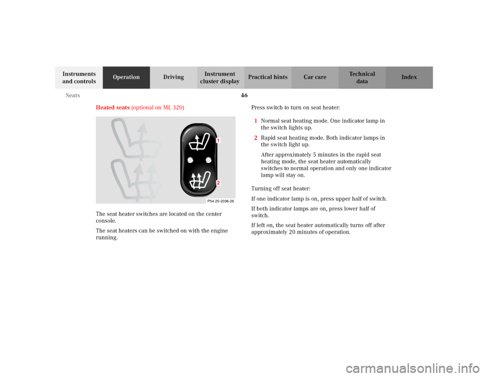
The seat heater switches are located on the center
console.
The seat heaters can be switched on with the engine
running.Press switch to turn on seat heater:
1Normal seat heating mode. One indicator lamp in
the switch lights up.
2Rapid seat heating mode. Both indicator lamps in
the switch light up.
After approximately 5 minutes in the rapid seat
heating mode, the seat heater automatically
switches to normal operation and only one indicator
lamp will stay on.
Turning off seat heater:
If one indicator lamp is on, press upper half of switch.
If both indicator lamps are on, press lower half of
switch.
If left on, the seat heater automatically turns off after
approximately 20 minutes of operation.
P54.25-2036-26
12
Page 52 of 342
49 Restraint systems
Te ch n i c a l
data Instruments
and controlsOperationDrivingInstrument
cluster displayPractical hints Car care Index Note:
For cleaning and care of the seat belts, see page 302.
Seat belt nonusage warning system
After starting the engine, a warning sounds and the seat
belt warning lamp< remains illuminated for
approximately 6 seconds if the driver’s seat belt is not
fastened.
Wa r n i n g !
Never ride in a moving vehicle with the backrest
reclined. Sitting in an excessively reclined position
can be dangerous. You could slide under the seat
belt in a collision. If you slide under it, the belt
would apply force at the abdomen or neck. That
could cause serious or even fatal injuries. The
backrest and seat belt provide the best restraint
when the wearer is in an upright position and the
belt is properly positioned on the body.
Wa r n i n g !
Failure to wear and properly fasten and position
your seat belt greatly increases your risk of
injuries and their likely severity in an accident.
You and your passengers should always wear seat
belts.If you are ever in an accident, your injuries can be
considerably more severe without your seat belt
properly buckled. Without your seat belt buckled,
you are much more likely to hit the interior of the
vehicle or be ejected from it. You can be seriously
injured or killed.In the same crash, the possibility for injury or
death is lessened if you are wearing your seat belt.Wa r n i n g !
Never let more people ride in the vehicle than there
are seat belts available. Be sure everyone riding in
the vehicle is correctly restrained with a separate
seat belt.
Page 77 of 342
74 Adjustable steering wheel
Te ch n i c a l
data Instruments
and controlsOperationDrivingInstrument
cluster displayPractical hints Car care Index
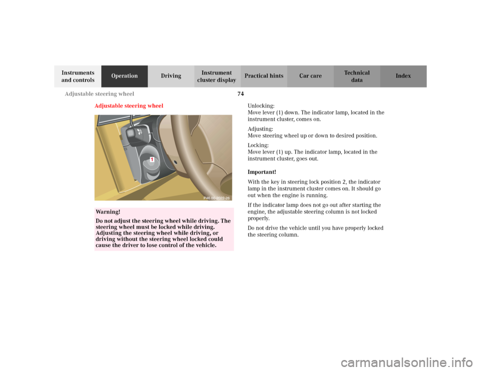
Adjustable steering wheelUnlocking:
Move lever (1) down. The indicator lamp, located in the
instrument cluster, comes on.
Adjusting:
Move steering wheel up or down to desired position.
Locking:
Move lever (1) up. The indicator lamp, located in the
instrument cluster, goes out.
Important!
With the key in steering lock position 2, the indicator
lamp in the instrument cluster comes on. It should go
out when the engine is running.
If the indicator lamp does not go out after starting the
engine, the adjustable steering column is not locked
properly.
Do not drive the vehicle until you have properly locked
the steering column.
Wa r n i n g !
Do not adjust the steering wheel while driving. The
steering wheel must be locked while driving.
Adjusting the steering wheel while driving, or
driving without the steering wheel locked could
cause the driver to lose control of the vehicle.
Page 86 of 342
83 Instrument cluster
Te ch n i c a l
data Instruments
and controlsOperationDrivingInstrument
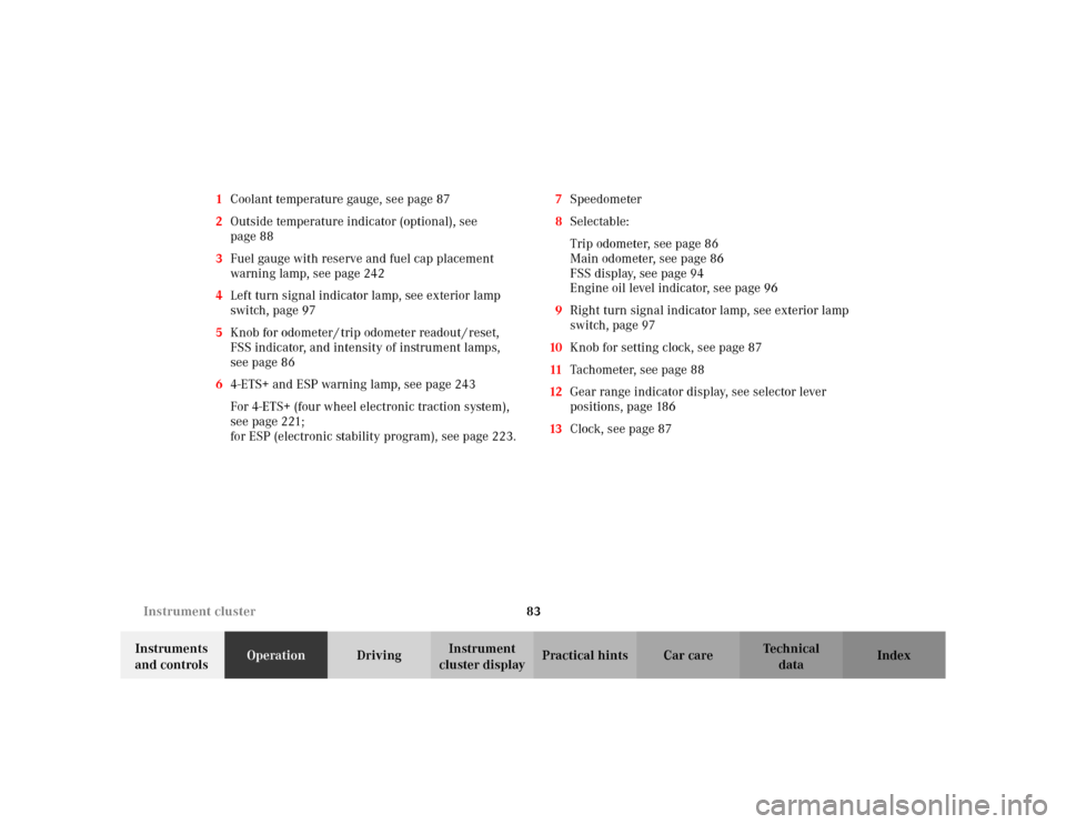
cluster displayPractical hints Car care Index 1Coolant temperature gauge, see page 87
2Outside temperature indicator (optional), see
page 88
3Fuel gauge with reserve and fuel cap placement
warning lamp, see page 242
4Left turn signal indicator lamp, see exterior lamp
switch, page 97
5Knob for odometer / trip odometer readout / reset,
FSS indicator, and intensity of instrument lamps,
see page 86
64-ETS+ and ESP warning lamp, see page 243
For 4-ETS+ (four wheel electronic traction system),
seepage221;
for ESP (electronic stability program), see page 223.7Speedometer
8Selectable:
Trip odometer, see page 86
Main odometer, see page 86
FSS display, see page 94
Engine oil level indicator, see page 96
9Right turn signal indicator lamp, see exterior lamp
switch, page 97
10Knob for setting clock, see page 87
11Tachometer, see page 88
12Gear range indicator display, see selector lever
positions, page 186
13Clock, see page 87
Page 87 of 342
84 Instrument cluster
Te ch n i c a l
data Instruments
and controlsOperationDrivingInstrument
cluster displayPractical hints Car care Index
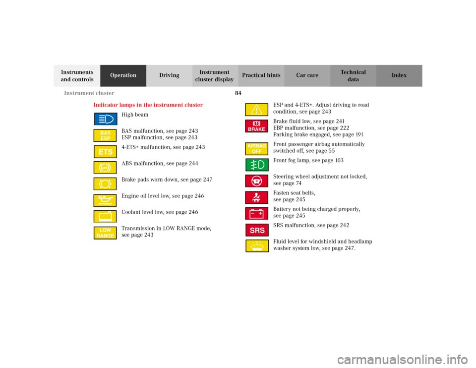
Indicator lamps in the instrument cluster
High beam
BAS malfunction, see page 243
ESP malfunction, see page 243
4-ETS+ malfunction, see page 243
ABS malfunction, see page 244
Brake pads worn down, see page 247
Engine oil level low, see page 246
Coolant level low, see page 246
Transmission in LOW RANGE mode,
see page 243ESP and 4-ETS+. Adjust driving to road
condition, see page 243
Brake fluid low, see page 241
EBP malfunction, see page 222
Parking brake engaged, see page 191
Front passenger airbag automatically
switched off, see page 55
Front fog lamp, see page 103
Steering wheel adjustment not locked,
see page 74
Fasten seat belts,
see page 245
Battery not being charged properly,
see page 245
SRS malfunction, see page 242
Fluid level for windshield and headlamp
washer system low, see page 247.
BAS
ESPABSLOW
RANGE
BRAKESRS
Page 88 of 342
85 Instrument cluster
Te ch n i c a l
data Instruments
and controlsOperationDrivingInstrument
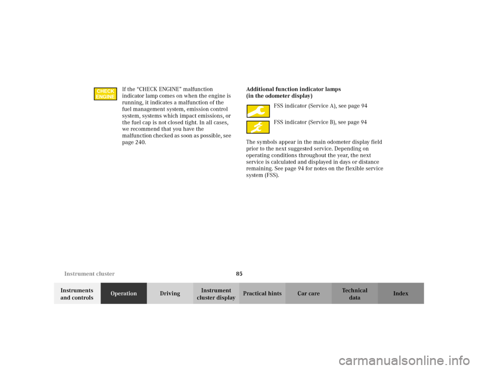
cluster displayPractical hints Car care Index If the “CHECK ENGINE” malfunction
indicator lamp comes on when the engine is
running, it indicates a malfunction of the
fuel management system, emission control
system, systems which impact emissions, or
the fuel cap is not closed tight. In all cases,
we recommend that you have the
malfunction checked as soon as possible, see
page 240.Additional function indicator lamps
(in the odometer display)
FSS indicator (Service A), see page 94
FSS indicator (Service B), see page 94
The symbols appear in the main odometer display field
prior to the next suggested service. Depending on
operating conditions throughout the year, the next
service is calculated and displayed in days or distance
remaining. See page 94 for notes on the flexible service
system (FSS).
CHECK
ENGINE
Page 90 of 342
87 Instrument cluster
Te ch n i c a l
data Instruments
and controlsOperationDrivingInstrument
cluster displayPractical hints Car care Index Clock (13)
Adjusting clock (instrument cluster activated):
Minute: Pull out knob (2) and turn it to the right.
Hour: Pull out knob (2) and turn it to the left.
Coolant temperature gauge (1)
During severe operating conditions and stop-and-go city
traffic, the coolant temperature may rise close to the red
marking.
The engine should not be operated with the coolant
temperature in the red zone. Doing so may cause
serious engine damage which is not covered by the
Mercedes-Benz Limited Warranty.
Wa r n i n g !
• Driving when your engine is badly overheated
can cause some fluids which may have leaked
into the engine compartment to catch fire. You
could be seriously burned.• Steam from an overheated engine can cause
serious burns and can occur just by opening
the engine hood. Stay away from the engine if
you see or hear steam coming from it.Turn off the engine, get out of the vehicle and do
not stand near the vehicle until it cools down.
Page 91 of 342
88 Instrument cluster
Te ch n i c a l
data Instruments
and controlsOperationDrivingInstrument
cluster displayPractical hints Car care Index
Outside temperature indicator (2)
The temperature sensor is located in the front bumper
area. Due to its location, the sensor can be affected by
road or engine heat during idling or slow driving. This
means that the accuracy of the displayed temperature
can only be verified by comparison to a thermometer
placed next to the sensor, not by comparison to external
displays (e.g. bank signs etc.).
Adaptation to ambient temperature takes place in steps
and depends on the prevailing driving conditions (stop-
and-go or moderate, constant driving) and amount of
temperature change.Tachometer (11)
The tachometer displays the present engine speed in
revolutions per minute (RPM).
To help protect the engine, the fuel supply is interrupted
if the engine is operated above its specified limit.
Wa r n i n g !
The outside temperature indicator is not designed
to serve as an Ice-Warning Device and is therefore
unsuitable for that purpose. Indicated
temperatures just above the freezing point do not
guarantee that the road surface is free of ice.