engine coolant MERCEDES-BENZ ML350 1997 Complete Owners Manual
[x] Cancel search | Manufacturer: MERCEDES-BENZ, Model Year: 1997, Model line: ML350, Model: MERCEDES-BENZ ML350 1997Pages: 4133, PDF Size: 88.89 MB
Page 2105 of 4133

GF54.30-P-2002A
Display instruments, location / task / function
24.10.96
MODEL
129, 140 as of 1.6.96,
163, 168, 170,
202 as of 1.8.96,
208 up to 31.7.99,
210 as of 1.6.96 up to 30.6.99
Display
Type of data transmission
D
Outside temperature indicator (A1p4)
D
Fuel level gauge (A1p2)
D
Engine oil pressure gauge (A1p3), only
model 129 and model 140
D
Low windshield washer fluid level
indicator lamp (A1e13), model 163 as of
01.09.01
Direct lines
GF54.30-P-3004A
D
Total mileage odometer (A1h4)
D
Electronic speedometer (A1p8)
D
Tachometer (A1p5)
D
Coolant temperature gauge (A1p1)
D
Active service system (ASSYST)
D
Gear indicator (A1p12), only model 168
CAN data lines
GF54.30-P-3005A
D
Electronic clock
Internal
GF54.30-P-3011A
Copyright DaimlerChrysler AG 04.06.2006 CD-Ausgabe G/10/04 . This WIS print-out will not be recorde
d by Modification services.
Page 1
Page 2107 of 4133

GF54.30-P-3028GH
Displaying coolant level, function
28.6.99
MODEL
163 as of 1.3.99
Function prerequisite
Engine: ON
Function
If the coolant level drops below the minimum mark the low ECL
indicator lamp (A1p11) is illuminated.
To record the coolant level the instrument cluster (A1) is connected
direct to the
coolant level indicator electronic switch (S41)
via two
cables. The
coolant level indicator electronic switch (S41)
consists of two electrodes.
D
If the
level is correct
both electrodes are immersed in the
coolant. The coolant serves as a dielectric between the
electrodes.
D
If the coolant level is below the minimum mark the electrodes of
the sensor are no longer immersed in the coolant. There is only
air between the electrodes as a dielectric. Evaluation
The instrument cluster (A1) sends test pulses to the sensor for
a period of one millisecond. These pulses are deformed
differently depending on the dielectric (air or coolant).
The instrument cluster (A1) evaluates the pulse shape and, if
the coolant level is below the minimum (electrodes are
completely in air), actuates the low ECL indicator lamp (A1p11)
after a delay of
approx. 60 seconds
.
The delay serves to prevent the indicator lamp flickering due to
the coolant moving from side to side on corners or off-road.
Diagnosis
Diagnosis is carried out, as described in the Diagnosis Manual, via
the simulation of the
coolant level indicator electronic switch (S41)
by a resistance.
Coolant level switch,
location/task/design/function
GF54.30-P-4103GH
Copyright DaimlerChrysler AG 04.06.2006 CD-Ausgabe G/10/04 . This WIS print-out will not be recorde
d by Modification services.
Page 1
Page 2143 of 4133
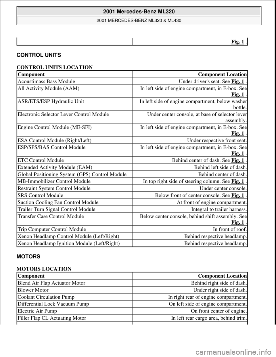
CONTROL UNITS
CONTROL UNITS LOCATION
MOTORS
MOTORS LOCATION
Fig. 1 .
ComponentComponent Location
Acoustimass Bass ModuleUnder driver's seat. See Fig. 1 .
All Activity Module (AAM)In left side of engine compartment, in E-box. See
Fig. 1
.
ASR/ETS/ESP Hydraulic UnitIn left side of engine compartment, below washer
bottle.
Electronic Selector Lever Control ModuleUnder center console, at base of selector lever
assembly.
Engine Control Module (ME-SFI)In left side of engine compartment, in E-box. See
Fig. 1
.
ESA Control Module (Right/Left)Under respective front seat.
ESP/SPS/BAS Control ModuleIn left side of engine compartment, in E-box. See
Fig. 1
.
ETC Control ModuleBehind center of dash. See Fig. 1 .
Extended Activity Module (EAM)Behind left side of dash.
Global Positioning System (GPS) Control ModuleBehind center of dash.
MB-Immobilizer Control ModuleIn top right side of steering column. See Fig. 1 .
Restraint System Control ModuleUnder center console.
SRS Control ModuleBelow front of center console. See Fig. 1 .
Suction Cooling Fan Control ModuleAt front of engine compartment.
Trailer Turn Signal Control ModuleIntegral to trailer harness.
Transfer Case Control ModuleBelow center console, behind shift assembly. See
Fig. 1
.
Trip Computer Control ModuleIn front of roof.
Xenon Headlamp Control Module (Left/Right)Behind respective headlamp.
Xenon Headlamp Ignition Module (Left/Right)Behind respective headlamp.
ComponentComponent Location
Blend Air Flap Actuator MotorBehind right side of dash.
Blower MotorUnder right side of dash.
Coolant Circulation PumpIn right rear of engine compartment.
Differential Lock Vacuum PumpOn left side of engine compartment.
Electric Air PumpOn front center of engine.
Filler Flap CL Actuating MotorIn left rear cargo area, behind trim.
2001 Mercedes-Benz ML320
2001 MERCEDES-BENZ ML320 & ML430
me
Saturday, October 02, 2010 3:21:17 PMPage 3 © 2006 Mitchell Repair Information Company, LLC.
Page 2171 of 4133
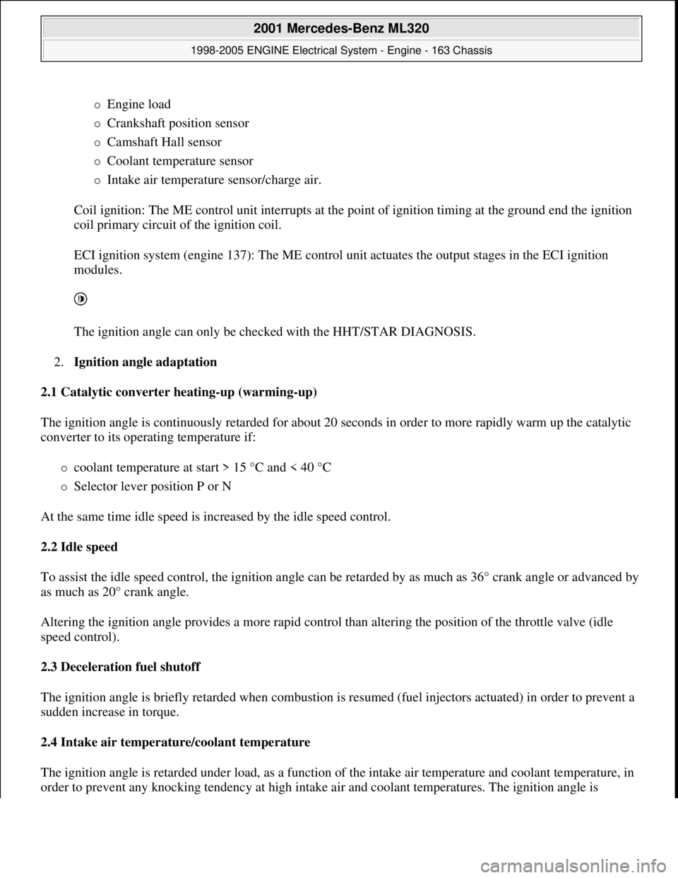
Engine load
Crankshaft position sensor
Camshaft Hall sensor
Coolant temperature sensor
Intake air temperature sensor/charge air.
Coil ignition: The ME control unit interrupts at the point of ignition timing at the ground end the ignition
coil primary circuit of the ignition coil.
ECI ignition system (engine 137): The ME control unit actuates the output stages in the ECI ignition
modules.
The ignition angle can only be checked with the HHT/STAR DIAGNOSIS.
2.Ignition angle adaptation
2.1 Catalytic converter heating-up (warming-up)
The ignition angle is continuously retarded for about 20 seconds in order to more rapidly warm up the catalytic
converter to its operating temperature if:
coolant temperature at start > 15 °C and < 40 °C
Selector lever position P or N
At the same time idle speed is increased by the idle speed control.
2.2 Idle speed
To assist the idle speed control, the ignition angle can be retarded by as much as 36° crank angle or advanced by
as much as 20° crank angle.
Altering the ignition angle provides a more rapid control than altering the position of the throttle valve (idle
speed control).
2.3 Deceleration fuel shutoff
The ignition angle is briefly retarded when combustion is resumed (fuel injectors actuated) in order to prevent a
sudden increase in torque.
2.4 Intake air temperature/coolant temperature
The ignition angle is retarded under load, as a function of the intake air temperature and coolant temperature, in
order to prevent an
y knocking tendency at high intake air and coolant temperatures. The ignition angle is
2001 Mercedes-Benz ML320
1998-2005 ENGINE Electrical System - Engine - 163 Chassis
me
Saturday, October 02, 2010 3:18:54 PMPage 17 © 2006 Mitchell Repair Information Company, LLC.
Page 2172 of 4133
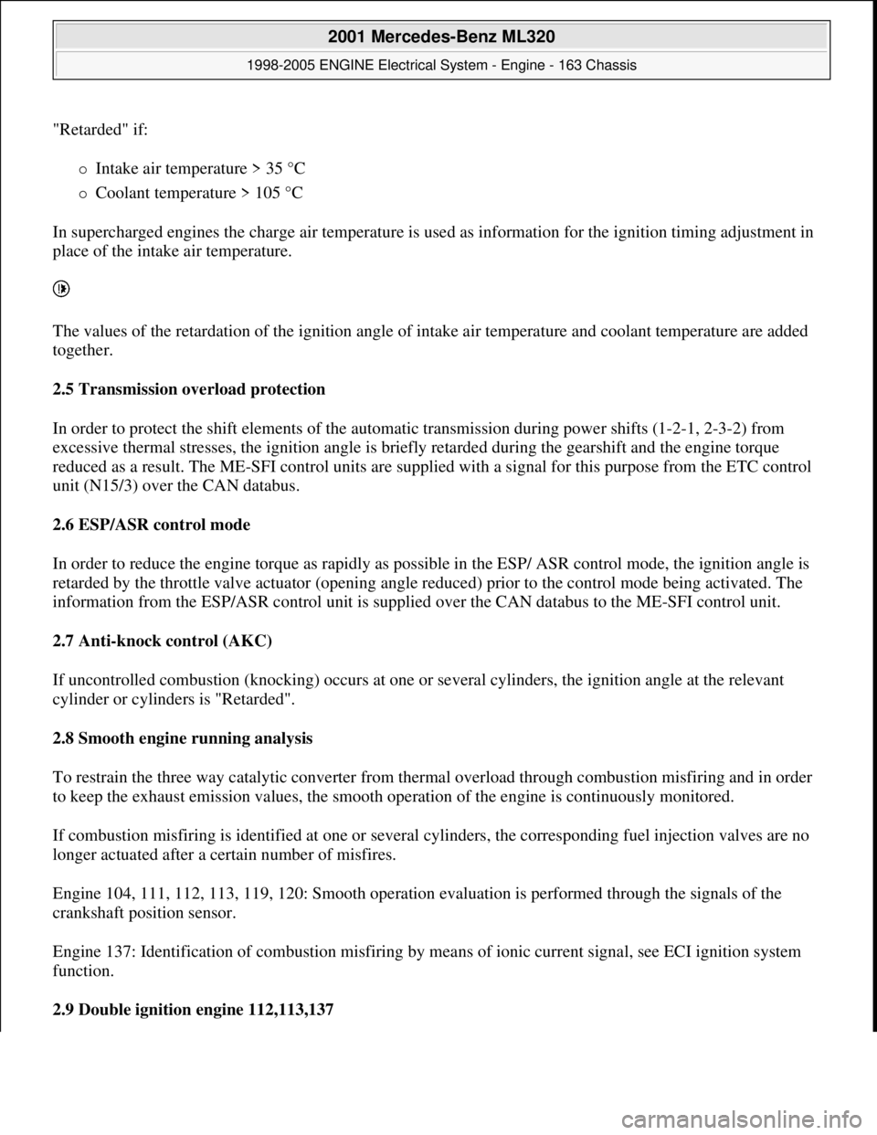
"Retarded" if:
Intake air temperature > 35 °C
Coolant temperature > 105 °C
In supercharged engines the charge air temperature is used as information for the ignition timing adjustment in
place of the intake air temperature.
The values of the retardation of the ignition angle of intake air temperature and coolant temperature are added
together.
2.5 Transmission overload protection
In order to protect the shift elements of the automatic transmission during power shifts (1-2-1, 2-3-2) from
excessive thermal stresses, the ignition angle is briefly retarded during the gearshift and the engine torque
reduced as a result. The ME-SFI control units are supplied with a signal for this purpose from the ETC control
unit (N15/3) over the CAN databus.
2.6 ESP/ASR control mode
In order to reduce the engine torque as rapidly as possible in the ESP/ ASR control mode, the ignition angle is
retarded by the throttle valve actuator (opening angle reduced) prior to the control mode being activated. The
information from the ESP/ASR control unit is supplied over the CAN databus to the ME-SFI control unit.
2.7 Anti-knock control (AKC)
If uncontrolled combustion (knocking) occurs at one or several cylinders, the ignition angle at the relevant
cylinder or cylinders is "Retarded".
2.8 Smooth engine running analysis
To restrain the three way catalytic converter from thermal overload through combustion misfiring and in order
to keep the exhaust emission values, the smooth operation of the engine is continuously monitored.
If combustion misfiring is identified at one or several cylinders, the corresponding fuel injection valves are no
longer actuated after a certain number of misfires.
Engine 104, 111, 112, 113, 119, 120: Smooth operation evaluation is performed through the signals of the
crankshaft position sensor.
Engine 137: Identification of combustion misfiring by means of ionic current signal, see ECI ignition system
function.
2.9 Double ignition engine 112,113,137
2001 Mercedes-Benz ML320
1998-2005 ENGINE Electrical System - Engine - 163 Chassis
me
Saturday, October 02, 2010 3:18:54 PMPage 18 © 2006 Mitchell Repair Information Company, LLC.
Page 2173 of 4133
Two spark plugs for each cylinder are beneficial because of the arrangement of the valves for achieving optimal
emission levels and smooth engine running.
Each spark plug is actuated separately by the ME-SFI control unit through its own ignition coil. On engine 112,
113 both ignition coils of a cylinder are combined to form a dual ignition coil.
In the lower part load range up to approx. 2000 rpm both ignition sparks of a cylinder are triggered
simultaneously. At moderate and high engine loads, the ignition sparks are triggered offset by as much as 10°
crank angle. In this case, the sequence of actuation is constantly varied in order to achieve a uniform wear of
both spark plugs and to avoid deposits on only one side of the combustion chamber.
For troubleshooting in the dual ignition system, it is possible to switch off one ignition circuit each with HHT or
STAR DIAGNOSIS.
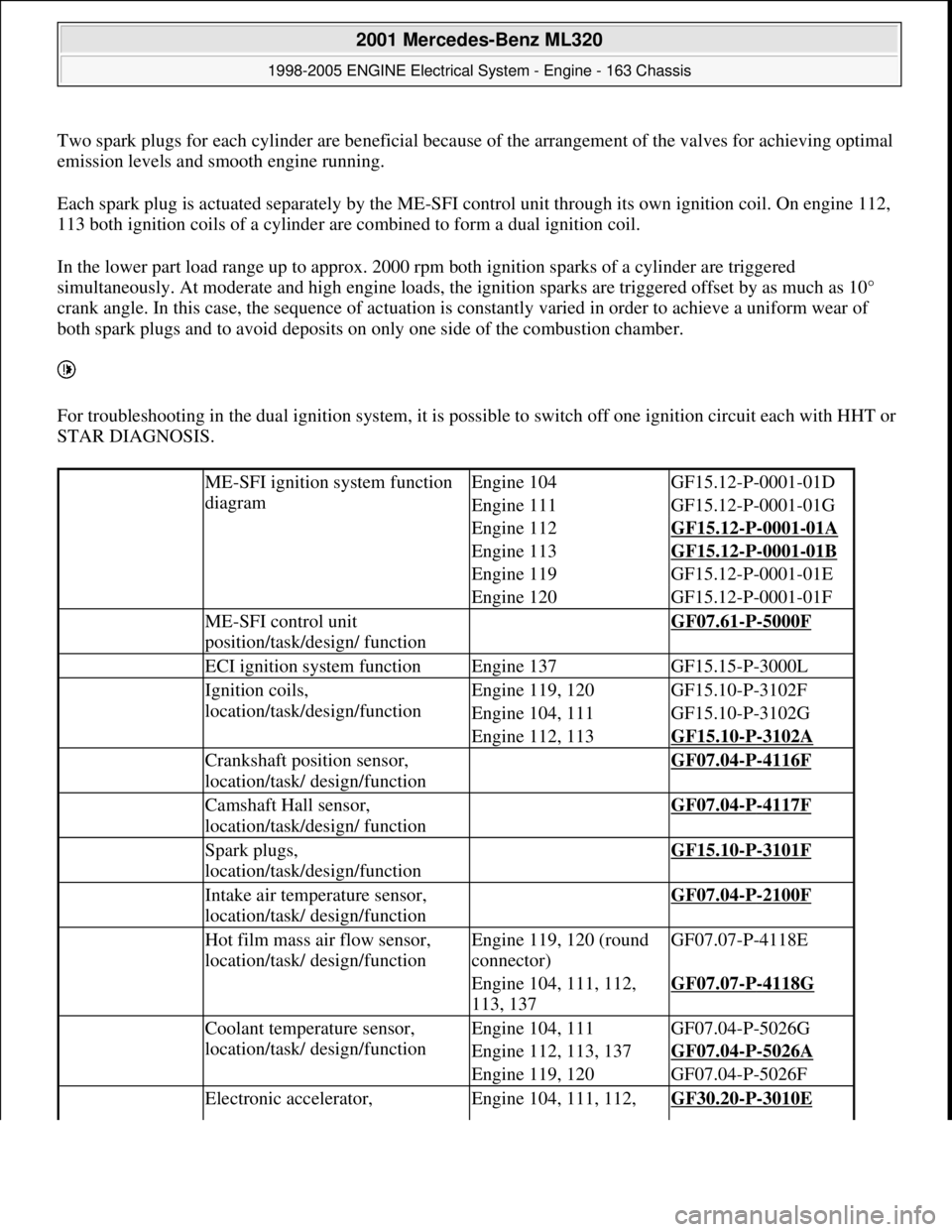
ME-SFI ignition system function
diagramEngine 104GF15.12-P-0001-01D
Engine 111GF15.12-P-0001-01G
Engine 112GF15.12-P-0001-01A
Engine 113GF15.12-P-0001-01B
Engine 119GF15.12-P-0001-01E
Engine 120GF15.12-P-0001-01F
ME-SFI control unit
position/task/design/ function GF07.61-P-5000F
ECI ignition system functionEngine 137GF15.15-P-3000L
Ignition coils,
location/task/design/functionEngine 119, 120GF15.10-P-3102F
Engine 104, 111GF15.10-P-3102G
Engine 112, 113GF15.10-P-3102A
Crankshaft position sensor,
location/task/ design/function GF07.04-P-4116F
Camshaft Hall sensor,
location/task/design/ function GF07.04-P-4117F
Spark plugs,
location/task/design/function GF15.10-P-3101F
Intake air temperature sensor,
location/task/ design/function GF07.04-P-2100F
Hot film mass air flow sensor,
location/task/ design/functionEngine 119, 120 (round
connector)GF07.07-P-4118E
Engine 104, 111, 112,
113, 137GF07.07-P-4118G
Coolant temperature sensor,
location/task/ design/functionEngine 104, 111GF07.04-P-5026G
Engine 112, 113, 137GF07.04-P-5026A
Engine 119, 120GF07.04-P-5026F
Electronic accelerator, Engine 104, 111, 112, GF30.20-P-3010E
2001 Mercedes-Benz ML320
1998-2005 ENGINE Electrical System - Engine - 163 Chassis
me
Saturday, October 02, 2010 3:18:54 PMPage 19 © 2006 Mitchell Repair Information Company, LLC.
Page 2177 of 4133
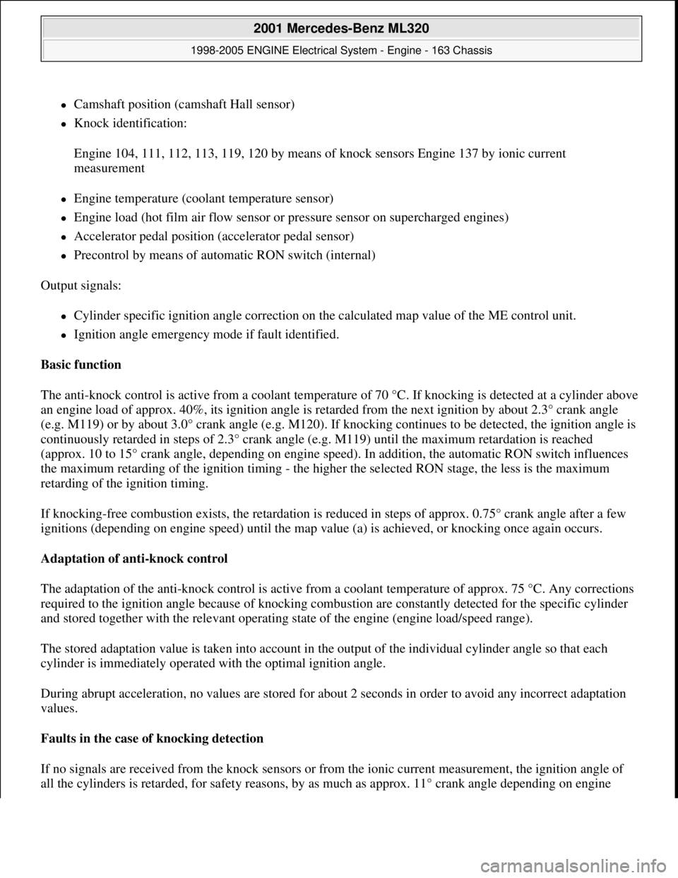
Camshaft position (camshaft Hall sensor)
Knock identification:
Engine 104, 111, 112, 113, 119, 120 by means of knock sensors Engine 137 by ionic current
measurement
Engine temperature (coolant temperature sensor)
Engine load (hot film air flow sensor or pressure sensor on supercharged engines)
Accelerator pedal position (accelerator pedal sensor)
Precontrol by means of automatic RON switch (internal)
Output signals:
Cylinder specific ignition angle correction on the calculated map value of the ME control unit.
Ignition angle emergency mode if fault identified.
Basic function
The anti-knock control is active from a coolant temperature of 70 °C. If knocking is detected at a cylinder above
an engine load of approx. 40%, its ignition angle is retarded from the next ignition by about 2.3° crank angle
(e.g. M119) or by about 3.0° crank angle (e.g. M120). If knocking continues to be detected, the ignition angle is
continuously retarded in steps of 2.3° crank angle (e.g. M119) until the maximum retardation is reached
(approx. 10 to 15° crank angle, depending on engine speed). In addition, the automatic RON switch influences
the maximum retarding of the ignition timing - the higher the selected RON stage, the less is the maximum
retarding of the ignition timing.
If knocking-free combustion exists, the retardation is reduced in steps of approx. 0.75° crank angle after a few
ignitions (depending on engine speed) until the map value (a) is achieved, or knocking once again occurs.
Adaptation of anti-knock control
The adaptation of the anti-knock control is active from a coolant temperature of approx. 75 °C. Any corrections
required to the ignition angle because of knocking combustion are constantly detected for the specific cylinder
and stored together with the relevant operating state of the engine (engine load/speed range).
The stored adaptation value is taken into account in the output of the individual cylinder angle so that each
cylinder is immediately operated with the optimal ignition angle.
During abrupt acceleration, no values are stored for about 2 seconds in order to avoid any incorrect adaptation
values.
Faults in the case of knocking detection
If no signals are received from the knock sensors or from the ionic current measurement, the ignition angle of
all the c
ylinders is retarded, for safety reasons, by as much as approx. 11° crank angle depending on engine
2001 Mercedes-Benz ML320
1998-2005 ENGINE Electrical System - Engine - 163 Chassis
me
Saturday, October 02, 2010 3:18:54 PMPage 23 © 2006 Mitchell Repair Information Company, LLC.
Page 2178 of 4133
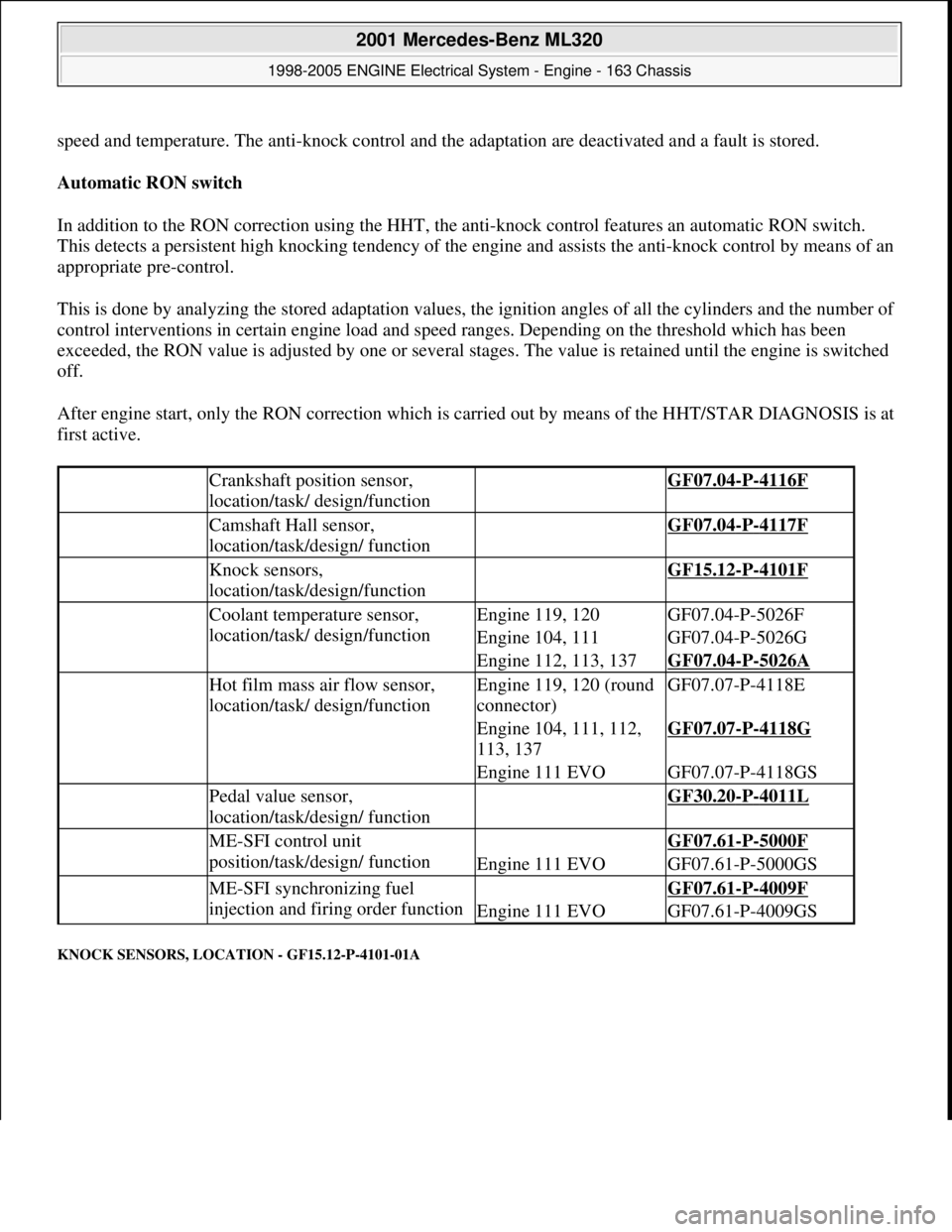
speed and temperature. The anti-knock control and the adaptation are deactivated and a fault is stored.
Automatic RON switch
In addition to the RON correction using the HHT, the anti-knock control features an automatic RON switch.
This detects a persistent high knocking tendency of the engine and assists the anti-knock control by means of an
appropriate pre-control.
This is done by analyzing the stored adaptation values, the ignition angles of all the cylinders and the number of
control interventions in certain engine load and speed ranges. Depending on the threshold which has been
exceeded, the RON value is adjusted by one or several stages. The value is retained until the engine is switched
off.
After engine start, only the RON correction which is carried out by means of the HHT/STAR DIAGNOSIS is at
first active.
KNOCK SENSORS, LOCATION - GF15.12-P-4101-01A
Crankshaft position sensor,
location/task/ design/function GF07.04-P-4116F
Camshaft Hall sensor,
location/task/design/ function GF07.04-P-4117F
Knock sensors,
location/task/design/function GF15.12-P-4101F
Coolant temperature sensor,
location/task/ design/functionEngine 119, 120GF07.04-P-5026F
Engine 104, 111GF07.04-P-5026G
Engine 112, 113, 137GF07.04-P-5026A
Hot film mass air flow sensor,
location/task/ design/functionEngine 119, 120 (round
connector)GF07.07-P-4118E
Engine 104, 111, 112,
113, 137GF07.07-P-4118G
Engine 111 EVOGF07.07-P-4118GS
Pedal value sensor,
location/task/design/ function GF30.20-P-4011L
ME-SFI control unit
position/task/design/ function GF07.61-P-5000F
Engine 111 EVOGF07.61-P-5000GS
ME-SFI synchronizing fuel
injection and firing order function GF07.61-P-4009F
Engine 111 EVOGF07.61-P-4009GS
2001 Mercedes-Benz ML320
1998-2005 ENGINE Electrical System - Engine - 163 Chassis
me
Saturday, October 02, 2010 3:18:54 PMPage 24 © 2006 Mitchell Repair Information Company, LLC.
Page 2356 of 4133
1998-2005 ENGINE
Complete engine - 163 Chassis
GENERAL INFORMATION
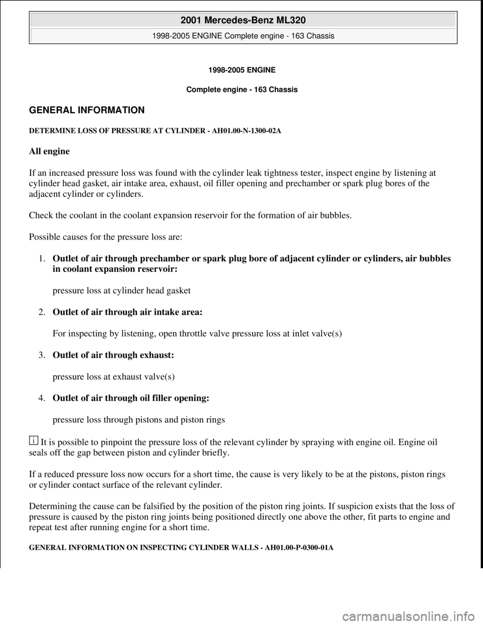
DETERMINE LOSS OF PR ESSURE AT CYLINDER - AH01.00-N-1300-02A
All engine
If an increased pressure loss was found with the cylinde r leak tightness tester, inspect engine by listening at
cylinder head gasket, air intake area, exhaust, oil fi ller opening and prechamber or spark plug bores of the
adjacent cylinder or cylinders.
Check the coolant in the coolant expansion reservoir for the formation of air bubbles.
Possible causes for the pressure loss are: 1. Outlet of air through prechamber or spark plug bo re of adjacent cylinder or cylinders, air bubbles
in coolant expansion reservoir:
pressure loss at cylinder head gasket
2. Outlet of air through air intake area:
For inspecting by listening, open throttle valve pressure loss at inlet valve(s)
3. Outlet of air through exhaust:
pressure loss at exhaust valve(s)
4. Outlet of air through oil filler opening:
pressure loss through pistons and piston rings
It is possible to pinpoint the pressure loss of the rele vant cylinder by spraying with engine oil. Engine oil
seals off the gap between piston and cylinder briefly.
If a reduced pressure loss now occurs for a short time, th e cause is very likely to be at the pistons, piston rings
or cylinder contact surface of the relevant cylinder.
Determining the cause can be falsified by the position of th e piston ring joints. If suspicion exists that the loss o
f
pressure is caused by the piston ring joints being positioned directly one above the other, fit parts to engine and
repeat test after running engine for a short time.
GENERAL INFORMATION ON INSPECTING CYLINDER WALLS - AH01.00-P-0300-01A
2001 Mercedes-Benz ML320
1998-2005 ENGINE Complete engine - 163 Chassis
2001 Mercedes-Benz ML320
1998-2005 ENGINE Complete engine - 163 Chassis
me
Saturday, October 02, 2010 3:17:55 PMPage 1 © 2006 Mitchell Repair Information Company, LLC.
me
Saturday, October 02, 2010 3:18:01 PMPage 1 © 2006 Mitchell Repair Information Company, LLC.
Page 2379 of 4133
The sealing compound must only be applied to the speci fied surfaces in the form of a bead of 2.0 mm ± 0.5
mm in diameter.
The sealing compound must be processe d within 10 min. The sealing compound bead must not be spread. Only
the sealing compound listed in the s ection Repair products may be used.
TROUBLE DIAGNOSIS
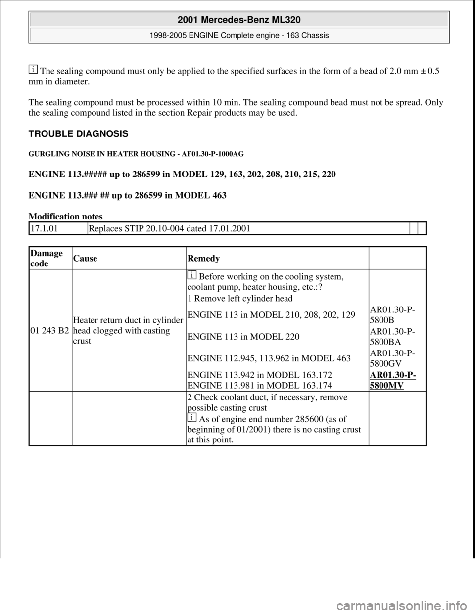
GURGLING NOISE IN HEA TER HOUSING - AF01.30-P-1000AG
ENGINE 113.##### up to 286599 in MODEL 129, 163, 202, 208, 210, 215, 220
ENGINE 113.### ## up to 286599 in MODEL 463
Modification notes
17.1.01Replaces STIP 20.10-004 dated 17.01.2001
Damage
codeCauseRemedy
01 243 B2
Heater return duct in cylinder
head clogged with casting
crust
Before working on the cooling system,
coolant pump, heater housing, etc.:?
1 Remove left cylinder head
ENGINE 113 in MODEL 210, 208, 202, 129AR01.30-P-
5800B
ENGINE 113 in MODEL 220AR01.30-P-
5800BA
ENGINE 112.945, 113.962 in MODEL 463AR01.30-P-
5800GV
ENGINE 113.942 in MODEL 163.172
ENGINE 113.981 in MODEL 163.174AR01.30-P-
5800MV
2 Check coolant duct, if necessary, remove
possible casting crust
As of engine end number 285600 (as of
beginning of 01/2001) there is no casting crust
at this point.
2001 Mercedes-Benz ML320
1998-2005 ENGINE Complete engine - 163 Chassis
me
Saturday, October 02, 2010 3:17:56 PMPage 23 © 2006 Mitchell Repair Information Company, LLC.