seats MERCEDES-BENZ ML350 1997 Complete Repair Manual
[x] Cancel search | Manufacturer: MERCEDES-BENZ, Model Year: 1997, Model line: ML350, Model: MERCEDES-BENZ ML350 1997Pages: 4133, PDF Size: 88.89 MB
Page 1494 of 4133
AR91.12-P-1010GI
Remove and install bench
21.3.00
MODELS
163.136 /154 /172 as of 1.9.99,
163.113 /128 /157 /174 /175
40 % bench seat
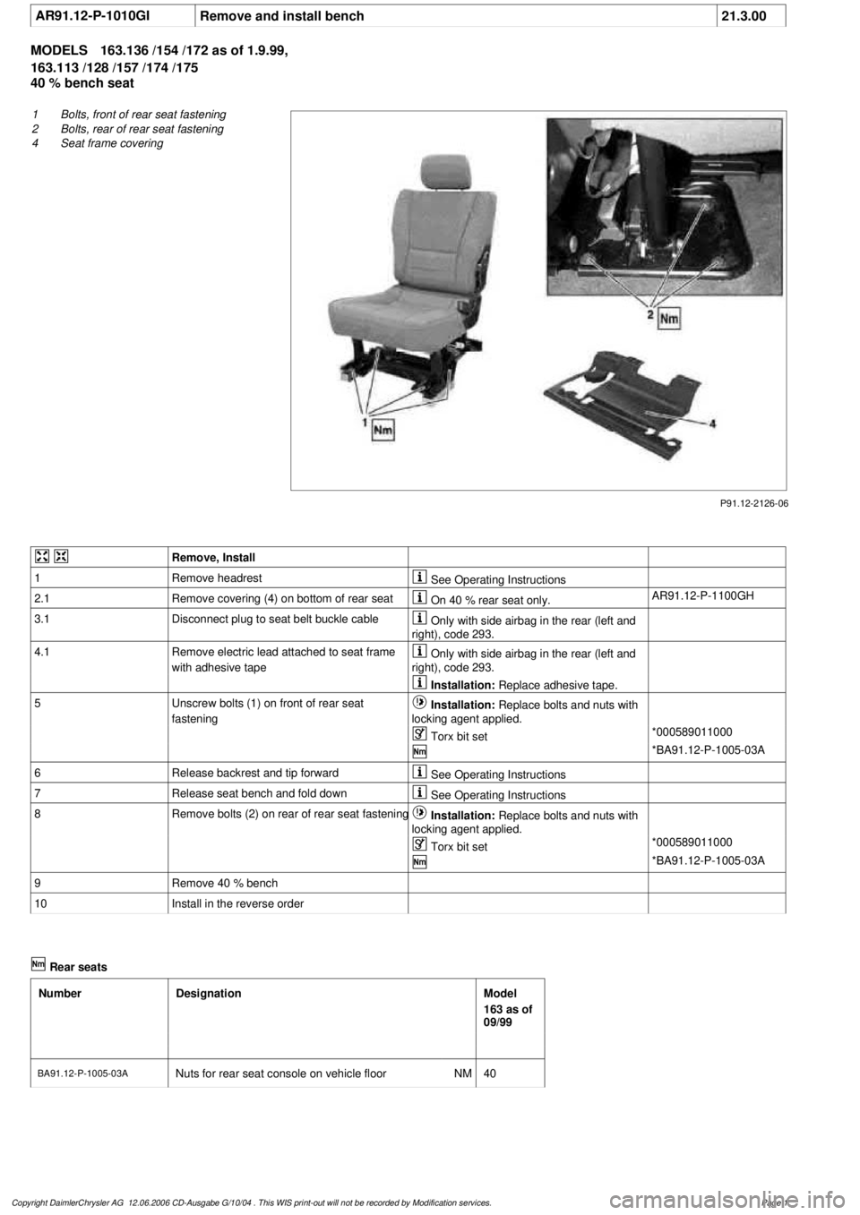
P91.12-2126-06
1
Bolts, front of rear seat fastening
2
Bolts, rear of rear seat fastening
4
Seat frame covering
Remove, Install
1
Remove headrest
See Operating Instructions
2.1
Remove covering (4) on bottom of rear seat
On 40 % rear seat only.
AR91.12-P-1100GH
3.1
Disconnect plug to seat belt buckle cable
Only with side airbag in the rear (left and
right), code 293.
4.1
Remove electric lead attached to seat frame
with adhesive tape
Only with side airbag in the rear (left and
right), code 293.
Installation:
Replace adhesive tape.
5
Unscrew bolts (1) on front of rear seat
fastening
Installation:
Replace bolts and nuts with
locking agent applied.
Torx bit set
*000589011000
*BA91.12-P-1005-03A
6
Release backrest and tip forward
See Operating Instructions
7
Release seat bench and fold down
See Operating Instructions
8
Remove bolts (2) on rear of rear seat fastening
Installation:
Replace bolts and nuts with
locking agent applied.
Torx bit set
*000589011000
*BA91.12-P-1005-03A
9
Remove 40 % bench
10
Install in the reverse order
Rear seats
Number
Designation
Model
163 as of
09/99
BA91.12-P-1005-03A
Nuts for rear seat console on vehicle floor
NM
40
Copyright DaimlerChrysler AG 12.06.2006 CD-Ausgabe G/10/04 . This WIS print-out will not be recorde
d by Modification services.
Page 1
Page 1791 of 4133
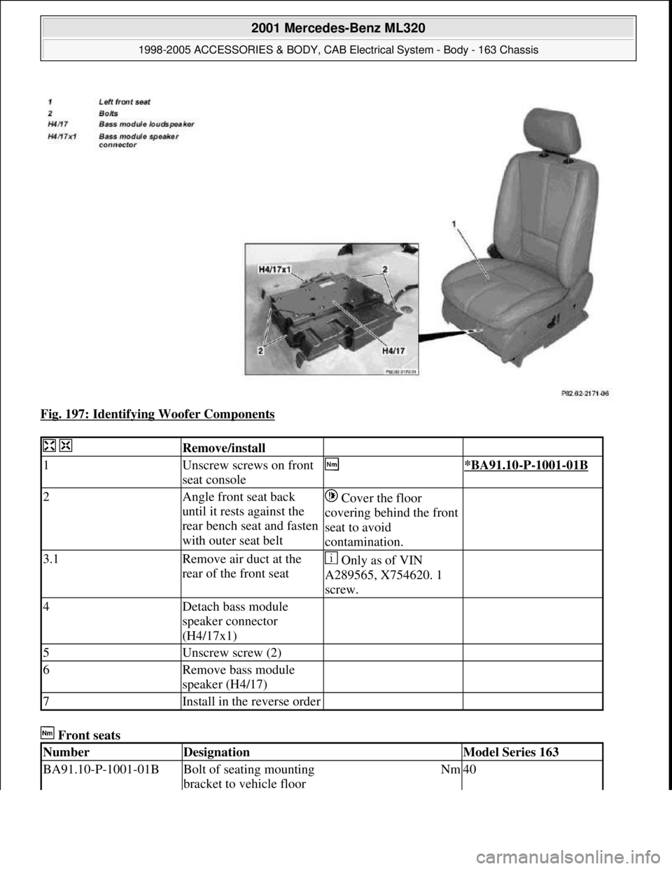
Fig. 197: Identifying Woofer Components
Front seats
Remove/install
1Unscrew screws on front
seat console *BA91.10-P-1001-01B
2Angle front seat back
until it rests against the
rear bench seat and fasten
with outer seat belt Cover the floor
covering behind the front
seat to avoid
contamination.
3.1Remove air duct at the
rear of the front seat Only as of VIN
A289565, X754620. 1
screw.
4Detach bass module
speaker connector
(H4/17x1)
5Unscrew screw (2)
6Remove bass module
speaker (H4/17)
7Install in the reverse order
NumberDesignationModel Series 163
BA91.10-P-1001-01BBolt of seating mounting
bracket to vehicle floorNm40
2001 Mercedes-Benz ML320
1998-2005 ACCESSORIES & BODY, CAB Electrical System - Body - 163 Chassis
me
Saturday, October 02, 2010 3:30:09 PMPage 296 © 2006 Mitchell Repair Information Company, LLC.
Page 1808 of 4133
Front seats
Seat belts/emergency tensioning retractors
FIBER OPTICAL CABLE (D2B) REPLACE COMPLETE (AFTER TESTING) - AR82.70-P-0005GJ
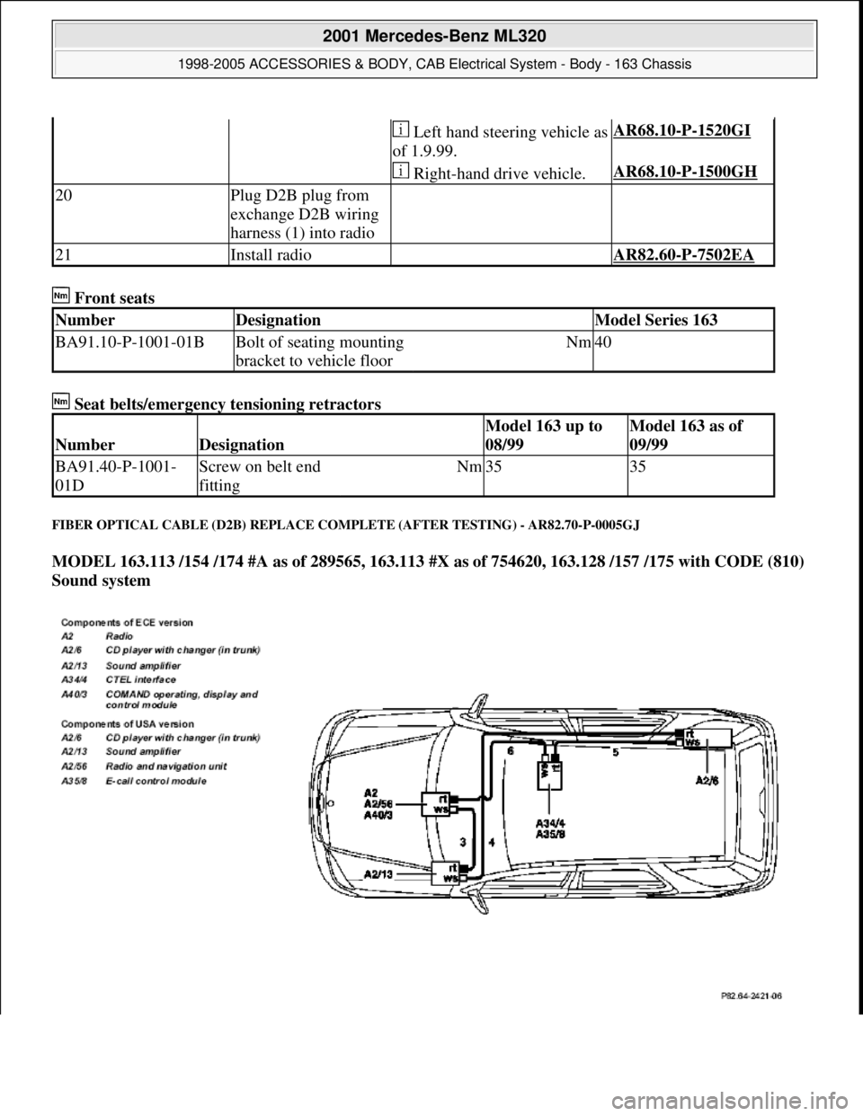
MODEL 163.113 /154 /174 #A as of 289565, 163.113 #X as of 754620, 163.128 /157 /175 with CODE (810)
Sound system
Left hand steering vehicle as
of 1.9.99.AR68.10-P-1520GI
Right-hand drive vehicle.AR68.10-P-1500GH
20Plug D2B plug from
exchange D2B wiring
harness (1) into radio
21Install radio AR82.60-P-7502EA
NumberDesignationModel Series 163
BA91.10-P-1001-01BBolt of seating mounting
bracket to vehicle floorNm40
NumberDesignation
Model 163 up to
08/99Model 163 as of
09/99
BA91.40-P-1001-
01DScrew on belt end
fittingNm3535
2001 Mercedes-Benz ML320
1998-2005 ACCESSORIES & BODY, CAB Electrical System - Body - 163 Chassis
me
Saturday, October 02, 2010 3:30:10 PMPage 313 © 2006 Mitchell Repair Information Company, LLC.
Page 1814 of 4133
![MERCEDES-BENZ ML350 1997 Complete Repair Manual Front seats
REPLACE FIBER OPTICAL CABLE (D2B) BETWEEN THE RADIO AND E-CALL CONTROL MODULE/CTEL [TEL]
INTERFACE (AFTER TESTING) - AR82.95-P-0015GH
MODEL 163.136 #A as of 051500, 163.136 #X as of 70 MERCEDES-BENZ ML350 1997 Complete Repair Manual Front seats
REPLACE FIBER OPTICAL CABLE (D2B) BETWEEN THE RADIO AND E-CALL CONTROL MODULE/CTEL [TEL]
INTERFACE (AFTER TESTING) - AR82.95-P-0015GH
MODEL 163.136 #A as of 051500, 163.136 #X as of 70](/img/4/57306/w960_57306-1813.png)
Front seats
REPLACE FIBER OPTICAL CABLE (D2B) BETWEEN THE RADIO AND E-CALL CONTROL MODULE/CTEL [TEL]
INTERFACE (AFTER TESTING) - AR82.95-P-0015GH
MODEL 163.136 #A as of 051500, 163.136 #X as of 708319, 163.154 #A as of 051500, 163.154 #X as of
708319, 163.172 #A as of 051500, 163.172 #X as of 708319, 163.113/128/157/174/175 with CODE (852)
CTEL preinstallation assembly at dome with CODE (854) MB portable cellular telephone
MODEL 163.154 /172 /174 #A as of 221506, 163.157/175 with CODE (349) E Call emergency call system
with CODE (494a) USA version
1Remove fuse f8 from fuse
and relay module
2Unscrew screws on front
seat console *BA91.10-P-1001-01B
3Angle front seat back
until it rests against the
rear bench seat and fasten
with outer seat belt Remove wiring
harness for E-call speaker
from E-call bracket.
Cover the floor covering
behind the front seat to
avoid contamination.
4Detach connector (2) and
antenna plug (4) from the
E-call control module
(A35/8)
5Detach conductive
coupling D2B (3) Do not kink or stretch
fiber optic cable. Press
protective caps on
conductive coupling and
device connection.AR82.95-P-0005-01A
6Unscrew screws (5)
7Remove E-call control
module (A35/8)
8Install in the reverse order
NumberDesignationModel Series 163
BA91.10-P-1001-01BBolt of seating mounting
bracket to vehicle floorNm40
2001 Mercedes-Benz ML320
1998-2005 ACCESSORIES & BODY, CAB Electrical System - Body - 163 Chassis
me
Saturday, October 02, 2010 3:30:10 PMPage 319 © 2006 Mitchell Repair Information Company, LLC.
Page 1817 of 4133
Front seats
Seat belts/emergency tensioning retractors
MAINTENANCE
CHECK SETTING OF HIGH BEAM - AP82.10-P-8260-02A
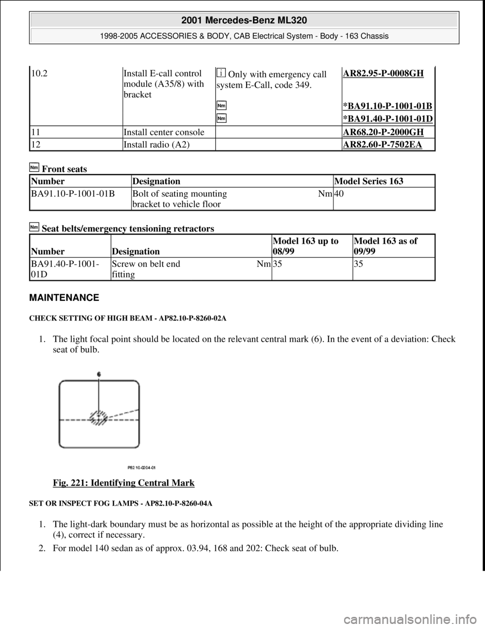
1. The light focal point should be located on the relevant central mark (6). In the event of a deviation: Check
seat of bulb.
Fig. 221: Identifying Central Mark
SET OR INSPECT FOG LAMPS - AP82.10-P-8260-04A
1. The light-dark boundary must be as horizontal as possible at the height of the appropriate dividing line
(4), correct if necessary.
2. For model 140 sedan as of approx. 03.94, 168 and 202: Check seat of bulb.
10.2Install E-call control
module (A35/8) with
bracket Only with emergency call
system E-Call, code 349.AR82.95-P-0008GH
*BA91.10-P-1001-01B
*BA91.40-P-1001-01D
11Install center console AR68.20-P-2000GH
12Install radio (A2) AR82.60-P-7502EA
NumberDesignationModel Series 163
BA91.10-P-1001-01BBolt of seating mounting
bracket to vehicle floorNm40
NumberDesignation
Model 163 up to
08/99Model 163 as of
09/99
BA91.40-P-1001-
01DScrew on belt end
fittingNm3535
2001 Mercedes-Benz ML320
1998-2005 ACCESSORIES & BODY, CAB Electrical System - Body - 163 Chassis
me
Saturday, October 02, 2010 3:30:10 PMPage 322 © 2006 Mitchell Repair Information Company, LLC.
Page 1879 of 4133
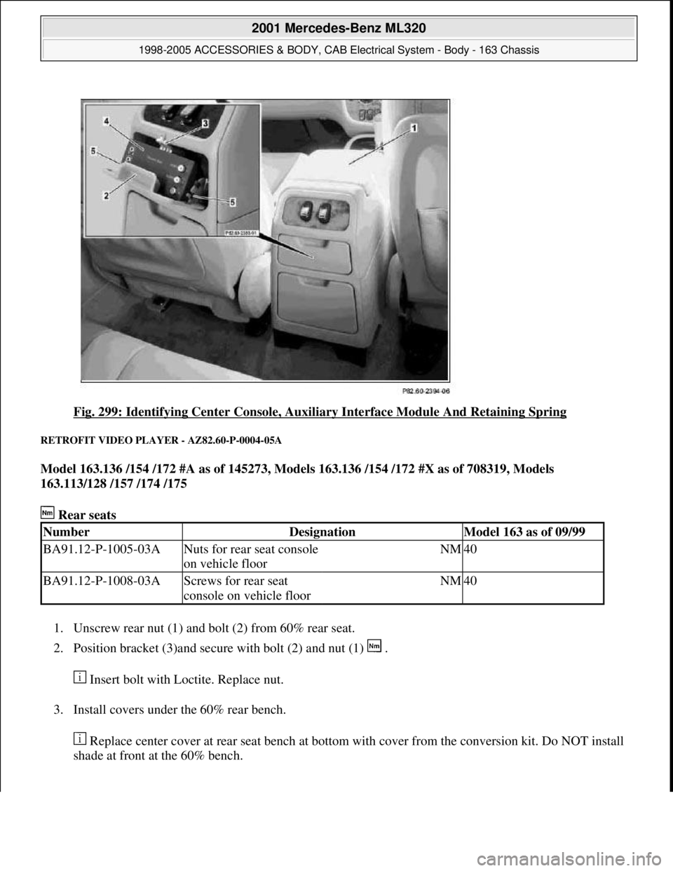
Fig. 299: Identifying Center Console, Auxiliary Interface Module And Retaining Spring
RETROFIT VIDEO PLAYER - AZ82.60-P-0004-05A
Model 163.136 /154 /172 #A as of 145273, Models 163.136 /154 /172 #X as of 708319, Models
163.113/128 /157 /174 /175
Rear seats
1. Unscrew rear nut (1) and bolt (2) from 60% rear seat.
2. Position bracket (3)and secure with bolt (2) and nut (1) .
Insert bolt with Loctite. Replace nut.
3. Install covers under the 60% rear bench.
Replace center cover at rear seat bench at bottom with cover from the conversion kit. Do NOT install
shade at front at the 60% bench.
NumberDesignationModel 163 as of 09/99
BA91.12-P-1005-03ANuts for rear seat console
on vehicle floorNM40
BA91.12-P-1008-03AScrews for rear seat
console on vehicle floorNM40
2001 Mercedes-Benz ML320
1998-2005 ACCESSORIES & BODY, CAB Electrical System - Body - 163 Chassis
me
Saturday, October 02, 2010 3:30:12 PMPage 384 © 2006 Mitchell Repair Information Company, LLC.
Page 1889 of 4133
Rear seats
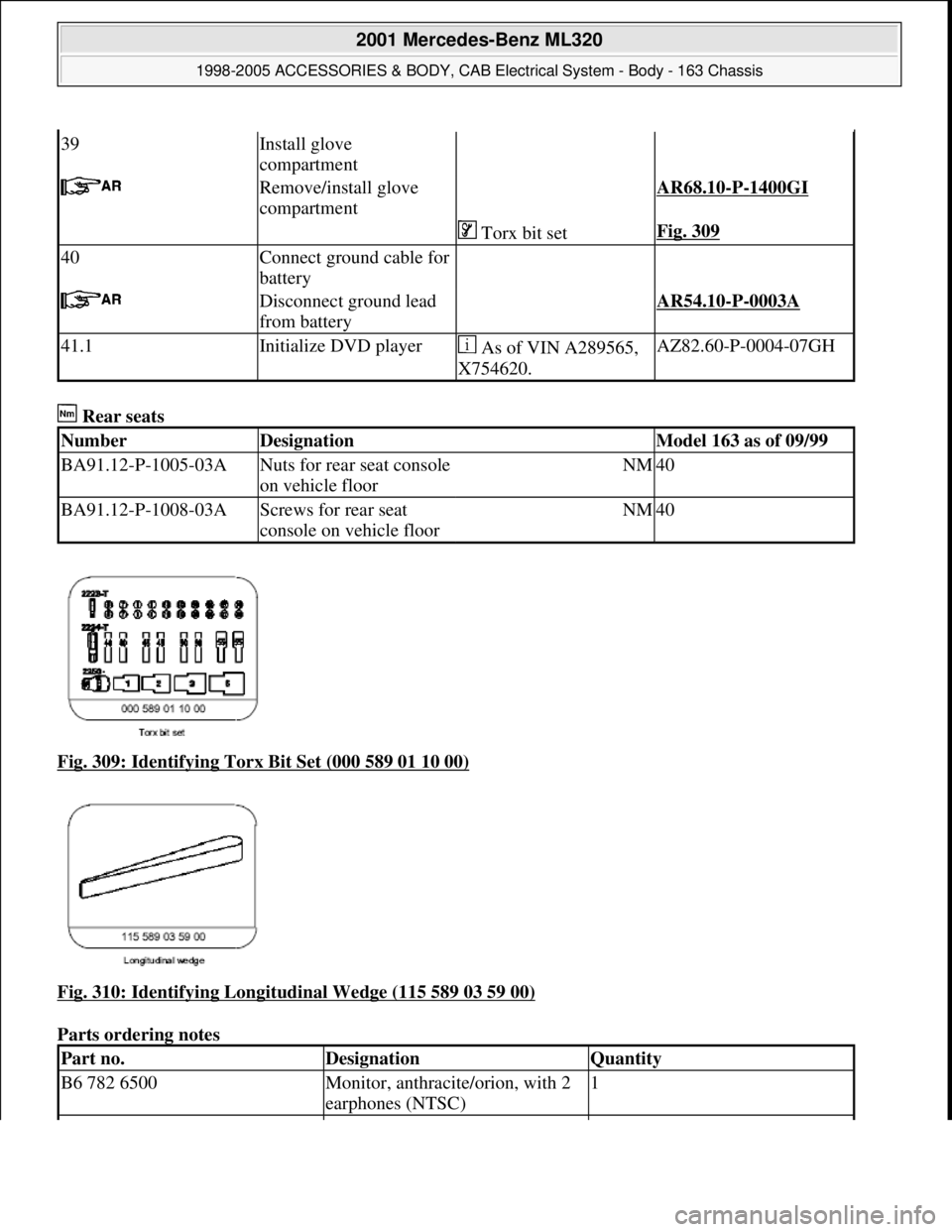
Fig. 309: Identifying Torx Bit Set (000 589 01 10 00)
Fig. 310: Identifying Longitudinal Wedge (115 589 03 59 00)
Parts ordering notes
39Install glove
compartment
Remove/install glove
compartment AR68.10-P-1400GI
Torx bit setFig. 309
40Connect ground cable for
battery
Disconnect ground lead
from battery AR54.10-P-0003A
41.1Initialize DVD player As of VIN A289565,
X754620.AZ82.60-P-0004-07GH
NumberDesignationModel 163 as of 09/99
BA91.12-P-1005-03ANuts for rear seat console
on vehicle floorNM40
BA91.12-P-1008-03AScrews for rear seat
console on vehicle floorNM40
Part no.DesignationQuantity
B6 782 6500Monitor, anthracite/orion, with 2
earphones (NTSC)1
2001 Mercedes-Benz ML320
1998-2005 ACCESSORIES & BODY, CAB Electr ical System - Body - 163 Chassis
me
Saturday, October 02, 2010 3:30:12 PMPage 394 © 2006 Mitchell Repair Information Company, LLC.
Page 2042 of 4133

3. Normalize side power windows. See NORMALIZING POWER WINDOWS .
4. Start engine and run at idle. Turn steering wheel from one lock position to the other to activate steering
angle sensor. Center steering wheel. Message "EI. STAB. PROGRAM GO TO GARAGE" should erase
from multifunction display panel.
5. If equipped, normalize tilting/sliding roof. See NORMALIZING TILTING/SLIDING ROOF
.
6. If equipped, normalize memory power seats, steering column and outside mirror if components are
installed. See NORMALIZING MEMORY POWER SEATS, STEERING COLUMN & OUTSIDE
MIRROR .
Normalizing Power Windows
1. Completely close each window with manual switch. Hold switch in closed position for .3 second.
2. Repeat procedure for each power window.
Normalizing Memory Power Seats, Steering Column & Outside Mirror
1. Using manual switch, move seat to each end position and hold for .3 second. Repeat procedure for each
switch except rear stop of backrest.
2. Repeat procedure for end positions of steering wheel and outside mirrors.
Normalizing Tilting/Sliding Roof
Open roof with SR switch until mechanical stop is reached. Continue to press switch for .5 seconds.
Setting Time
1. Use bottom left button on steering wheel to scroll through menus on instrument cluster to "Settings"
menu.
2. Move selection marker with + or - button to "Time" submenu.
3. Press up or down arrows to "Clock, hours" setting. Confirm selection marker is on the hour setting.
4. Press + or - to set hour. Press reset knob in instrument cluster to confirm.
5. Move selection marker with + or - button to "Time" submenu.
6. Press up or down arrows to "Clock, minutes" setting. Confirm selection marker is on the minutes setting.
7. Press + or - to set minute. Press reset knob in instrument cluster to confirm.
TESTING
If generator malfunctions, check for Diagnostic Trouble Codes (DTCs) in Motor Electronics Sequential Fuel
Injection (ME-SFI) system. See appropriate SELF-DIAGNOSTICS article in ENGINE PERFORMANCE. If
cause of generator malfunction is not engine performance related, replace generator.
RETRIEVING & ERASING DIAGNOSTIC TROUBLE CODES
NOTE: Before replacing any component that scan tool suggests are faulty, ensure that
all wiring connections and harness connectors are okay. Ensure that power and
2001 Mercedes-Benz ML320
2001-04 STARTING & CHARGING SYSTEMS Generators & Regulators - 163 Chassis
me
Saturday, October 02, 2010 3:20:32 PMPage 8 © 2006 Mitchell Repair Information Company, LLC.
Page 2352 of 4133
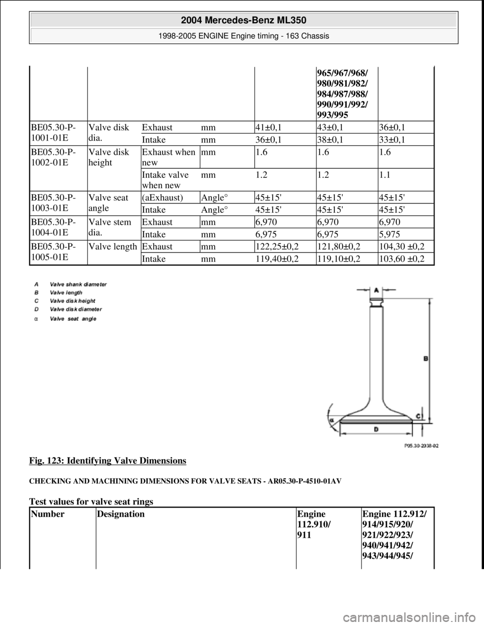
Fig. 123: Identifying Valve Dimensions
CHECKING AND MACHINING DIMENSIONS FOR VALVE SEATS - AR05.30-P-4510-01AV
Test values for valve seat rings
965/967/968/
980/981/982/
984/987/988/
990/991/992/
993/995
BE05.30-P-
1001-01EValve disk
dia.Exhaustmm41±0,143±0,136±0,1
Intakemm36±0,138±0,133±0,1
BE05.30-P-
1002-01EValve disk
heightExhaust when
newmm1.61.61.6
Intake valve
when newmm1.21.21.1
BE05.30-P-
1003-01EValve seat
angle(aExhaust)Angle°45±15'45±15'45±15'
IntakeAngle°45±15'45±15'45±15'
BE05.30-P-
1004-01EValve stem
dia.Exhaustmm6,9706,9706,970
Intakemm6,9756,9755,975
BE05.30-P-
1005-01EValve lengthExhaustmm122,25±0,2121,80±0,2104,30 ±0,2
Intakemm119,40±0,2119,10±0,2103,60 ±0,2
NumberDesignationEngine
112.910/
911Engine 112.912/
914/915/920/
921/922/923/
940/941/942/
943/944/945/
2004 Mercedes-Benz ML350
1998-2005 ENGINE Engine timing - 163 Chassis
me
Saturday, October 02, 2010 3:39:39 PMPage 111 © 2006 Mitchell Repair Information Company, LLC.
Page 2355 of 4133
Commercially available tools
Workshop equipment
3Machin valve seat
ring in cylinder head
*WE58.40-Z-
1009-21A
*WE58.40-Z-
1010-21A
Observe tool manufacturer's operating instructions, maintain
dimensions in accordance with checking and machining
dimensions. ?
Checking and machining dime nsions for valve seatsAR05.30-P-
4510-01AV
If the measurements after machining are less than the
specification ?
Replace valve seat ring.AR05.30-P-
3831AV
Inspection
4Measure seat width Correct valve seat width if necessary.AR05.30-P-
4510-01AV
5Insert valve and
inspect for leaks Grind valve with valve grinding compound before
installation.
*WH58.30-Z-
1020-13A
6Measure valve set-
back to cylinder head
If measurement is less than minimum dimension no further
correct valve clearance compensation is possible; replace valve
seat ring or cylinder head ?AR05.30-P-
4100-01AV
Replace valve seat ring. ?
The valve must always be rep laced after installing a new
valve seat ring. AR05.30-P-
3831AV
Install
7Install valves AR05.30-P-
3511AV
NumberDesignation
WH58.30-Z-1020-13AVacuum testing unit
WE58.40-Z-1009-21AValve seat turning device
WE58.40-Z-1010-21AValve seat turning device
2004 Mercedes-Benz ML350
1998-2005 ENGINE Engine timing - 163 Chassis
me
Saturday, October 02, 2010 3:39:39 PMPage 114 © 2006 Mitchell Repair Information Company, LLC.