radio MERCEDES-BENZ ML350 1997 Complete Repair Manual
[x] Cancel search | Manufacturer: MERCEDES-BENZ, Model Year: 1997, Model line: ML350, Model: MERCEDES-BENZ ML350 1997Pages: 4133, PDF Size: 88.89 MB
Page 5 of 4133
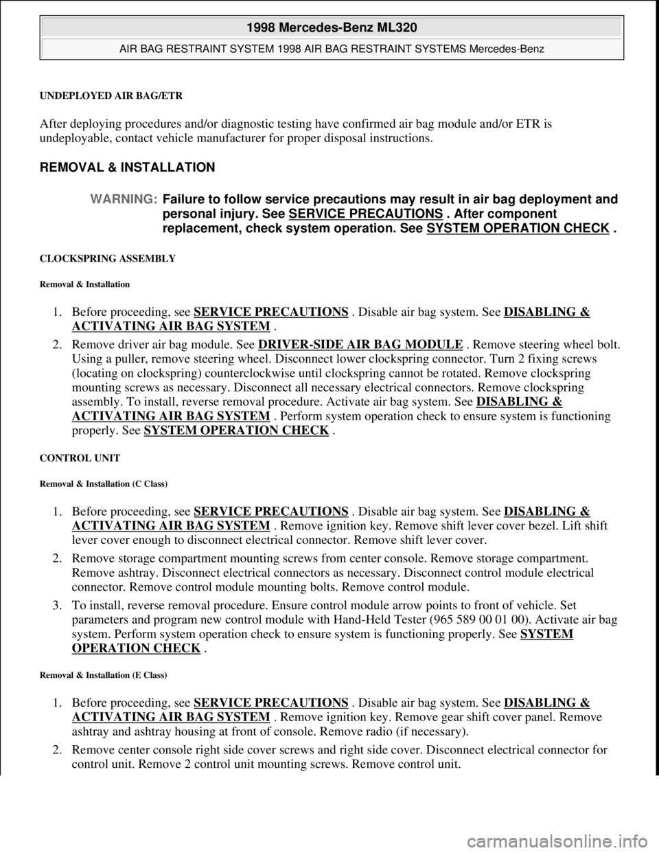
UNDEPLOYED AIR BAG/ETR
After deploying procedures and/or diagnostic testing have confirmed air bag module and/or ETR is
undeployable, contact vehicle manufacturer for proper disposal instructions.
REMOVAL & INSTALLATION
CLOCKSPRING ASSEMBLY
Removal & Installation
1. Before proceeding, see SERVICE PRECAUTIONS . Disable air bag system. See DISABLING &
ACTIVATING AIR BAG SYSTEM .
2. Remove driver air bag module. See DRIVER
-SIDE AIR BAG MODULE . Remove steering wheel bolt.
Using a puller, remove steering wheel. Disconnect lower clockspring connector. Turn 2 fixing screws
(locating on clockspring) counterclockwise until clockspring cannot be rotated. Remove clockspring
mounting screws as necessary. Disconnect all necessary electrical connectors. Remove clockspring
assembly. To install, reverse removal procedure. Activate air bag system. See DISABLING &
ACTIVATING AIR BAG SYSTEM . Perform system operation check to ensure system is functioning
properly. See SYSTEM OPERATION CHECK
.
CONTROL UNIT
Removal & Installation (C Class)
1. Before proceeding, see SERVICE PRECAUTIONS . Disable air bag system. See DISABLING &
ACTIVATING AIR BAG SYSTEM . Remove ignition key. Remove shift lever cover bezel. Lift shift
lever cover enough to disconnect electrical connector. Remove shift lever cover.
2. Remove storage compartment mounting screws from center console. Remove storage compartment.
Remove ashtray. Disconnect electrical connectors as necessary. Disconnect control module electrical
connector. Remove control module mounting bolts. Remove control module.
3. To install, reverse removal procedure. Ensure control module arrow points to front of vehicle. Set
parameters and program new control module with Hand-Held Tester (965 589 00 01 00). Activate air bag
system. Perform system operation check to ensure system is functioning properly. See SYSTEM
OPERATION CHECK .
Removal & Installation (E Class)
1. Before proceeding, see SERVICE PRECAUTIONS . Disable air bag system. See DISABLING &
ACTIVATING AIR BAG SYSTEM . Remove ignition key. Remove gear shift cover panel. Remove
ashtray and ashtray housing at front of console. Remove radio (if necessary).
2. Remove center console right side cover screws and right side cover. Disconnect electrical connector for
control unit. Remove 2 control unit mounting screws. Remove control unit. WARNING:Failure to follow service precautions may result in air bag deployment and
personal injury. See SERVICE PRECAUTIONS
. After component
replacement, check system operation. See SYSTEM OPERATION CHECK
.
1998 Mercedes-Benz ML320
AIR BAG RESTRAINT SYSTEM 1998 AIR BAG RESTRAINT SYSTEMS Mercedes-Benz
me
Saturday, October 02, 2010 3:33:13 PMPage 5 © 2006 Mitchell Repair Information Company, LLC.
Page 6 of 4133
3. To install, reverse removal procedure. Ensure control module arrow points to front of vehicle. Set
parameters and program new control module with Hand-Held Tester (965 589 00 01 00). Activate air bag
system. Perform system operation check to ensure system is functioning properly. See SYSTEM
OPERATION CHECK .
Removal & Installation (S Class)
1. Before proceeding, see SERVICE PRECAUTIONS . Disable air bag system. See DISABLING &
ACTIVATING AIR BAG SYSTEM . Remove ignition key. Remove radio. Remove ashtray. Remove
wooden surround for ashtray. Remove shift lever cover mounting screws. Push shift lever cover toward
rear of vehicle and remove in an upward direction.
2. Remove center console cover screws. Remove center console cover by pulling from bottom in an upward
direction. When removing covers, disconnect electrical connectors as necessary. Disconnect control
module electrical connector. Remove control module.
3. To install, reverse removal procedure. Ensure control module arrow points to front of vehicle. Set
parameters and program new control module with Hand-Held Tester (965 589 00 01 00). Activate air bag
system. Perform system operation check to ensure system is functioning properly. See SYSTEM
OPERATION CHECK .
Removal & Installation (SL Class)
1. Before proceeding, see SERVICE PRECAUTIONS . Disable air bag system. See DISABLING &
ACTIVATING AIR BAG SYSTEM . Remove ignition key. Remove radio. Push up and pull out heater
control panel. Unplug 2 connectors. Remove screw in middle of storage tray.
2. Bend up at top corners and lift out storage tray. Remove screws below storage tray. Lift wood trim panel
at rear, pull down and out of catches. Unplug switch connectors and remove wood trim panel. Unplug
connectors at control unit and remove Torx mounting screws. Remove control unit.
3. To install, reverse removal procedure. Ensure control module arrow points to front of vehicle. Set
parameters and program new control module with Hand-Held Tester (965 589 00 01 00). Activate air bag
system. Perform system operation check to ensure system is functioning properly. See SYSTEM
OPERATION CHECK .
Removal & Installation (CLK 320 & SLK 230)
1. Before proceeding, see SERVICE PRECAUTIONS . Disable air bag system. See DISABLING &
ACTIVATING AIR BAG SYSTEM . Remove ignition key. Remove cover on center console. Remove
cover on shift lever. Remove ash tray housing with storage compartment at front of center console.
Unplug connectors at control unit and remove Torx mounting screws. Remove control unit.
2. To install, reverse removal procedure. Ensure control module arrow points to front of vehicle. Set
parameters and program new control module with Hand-Held Tester (965 589 00 01 00). Activate air bag
system. Perform system operation check to ensure system is functioning properly. See SYSTEM
OPERATION CHECK .
DRIVER-SIDE AIR BAG MODULE
NOTE: Air bag module and steering wheel must be replaced following a collision in
1998 Mercedes-Benz ML320
AIR BAG RESTRAINT SYSTEM 1998 AIR BAG RESTRAINT SYSTEMS Mercedes-Benz
me
Saturday, October 02, 2010 3:33:13 PMPage 6 © 2006 Mitchell Repair Information Company, LLC.
Page 51 of 4133

1 Contents
IntroductionProduct information .......................... 7
Roadside assistance ......................... 10
Where to find it ................................ 14
Reporting Safety Defects ................ 16Instruments and controlsInstruments and controls ............... 18
Center console .............................. 20
Overhead control panel ............... 21OperationVehicle keys ...................................... 24
Start lock-out .................................... 25
General notes on the
central locking system ............... 26
Central locking system ................... 26
Radio frequency
remote control .............................. 26
Unlocking the liftgate .................. 28
Panic button .................................. 28
Mechanical keys ........................... 29Doors ................................................. 30
Central locking switch .................... 32
Automatic central locking .......... 32
Emergency unlocking in case
of accident ................................... 33
Liftgate .............................................. 34
Antitheft alarm system ................... 35
Tow-away alarm and
glass breakage sensor ............... 36
Seats, front ....................................... 37
Manual seats ................................ 39
Power seats ................................... 40
Head restraint ...............................41
Heated seats ..................................... 44
Seat belts and integrated
restraint system .......................... 46
Seat belts .......................................... 46
Seat belt nonusage
warning system ............................ 47
BabySmart
TM airbag
deactivation system ................... 53
Self-test BabySmart
TM
without special child
seat installed ................................ 53Supplemental restraint
system (SRS) ................................ 54
Emergency tensioning
retractor (ETR) ............................. 55
Airbags .............................................. 56
Safety guidelines for the
seat belt, emergency
tensioning retractor
and airbag ..................................... 63
Infant and child
restraint systems .......................... 65
Adjustable steering wheel .............. 70
Inside rear view mirror .................. 71
Antiglare night position .............. 71
Exterior rear view mirrors ............. 73
Exterior rear view mirror,
electrically folding ....................... 75
Instrument cluster ........................... 76
Indicator lamps in the
instrument cluster ...................... 78
Trip computer ................................... 83
Flexible service system (FSS) ........ 87
Engine oil level indicator ................ 89
Exterior lamp switch ....................... 90
Page 52 of 4133

2 Contents
Fog lamp switch
(except Canada) ........................... 92
Fog lamp switch
(Canada only) .............................. 93
Hazard warning flasher
switch ............................................ 94
Headlamp cleaning system ............ 94
Windshield wiper/washer
switch ............................................ 95
Rear window wiper/washer ........... 96
Climate control ................................. 98
Basic setting – Heater ............... 100
Basic setting –
Air conditioner ........................... 100
Special setting ............................ 101
Dust filter .................................... 102
Air recirculation ......................... 102
Rear window defroster .............. 103
Power windows ............................... 104
Rear quarter windows ................... 106
Sliding/pop-up roof ....................... 107
Skyview Top .................................... 109
Interior lighting ..............................110
Sun visors ........................................113Illuminated vanity mirrors ........... 113
Interior ............................................. 114
Storage compartments,
armrest and cup holder ............ 114
Glove box ...................................... 115
Armrest in rear bench seat ........... 117
Ashtrays ........................................... 118
Lighter .............................................. 119
Split rear seat bench ..................... 120
Easy entry/exit feature ............. 123
Rear seat head restraints ......... 124
Third row seats .............................. 126
Removable cargo floor plates ...... 129
Enlarged cargo area .......................131
Cargo tie-down rings .....................132
Hooks ...............................................133
Partition net ....................................133
Loading instructions ......................136
Cargo area cover blind ..................137
Telephone, general .........................139
Cellular telephone ..........................139
Garage door opener ....................... 140
DrivingControl and operation of
radio transmitters ..................... 146
The first 1 000 miles
(1 500 km) ................................. 147
Maintenance ................................... 147
Tele Aid ........................................... 148
Catalytic converter ........................ 160
Emission control ............................ 161
Steering lock ................................... 162
Starting and turning off
the engine .................................. 164
Automatic transmission ............... 165
Parking brake ................................. 173
Driving instructions ...................... 174
Drive sensibly – save fuel ......... 174
Drinking and driving ................. 174
Pedals ........................................... 174
Power assistance ........................ 175
Brakes .......................................... 175
Driving off ................................... 176
Parking ........................................ 176
Tires ............................................. 177
Page 72 of 4133
22 Contents - Operation
Te ch n ica l
data Instruments
and controlsOperationDrivingInstrument
cluster displayPractical hints Car care Index
OperationVehicle keys ...................................... 24
Start lock-out .................................... 25
General notes on the
central locking system ............... 26
Central locking system ................... 26
Radio frequency
remote control .............................. 26
Unlocking the liftgate .................. 28
Panic button .................................. 28
Mechanical keys ........................... 29
Doors .................................................. 30
Central locking switch .................... 32
Automatic central locking .......... 32
Emergency unlocking in case
of accident .................................... 33
Liftgate ............................................... 34
Antitheft alarm system ................... 35
Tow - aw ay a lar m a n d
glass breakage sensor ................ 36
Seats, front ........................................ 37
Manual seats ................................. 39
Power seats ................................... 40Head restraint ...............................41
Heated seats ..................................... 44
Seat belts and integrated
restraint system .......................... 46
Seat belts .......................................... 46
Seat belt nonusage
warning system ............................ 47
BabySmart
TM airbag
deactivation system ................... 53
Self-test BabySmart
TM
without special child
seat installed ................................ 53
Supplemental restraint
system (SRS) ............................... 54
Emergency tensioning
retractor (ETR) ............................ 55
Airbags .............................................. 56
Safety guidelines for the
seat belt, emergency
tensioning retractor
and airbag ..................................... 63
Infant and child
restraint systems ......................... 65
Adjustable steering wheel .............. 70
Inside rear view mirror ...................71Antiglare night position .............. 71
Exterior rear view mirrors ............. 73
Exterior rear view mirror,
electrically folding ....................... 75
Instrument cluster ........................... 76
Indicator lamps in the
instrument cluster ...................... 78
Trip computer ................................... 83
Flexible service system (FSS) ........ 87
Engine oil level indicator ................ 89
Exterior lamp switch ....................... 90
Fo g la mp sw itch
(except Canada) .......................... 92
Fo g la mp sw itch
(Canada only) .............................. 93
Hazard warning flasher
switch ............................................ 94
Headlamp cleaning system ............ 94
Windshield wiper/washer
switch ............................................ 95
Rear window wiper/washer ........... 96
Climate control ................................. 98
Basic setting – Heater ............... 100
Page 76 of 4133
26 Central locking system
Te ch n ica l
data Instruments
and controlsOperationDrivingInstrument
cluster displayPractical hints Car care Index
General notes on the central locking system
If the key in the steering lock is in position 1 or 2, the
vehicle cannot be locked or unlocked with the remote
control.
If the vehicle cannot be locked or unlocked:
•Check the batteries of the remote control, see
page 270.
•Synchronize the remote control, see page 271.Central locking system
(Radio frequency remote control)
The master key has an integrated radio frequency
remote control.
Due to the extended operational range of the remote
control, it could be possible to unintentionally lock or
unlock the vehicle by pressing the transmit button.
The vehicle doors, liftgate and fuel filler flap can be
centrally locked and unlocked via remote control.
With vehicle centrally locked, the liftgate can also be
unlocked by using the remote control.
If the key in the steering lock is in position 1 or 2, the
vehicle cannot be locked or unlocked with the remote
control.
Page 189 of 4133
139 Interior equipment
Te ch n ica l
data Instruments
and controlsOperationDrivingInstrument
cluster displayPractical hints Car care Index Telephone, general
See separate instruction manual for instructions on how
to operate the telephone.
Cellular telephone
Wa r n i n g !
A driver’s attention to the road must always be his /
her primary focus when driving. For your safety
and the safety of others, we recommend that you
pull over to a safe location and stop before placing
or taking a telephone call. If you choose to use the
telephone while driving, please use the hands-free
device and only use the telephone when road and
traffic conditions permit.Some jurisdictions prohibit the driver from using a
cellular telephone while driving a vehicle.Bear in mind that at a speed of just 30 mph
(approximately 50 km / h), your vehicle is covering
a distance of approximately 50 feet (approximately
14 m ) e v e r y s e c o n d .
Never operate radio transmitters equipped with a
built-in or attached antenna (i.e. without being
connected to an external antenna) from inside the
vehicle while the engine is running. Doing so could
lead to a malfunction of the vehicle’s electronic
system, possibly resulting in an accident and
personal injury.Wa r n i n g !
Some jurisdictions prohibit the driver from using a
cellular telephone while driving a vehicle. Whether
or not prohibited by law, for safety reasons, the
driver should not use the cellular telephone while
the vehicle is in motion.
Stop the vehicle in an safe location before
answering or placing a call.
Page 195 of 4133
145 Contents - Driving
Te ch n ica l
data Instruments
and controlsOperationDrivingInstrument
cluster displayPractical hints Car care Index
DrivingControl and operation of
radio transmitters ..................... 146
The first 1 000 miles
(1 500 km) ................................. 147
Maintenance ................................... 147
Tele Aid ........................................... 148
Catalytic converter ........................ 160
Emission control ............................ 161
Steering lock ................................... 162
Starting and turning off
the engine .................................. 164
Automatic transmission ............... 165
Parking brake ................................. 173Driving instructions .......................174
Drive sensibly – save fuel .........174
Drinking and driving .................174
Pedals ...........................................174
Power assistance ........................ 175
Brakes .......................................... 175
Driving off .................................... 176
Parking ......................................... 176
Tires ............................................. 177
Snow chains ............................... 179
Winter driving instructions ......180
Deep water ...................................181
Passenger compartment ............182
Traveling abroad .........................182Off-Road driving ............................. 183
Trailer towing ................................. 190
Cruise control ................................. 196
Brake assist system (BAS) ............ 199
Antilock brake system (ABS) ....... 201
Four-wheel electronic
traction system (4-ETS+) ..........203
Electronic brake
proportioning (EBP) ..................204
Electronic stability program
(ESP) ...........................................205
Transmission control –
LOW RANGE mode ...................209
What you should know
at the gas station ....................... 212
Check regularly and
before a long trip ...................... 215
Page 196 of 4133
146 Control and operation of radio transmitters
Te ch n ica l
data Instruments
and controlsOperationDrivingInstrument
cluster displayPractical hints Car care Index
Control and operation of radio transmitters
MCS, radio and telephone
1 Observe all legal requirements.
Telephones and two-way radio
Radio transmitters, such as a portable telephone or a
citizens band unit should only be used inside the
vehicle if they are connected to an antenna that is
installed on the outside of the vehicle.
Refer to the radio transmitter operation instructions
regarding use of an external antenna.
Wa r n i n g !
Please do not forget that your primary
responsibility is to drive the vehicle. Only operate
the MCS, radio or telephone
1 if road and traffic
conditions permit.
Bear in mind that at a speed of just 30 mph
(approximately 50 km / h), your vehicle is covering
a distance of approximately 50 feet (approximately
14 m ) e v e r y s e c o n d .
Wa r n i n g !
Never operate radio transmitters equipped with a
built-in or attached antenna (i.e. without being
connected to an external antenna) from inside the
vehicle while the engine is running. Doing so could
lead to a malfunction of the vehicle’s electronic
system, possibly resulting in an accident and
personal injury.
Page 207 of 4133
157 Tele Aid
Te ch n ica l
data Instruments
and controlsOperationDrivingInstrument
cluster displayPractical hints Car care Index Important!
If the indicator lamp continues to flash or the system
does not reset, contact the Response Center at
1-800-756-9018 (in the USA) or 1-888-923-8367 (in
Canada), or Mercedes-Benz Client Assistance at
1-800-FOR-MERCedes (1-800-367-6372) in the USA or
Customer Service at 1-800-387-0100 in Canada.
Notes:
The indicator lamp for the respective button flashes
until the call is concluded and this can only be
completed by a Response Center or Client Assistance
Center representative, except Roadside assistance and
Information calls, which can also be terminated by
using the End button on the MCS unit.
When a Tele Aid call has been initiated, the MCS system
audio is muted and the selected mode (radio, tape or
CD) pauses. The optional cellular phone (if installed)
switches off. If you must use this phone, the vehicle
must be parked. Disconnect the coiled cord and place
the call. The navigation system (if engaged) will
continue to run. A pop-up window will appear in the
MCS display to indicate that a Tele Aid call is in
progress.Remote door unlock
In the case you have your vehicle locked unintentionally
(e.g. key inside vehicle), and the reserve key is not
handy, contact the Mercedes-Benz Response Center at
1-800-756-9018 (in the USA) or 1-888-923-8367 (in
Canada). You will be asked to provide your password
which you provided when you completed the subscriber
agreement.
Then return to your vehicle and pull outside handle of
liftgate for a minimum of 20 seconds until the “SOS”
button is flashing.
As an alternative, you may unlock the vehicle via
Internet using the ID and password sent to you shortly
after the completion of your Acquaintance Call.
The Response Center will then unlock your vehicle with
the remote door unlocking feature.
Note:
The remote door unlock feature is available if the
relevant cellular phone network is available.
The SOS button will f lash and the message
“EMERGENCY CALL – CALL CONNECTED” will appear
in t he MCS display to indica te receipt of t he d oor unlock
command.