fold seats MERCEDES-BENZ ML350 1997 Complete User Guide
[x] Cancel search | Manufacturer: MERCEDES-BENZ, Model Year: 1997, Model line: ML350, Model: MERCEDES-BENZ ML350 1997Pages: 4133, PDF Size: 88.89 MB
Page 489 of 4133
22
Contents - Operation
Te ch n ica l
data
Instruments
and controls Operation
Driving Instrument
cluster display Practical hints Car care Index
OperationVehicle keys ...................................... 24
Start lock-out .................................... 25
General notes on the central locking system ............... 26
Central locking system ................... 26 Radio frequency
remote control .............................. 26
Unlocking the liftgate .................. 28
Panic button .................................. 28
Mechanical keys ........................... 29
Doors .................................................. 30
Central locking switch .................... 32 Automatic central locking .......... 32
Emergency unlocking in case of accident .................................... 33
Liftgate ............................................... 34
Antitheft alarm system ................... 35
Tow - aw ay a lar m a n d glass breakage sensor ................ 36
Seats, front ........................................ 37 Manual seats ................................. 39
Power seats ................................... 40 Head restraint ...............................41
Heated seats ..................................... 44
Seat belts and integrated restraint system .......................... 46
Seat belts .......................................... 46 Seat belt nonusage
warning system ............................ 47
BabySmart
TM airbag
deactivation system ................... 53
Self-test BabySmart
TM
without special child
seat installed ................................ 53
Supplemental restraint system (SRS) ............................... 54
Emergency tensioning retractor (ETR) ............................ 55
Airbags .............................................. 56 Safety guidelines for the
seat belt, emergency
tensioning retractor
and airbag ..................................... 63
Infant and child
restraint systems ......................... 65
Adjustable steering wheel .............. 70
Inside rear view mirror ...................71 Antiglare night position .............. 71
Exterior rear view mirrors ............. 73 Exterior rear view mirror,
electrically folding ....................... 75
Instrument cluster ........................... 76
Indicator lamps in the instrument cluster ...................... 78
Trip computer ................................... 83
Flexible service system (FSS) ........ 87
Engine oil level indicator ................ 89
Exterior lamp switch ....................... 90
Fo g la mp sw itch (except Canada) .......................... 92
Fo g la mp sw itch (Canada only) .............................. 93
Hazard warning flasher switch ............................................ 94
Headlamp cleaning system ............ 94
Windshield wiper/washer switch ............................................ 95
Rear window wiper/washer ........... 96
Climate control ................................. 98
Basic setting – Heater ............... 100
Page 587 of 4133
120
Interior equipment
Te ch n ica l
data
Instruments
and controls Operation
Driving Instrument
cluster display Practical hints Car care Index
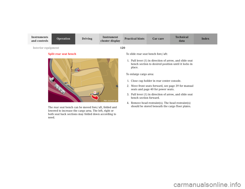
Split rear seat bench
The rear seat bench can be moved fore / aft, folded and
lowered to increase the cargo area. The left, right or
both seat back sections may folded down according to
need. To slide rear seat bench fore / aft:
1. Pull lever (1) in direction of arrow, and slide seat bench section to desired position until it locks in
place.
To enlarge cargo area: 1. Close cup holder in rear center console.
2. Move front seats forward, see page 39 for manual seats and page 40 for power seats.
3. Pull lever (1) in direction of arrow, and slide seat bench section forward.
4. Remove head restraint(s). The head restraint(s) should be stored beneath the cargo f loor plates.
Page 589 of 4133
122
Interior equipment
Te ch n ica l
data
Instruments
and controls Operation
Driving Instrument
cluster display Practical hints Car care Index
To return seat bench section to sitting position: 1. Pull lever (1) and raise seat bench section until it locks in place.
2. Pull lock button (2) up, and unfold seat back to upright position. Check for secure locking by
pushing and pulling on the backrest. The red
backrest lock indicators at the lock buttons (2) are
not visible in locked position.
3. Pull lever (1) in direction of arrow, and slide seat bench section rearward to desired position. 4. Install and adjust head restraint.
For installation of head restraints see page 124.
Wa r n i n g !
Failure to assure that seats are locked into place
could result in an increased chance of injury in an
accident.Never place hands under seat or near any moving
parts while a seat is being adjusted.
Page 590 of 4133
123
Interior equipment
Te ch n ica l
data
Instruments
and controls Operation
Driving Instrument
cluster display Practical hints Car care Index
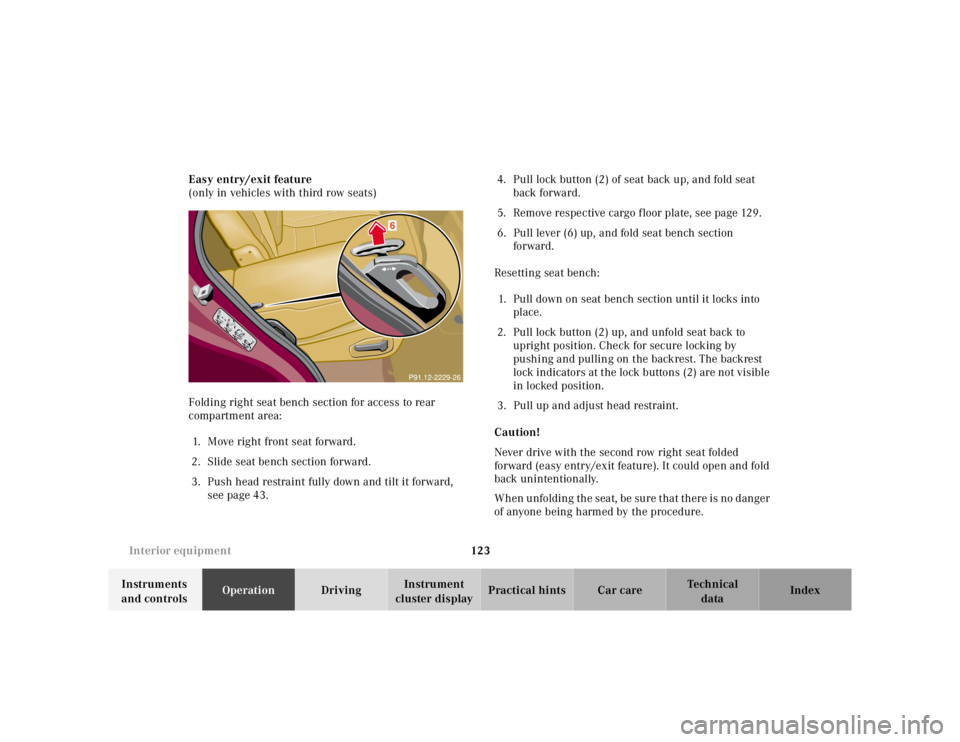
Easy entry/exit feature
(only in vehicles with third row seats)
Folding right seat bench section for access to rear
compartment area:
1. Move right front seat forward.
2. Slide seat bench section forward.
3. Push head restraint fully down and tilt it forward, see page 43. 4. Pull lock button (2) of seat back up, and fold seat
back forward.
5. Remove respective cargo floor plate, see page 129.
6. Pull lever (6) up, and fold seat bench section forward.
Resetting seat bench: 1. Pull down on seat bench section until it locks into place.
2. Pull lock button (2) up, and unfold seat back to upright position. Check for secure locking by
pushing and pulling on the backrest. The backrest
lock indicators at the lock buttons (2) are not visible
in locked position.
3. Pull up and adjust head restraint.
Caution!
Never drive with the second row right seat folded
forward (easy entry/exit feature). It could open and fold
back unintentionally.
When unfolding the seat, be sure that there is no danger
of anyone being harmed by the procedure.
Page 593 of 4133
126
Interior equipment
Te ch n ica l
data
Instruments
and controls Operation
Driving Instrument
cluster display Practical hints Car care Index
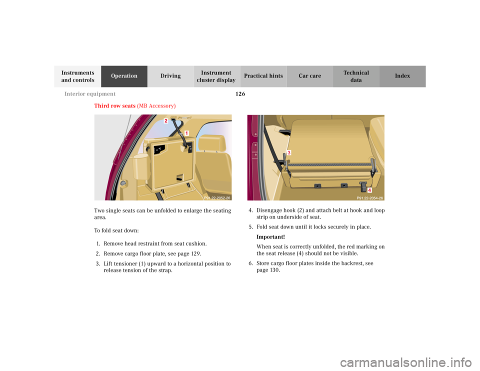
Third row seats (MB Accessory)
Two single seats can be unfolded to enlarge the seating
area.
To fold seat down: 1. Remove head restraint from seat cushion.
2. Remove cargo f loor plate, see page 129.
3. Lift tensioner (1) upward to a horizontal position to release tension of the strap. 4. Disengage hook (2) and attach belt at hook and loop
strip on underside of seat.
5. Fold seat down until it locks securely in place.
Important!
When seat is correctly unfolded, the red marking on
the seat release (4) should not be visible.
6. Store cargo floor plates inside the backrest, see page 130.
4
Page 594 of 4133
127
Interior equipment
Te ch n ica l
data
Instruments
and controls Operation
Driving Instrument
cluster display Practical hints Car care Index
7. Pull release lever (3) and unfold seat back until it
locks securely in place.
8. Install head restraint in seat back.
Note:
For removal and installation of head restraint refer to
rear seat head restraints on page 124.
To sto r e s ea t: 1. Remove head restraint from seat back.
2. Pull release lever (3) and fold seat back forward until it audibly locks securely in place. Place seat
belt between lever (3) and backrest.
3. Remove cargo floor plates from the backrest.
4. Pull seat release (4) and fold seat up. Engage hook (2) in ceiling mount. Pull on free end of strap
until tight.
5. Install head restraint in openings provided in seat cushion.
6. Install cargo floor plates, see page 129.
Wa r n i n g !
Failure to assure that seats are locked into place
could result in an increased chance of injury in an
accident.Never place hands under seat or near any moving
parts while a seat is being adjusted.For your protection, drive only with properly
positioned head restraints.Adjust head restraint to support the back of the
head approximately at ear level.
Page 714 of 4133
247
Tires, Wheels
Te ch n ica l
data
Instruments
and controls Operation Driving
Instrument
cluster display Practical hints
Car care Index
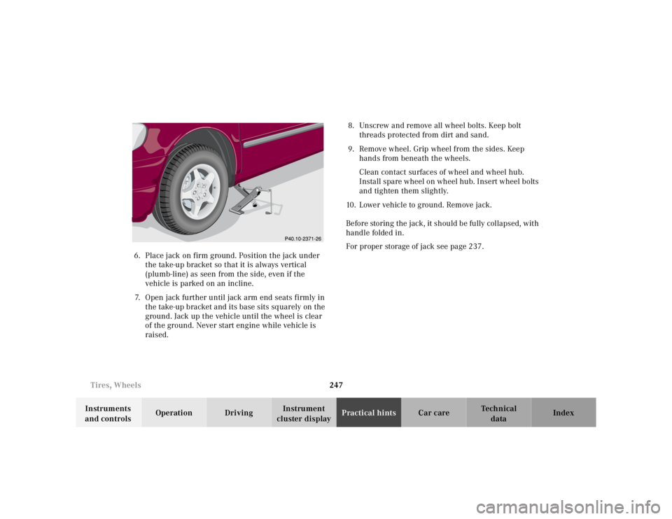
6. Place jack on firm ground. Position the jack under
t he take-up bracket so t hat it is always ve rtical
(plumb-line) as seen from the side, even if the
vehicle is parked on an incline.
7. Open jack further until jack arm end seats firmly in the take-up bracket and its base sits sq uarely on the
ground. Jack up the vehicle until the wheel is clear
of the ground. Never start engine while vehicle is
raised. 8. Unscrew and remove all wheel bolts. Keep bolt
threads protected from dirt and sand.
9. Remove wheel. Grip wheel from the sides. Keep hands from beneath the wheels.
Clean contact surfaces of wheel and wheel hub.
Install spare wheel on wheel hub. Insert wheel bolts
and tighten them slightly.
10. Lower vehicle to ground. Remove jack.
Before storing the jack, it should be fully collapsed, with
handle folded in.
For proper storage of jack see page 237.
Page 775 of 4133
308
Index
Te ch n ica l
data
Instruments
and controls Operation Driving
Instrument
cluster display Practical hints Car care
Index
Remote control ................................................................. 24 Battery replacement .................................................270
Changing batteries ...................................................270
Operation ..................................................................... 26
Synchronizing remote control ................................ 271
Removable cargo floor plates ....................................... 129
Replacement keys ............................................................ 25
Replacing bulbs ..............................................................260
Replacing wiper blade insert .......................................275
Reporting safety defects ................................................. 16
Reserve key ................................................................ 24, 25
Roadside assistance ......................................................... 10
Roadside assistance call See Tele Aid ............................................................... 148
Roof rack ......................................................................... 276
SSafety guidelines for the seat belt, emergency tensioning retractor and airbag ................................ 63
Screwdriver .....................................................................237
Seat belt warning lamp .................................................223
Seat belts ........................................................................... 46 Fastening ...................................................................... 48
Seat belt nonusage warning system ........................ 47 Unfastening .................................................................. 50
Warning lamp ........................................................... 223
Seat belts and integrated restraint system .................. 46
Seat bench ....................................................................... 120
Seats, folding (Third row seats) ................................... 126
Seats, front ........................................................................37 Heated seats .................................................................44
Manual seats ................................................................39
Power seats .................................................................. 40
Service indicator
See Flexible service system (FSS) ............................ 87
Side marker lamp .......................................................... 264
Skyview Top ....................................................................109 Emergency operation .............................................. 273
Sliding/pop-up roof ........................................................107 Emergency operation .............................................. 272
Express opening ........................................................108
Synchronizing .......................................................... 272
Snow chains ....................................................................179
SOS-call See Tele Aid ...............................................................148
Space-saver tire
Air pump ................................................................... 239
Spare parts service ....................................................... 284
Spare wheel ................................................................... 242 Space-saver tire ........................................................ 243
Page 792 of 4133
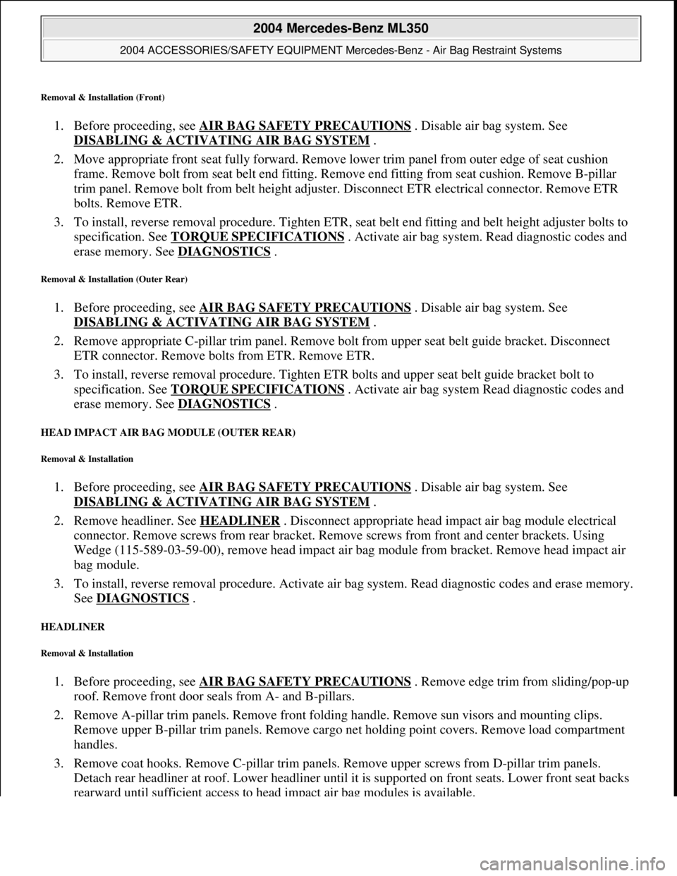
Removal & Installation (Front)
1. Before proceeding, see AIR BAG SAFETY PRECAUTIONS . Disable air bag system. See
DISABLING & ACTIVATI NG AIR BAG SYSTEM
.
2. Move appropriate front seat full y forward. Remove lower trim panel from outer edge of seat cushion
frame. Remove bolt from seat belt end fitting. Remove end fitting from seat cushion. Remove B-pillar
trim panel. Remove bolt from be lt height adjuster. Disconnect ET R electrical connector. Remove ETR
bolts. Remove ETR.
3. To install, reverse removal procedur e. Tighten ETR, seat belt end fitting and belt height adjuster bolts to
specification. See TORQUE SPECIFICATIONS
. Activate air bag system . Read diagnostic codes and
erase memory. See DIAGNOSTICS
.
Removal & Installation (Outer Rear)
1. Before proceeding, see AIR BAG SAFETY PRECAUTIONS . Disable air bag system. See
DISABLING & ACTIVATI NG AIR BAG SYSTEM
.
2. Remove appropriate C-pillar trim panel. Remove bolt from upper seat belt guide bracket. Disconnect
ETR connector. Remove bolts from ETR. Remove ETR.
3. To install, reverse removal proc edure. Tighten ETR bolts and upper seat belt guide bracket bolt to
specification. See TORQUE SPECIFICATIONS
. Activate air bag system Read diagnostic codes and
erase memory. See DIAGNOSTICS
.
HEAD IMPACT AIR BAG MODULE (OUTER REAR)
Removal & Installation
1. Before proceeding, see AIR BAG SAFETY PRECAUTIONS . Disable air bag system. See
DISABLING & ACTIVATI NG AIR BAG SYSTEM
.
2. Remove headliner. See HEADLINER
. Disconnect appropriate head im pact air bag module electrical
connector. Remove screws from rear bracket. Rem ove screws from front and center brackets. Using
Wedge (115-589-03-59-00), remove head impact air ba g module from bracket. Remove head impact air
bag module.
3. To install, reverse removal proce dure. Activate air bag system. Read diagnostic codes and erase memory.
See DIAGNOSTICS
.
HEADLINER
Removal & Installation
1. Before proceeding, see AIR BAG SAFETY PRECAUTIONS . Remove edge trim from sliding/pop-up
roof. Remove front door seals from A- and B-pillars.
2. Remove A-pillar trim panels. Remove front fold ing handle. Remove sun visors and mounting clips.
Remove upper B-pillar trim panels . Remove cargo net holding point c overs. Remove load compartment
handles.
3. Remove coat hooks. Remove C-pill ar trim panels. Remove upper screws from D-pillar trim panels.
Detach rear headliner at roof. Lower headliner until it is supported on front seats. Lower front seat backs
rearward until sufficient ac cess to head impact air ba
g modules is available.
2004 Mercedes-Benz ML350
2004 ACCESSORIES/SAFETY EQUIPMENT Merce des-Benz - Air Bag Restraint Systems
me
Saturday, October 02, 2010 3:40:40 PMPage 7 © 2006 Mitchell Repair Information Company, LLC.
Page 807 of 4133
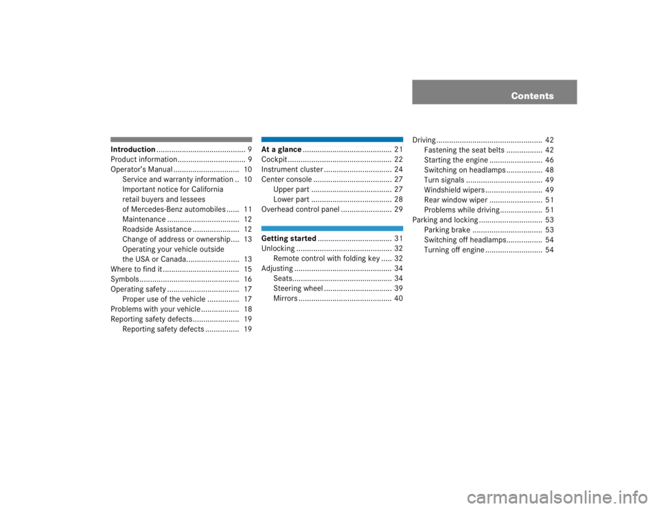
Contents
Introduction.......................................... 9
Product information ................................ 9
Operator’s Manual ............................... 10
Service and warranty information .. 10
Important notice for California
retail buyers and lessees
of Mercedes-Benz automobiles ...... 11
Maintenance .................................. 12
Roadside Assistance ...................... 12
Change of address or ownership.... 13
Operating your vehicle outside
the USA or Canada......................... 13
Where to find it .................................... 15
Symbols ............................................... 16
Operating safety .................................. 17
Proper use of the vehicle ............... 17
Problems with your vehicle .................. 18
Reporting safety defects...................... 19
Reporting safety defects ................ 19
At a glance.......................................... 21
Cockpit ................................................. 22
Instrument cluster ................................ 24
Center console ..................................... 27
Upper part ...................................... 27
Lower part ...................................... 28
Overhead control panel ........................ 29Getting started................................... 31
Unlocking ............................................. 32
Remote control with folding key ..... 32
Adjusting .............................................. 34
Seats............................................... 34
Steering wheel ................................ 39
Mirrors ............................................ 40Driving .................................................. 42
Fastening the seat belts ................. 42
Starting the engine ......................... 46
Switching on headlamps ................. 48
Turn signals .................................... 49
Windshield wipers ........................... 49
Rear window wiper ......................... 51
Problems while driving.................... 51
Parking and locking .............................. 53
Parking brake ................................. 53
Switching off headlamps................. 54
Turning off engine ........................... 54