MERCEDES-BENZ ML350 1997 Complete Repair Manual
ML350 1997
MERCEDES-BENZ
MERCEDES-BENZ
https://www.carmanualsonline.info/img/4/57306/w960_57306-0.png
MERCEDES-BENZ ML350 1997 Complete Repair Manual
Trending: climate control, parking brake, fuel tank capacity, wiper fluid, oil level, check engine light, check engine
Page 2051 of 4133
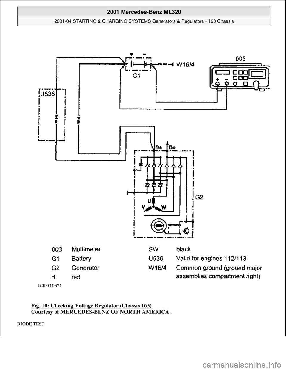
Fig. 10: Checking Voltage Regulator (Chassis 163)
Courtesy of MERCEDES-BENZ OF NORTH AMERICA.
DIODE TEST
2001 Mercedes-Benz ML320
2001-04 STARTING & CHARGING SYSTEMS Generators & Regulators - 163 Chassis
me
Saturday, October 02, 2010 3:20:32 PMPage 17 © 2006 Mitchell Repair Information Company, LLC.
Page 2052 of 4133
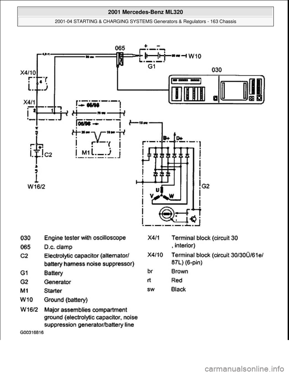
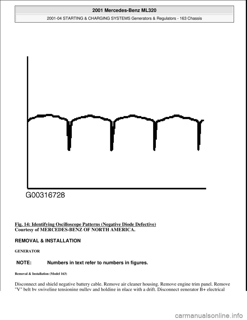
Connect DC clip-on probe from engine tester with oscilloscope to positive battery terminal. See Fig. 11. Start
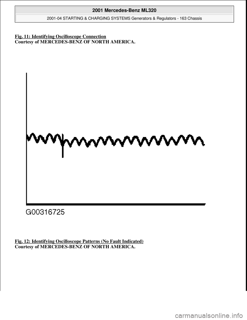
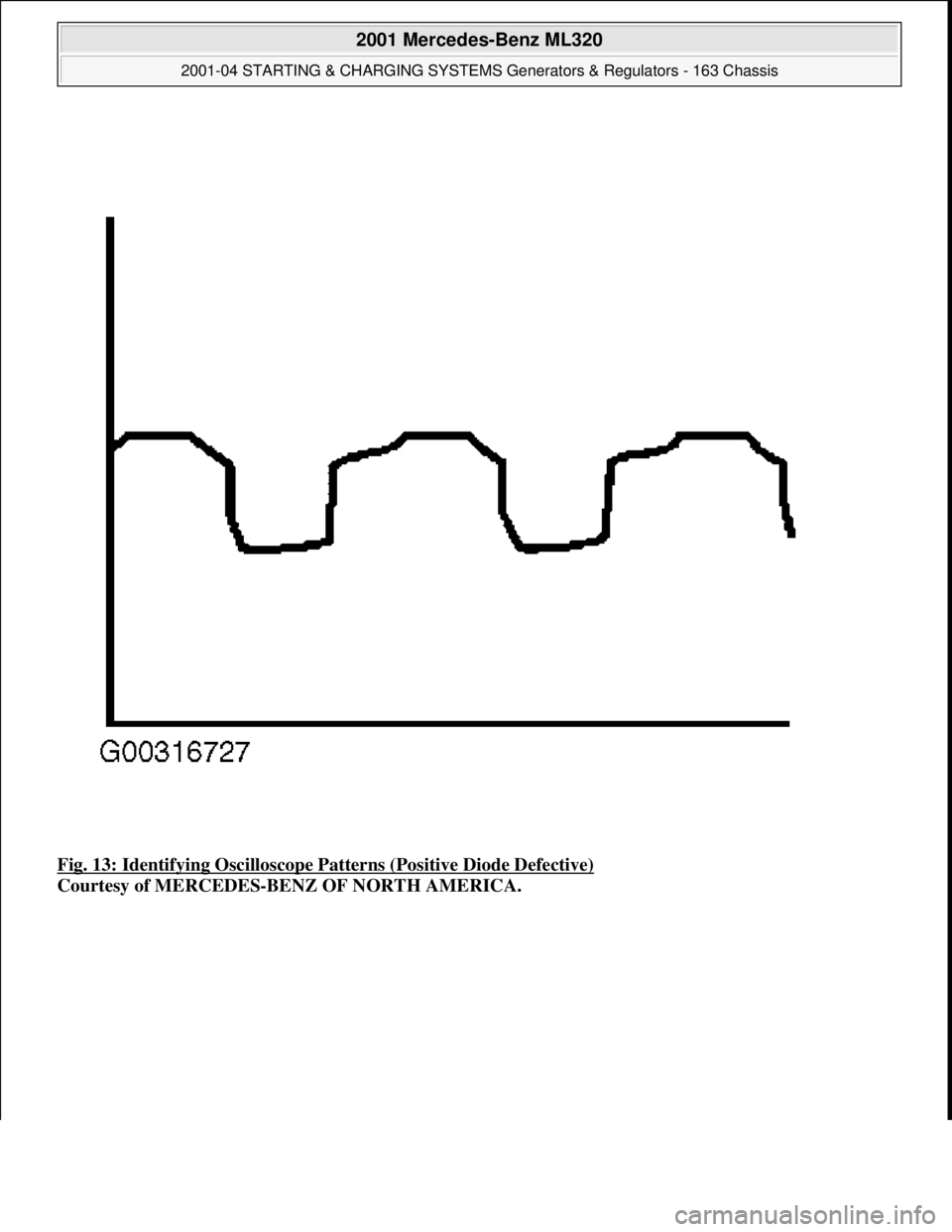
engine. Switch on low beam. Access diode test at 3000 RPM. See Fig. 12
-Fig. 14 . Replace generator as
necessar
y.
2001 Mercedes-Benz ML320
2001-04 STARTING & CHARGING SYSTEMS Generators & Regulators - 163 Chassis
me
Saturday, October 02, 2010 3:20:32 PMPage 18 © 2006 Mitchell Repair Information Company, LLC.
Page 2053 of 4133
2001 Mercedes-Benz ML320
2001-04 STARTING & CHARGING SYSTEMS Generators & Regulators - 163 Chassis
me
Saturday, October 02, 2010 3:20:32 PMPage 19 © 2006 Mitchell Repair Information Company, LLC.
Page 2054 of 4133
Fig. 11: Identifying Oscilloscope Connection
Courtesy of MERCEDES-BENZ OF NORTH AMERICA.
Fig. 12: Identifying Oscilloscope Patterns (No Fault Indicated)
Courtesy of MERCEDES-BENZ OF NORTH AMERICA.
2001 Mercedes-Benz ML320
2001-04 STARTING & CHARGING SYSTEMS Generators & Regulators - 163 Chassis
me
Saturday, October 02, 2010 3:20:32 PMPage 20 © 2006 Mitchell Repair Information Company, LLC.
Page 2055 of 4133
Fig. 13: Identifying Oscilloscope Patterns (Positive Diode Defective)
Courtesy of MERCEDES-BENZ OF NORTH AMERICA.
2001 Mercedes-Benz ML320
2001-04 STARTING & CHARGING SYSTEMS Generators & Regulators - 163 Chassis
me
Saturday, October 02, 2010 3:20:32 PMPage 21 © 2006 Mitchell Repair Information Company, LLC.
Page 2056 of 4133
Fig. 14: Identifying Oscilloscope Patterns (Negative Diode Defective)
Courtesy of MERCEDES-BENZ OF NORTH AMERICA.
REMOVAL & INSTALLATION
GENERATOR
Removal & Installation (Model 163)
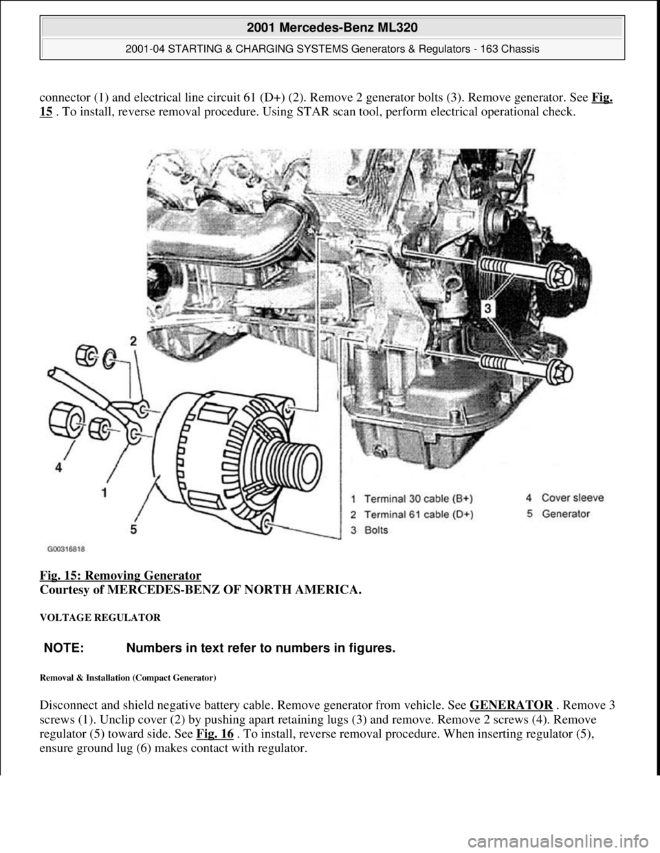
Disconnect and shield negative battery cable. Remove air cleaner housing. Remove engine trim panel. Remove
"V" belt b
y swiveling tensioning pulley and holding in place with a drift. Disconnect generator B+ electrical
NOTE: Numbers in text refer to numbers in figures.
2001 Mercedes-Benz ML320
2001-04 STARTING & CHARGING SYSTEMS Generators & Regulators - 163 Chassis
me
Saturday, October 02, 2010 3:20:32 PMPage 22 © 2006 Mitchell Repair Information Company, LLC.
Page 2057 of 4133
connector (1) and electrical line circuit 61 (D+) (2). Remove 2 generator bolts (3). Remove generator. See Fig.
15 . To install, reverse removal procedure. Using STAR scan tool, perform electrical operational check.
Fig. 15: Removing Generator
Courtesy of MERCEDES-BENZ OF NORTH AMERICA.
VOLTAGE REGULATOR
Removal & Installation (Compact Generator)
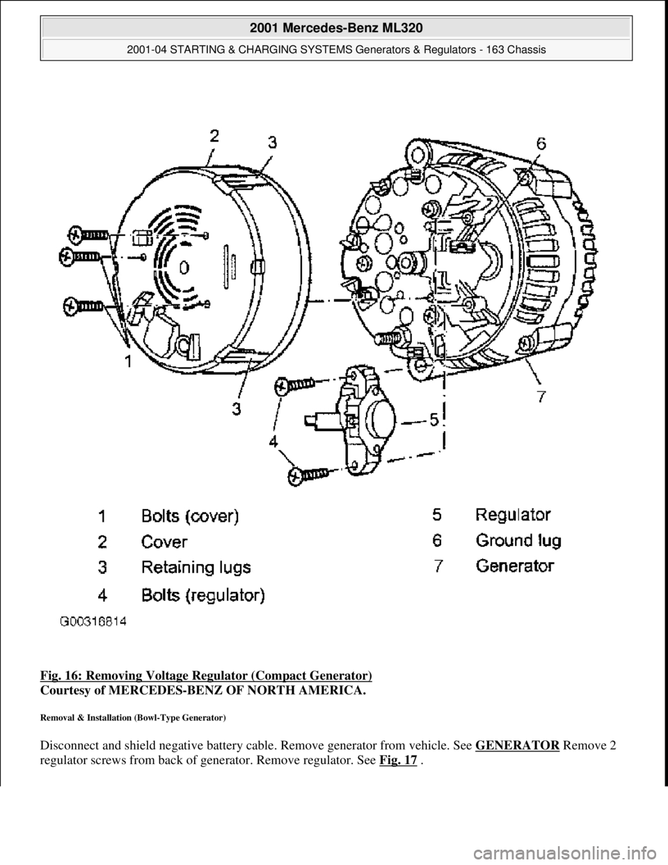
Disconnect and shield negative battery cable. Remove generator from vehicle. See GENERATOR . Remove 3
screws (1). Unclip cover (2) by pushing apart retaining lugs (3) and remove. Remove 2 screws (4). Remove
regulator (5) toward side. See Fig. 16
. To install, reverse removal procedure. When inserting regulator (5),
ensure
ground lug (6) makes contact with regulator.
NOTE: Numbers in text refer to numbers in figures.
2001 Mercedes-Benz ML320
2001-04 STARTING & CHARGING SYSTEMS Generators & Regulators - 163 Chassis
me
Saturday, October 02, 2010 3:20:32 PMPage 23 © 2006 Mitchell Repair Information Company, LLC.
Page 2058 of 4133
Fig. 16: Removing Voltage Re gulator (Compact Generator)
Courtesy of MERCEDES-BENZ OF NORTH AMERICA.
Removal & Installation (Bowl-Type Generator)
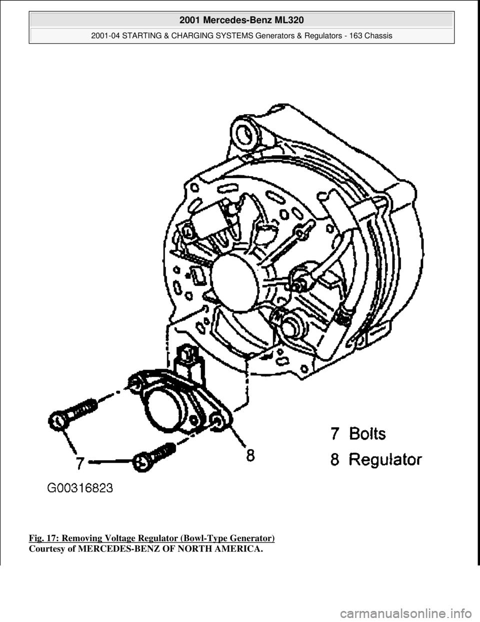
Disconnect and shield negative battery cable. Remove generator from vehicle. See GENERATOR Remove 2
re
gulator screws from back of generator. Remove regulator. See Fig. 17.
2001 Mercedes-Benz ML320
2001-04 STARTING & CHARGING SYSTEMS Gene rators & Regulators - 163 Chassis
me
Saturday, October 02, 2010 3:20:32 PMPage 24 © 2006 Mitchell Repair Information Company, LLC.
Page 2059 of 4133
Fig. 17: Removing Voltage Regulator (Bowl-Type Generator)
Courtesy of MERCEDES-BENZ OF NORTH AMERICA.
2001 Mercedes-Benz ML320
2001-04 STARTING & CHARGING SYSTEMS Generators & Regulators - 163 Chassis
me
Saturday, October 02, 2010 3:20:32 PMPage 25 © 2006 Mitchell Repair Information Company, LLC.
Page 2060 of 4133
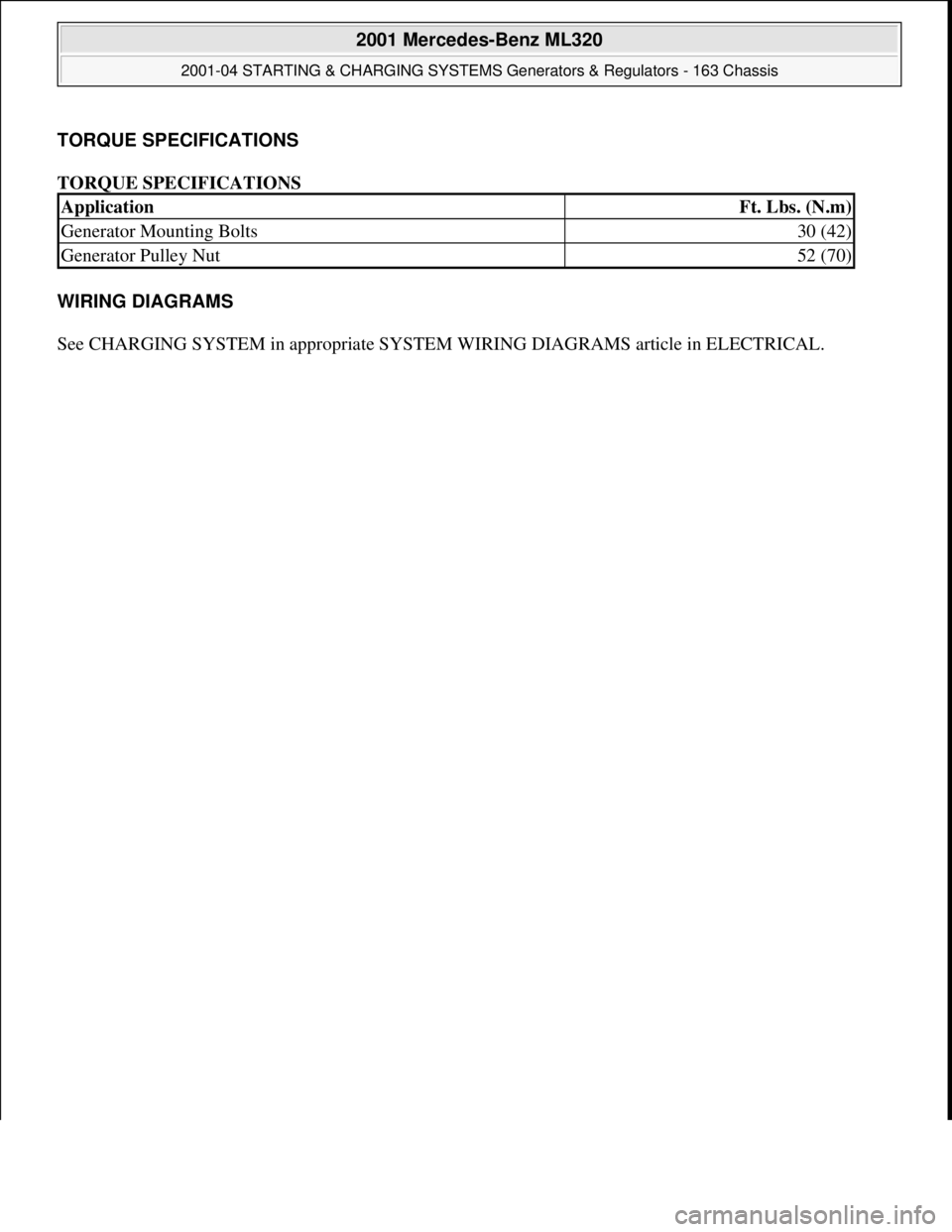
TORQUE SPECIFICATIONS
TORQUE SPECIFICATIONS
WIRING DIAGRAMS
See CHARGING SYSTEM in appropriate SYSTEM WIRING DIAGRAMS article in ELECTRICAL.
ApplicationFt. Lbs. (N.m)
Generator Mounting Bolts30 (42)
Generator Pulley Nut52 (70)
2001 Mercedes-Benz ML320
2001-04 STARTING & CHARGING SYSTEMS Generators & Regulators - 163 Chassis
me
Saturday, October 02, 2010 3:20:32 PMPage 26 © 2006 Mitchell Repair Information Company, LLC.
Trending: check engine light, fuse box, audio, spark plugs replace, compression ratio, child lock, turn signal
