MERCEDES-BENZ ML350 1997 Complete Repair Manual
Manufacturer: MERCEDES-BENZ, Model Year: 1997, Model line: ML350, Model: MERCEDES-BENZ ML350 1997Pages: 4133, PDF Size: 88.89 MB
Page 2151 of 4133
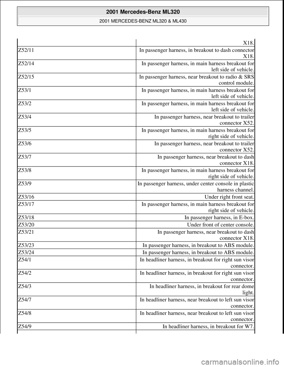
X18.
Z52/11In passenger harness, in breakout to dash connector
X18.
Z52/14In passenger harness, in main harness breakout for
left side of vehicle.
Z52/15In passenger harness, near breakout to radio & SRS
control module.
Z53/1In passenger harness, in main harness breakout for
left side of vehicle.
Z53/2In passenger harness, in main harness breakout for
left side of vehicle.
Z53/4In passenger harness, near breakout to trailer
connector X52.
Z53/5In passenger harness, in main harness breakout for
right side of vehicle.
Z53/6In passenger harness, near breakout to trailer
connector X52.
Z53/7In passenger harness, near breakout to dash
connector X18.
Z53/8In passenger harness, in main harness breakout for
right side of vehicle.
Z53/9In passenger harness, under center console in plastic
harness channel.
Z53/16Under right front seat.
Z53/17In passenger harness, in main harness breakout for
right side of vehicle.
Z53/18In passenger harness, in E-box.
Z53/20Under front of center console.
Z53/21In passenger harness, near breakout to dash
connector X18.
Z53/23In passenger harness, in breakout to ABS module.
Z53/24In passenger harness, in breakout to ABS module.
Z54/1In headliner harness, in breakout for right sun visor
connector.
Z54/2In headliner harness, in breakout for right sun visor
connector.
Z54/3In headliner harness, in breakout for rear dome
light.
Z54/7In headliner harness, near breakout to left sun visor
connector.
Z54/8In headliner harness, near breakout to left sun visor
connector.
Z54/9In headliner harness, in breakout for W7.
2001 Mercedes-Benz ML320
2001 MERCEDES-BENZ ML320 & ML430
me
Saturday, October 02, 2010 3:21:17 PMPage 11 © 2006 Mitchell Repair Information Company, LLC.
Page 2152 of 4133
COMPONENT LOCATION GRAPHICS
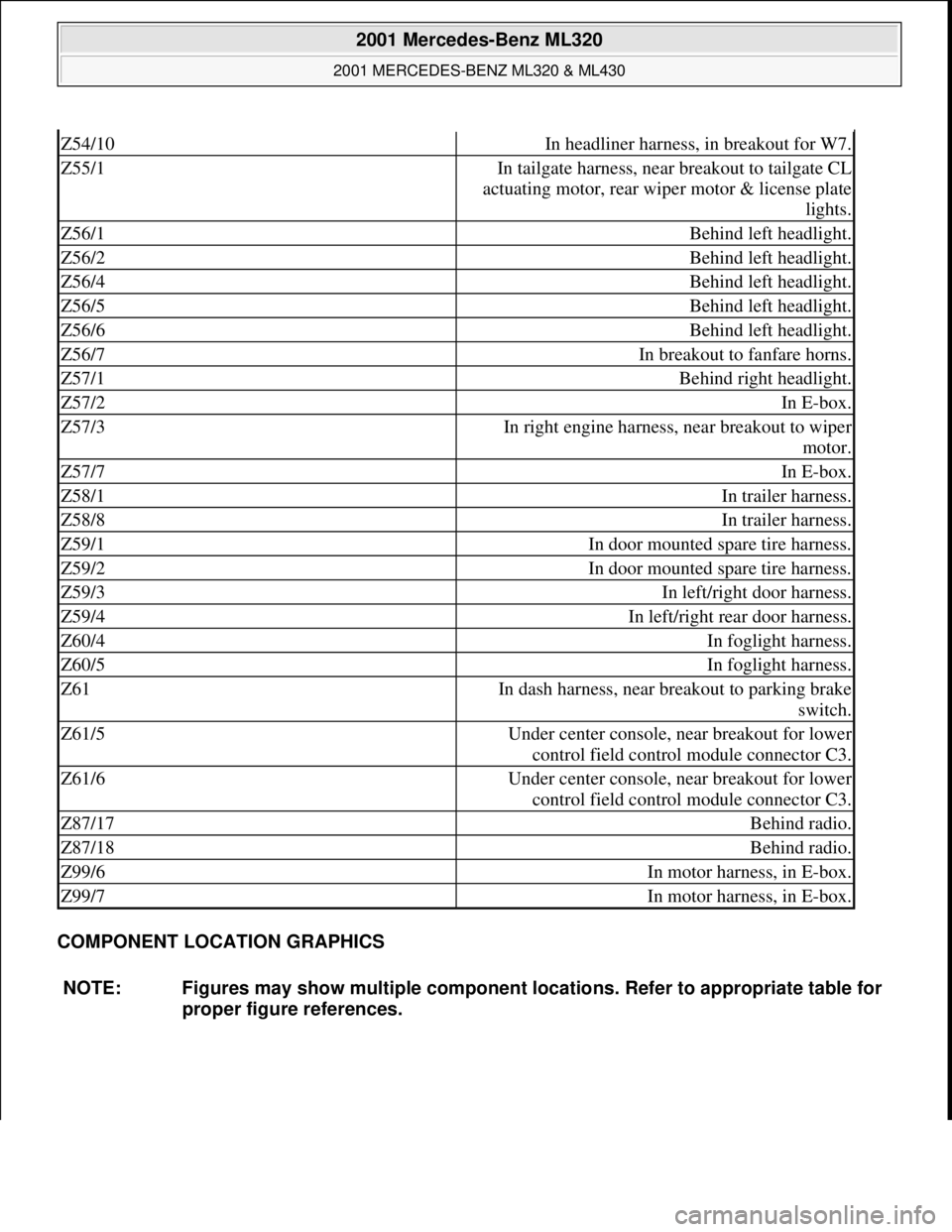
Z54/10In headliner harness, in breakout for W7.
Z55/1In tailgate harness, near breakout to tailgate CL
actuating motor, rear wiper motor & license plate
lights.
Z56/1Behind left headlight.
Z56/2Behind left headlight.
Z56/4Behind left headlight.
Z56/5Behind left headlight.
Z56/6Behind left headlight.
Z56/7In breakout to fanfare horns.
Z57/1Behind right headlight.
Z57/2In E-box.
Z57/3In right engine harness, near breakout to wiper
motor.
Z57/7In E-box.
Z58/1In trailer harness.
Z58/8In trailer harness.
Z59/1In door mounted spare tire harness.
Z59/2In door mounted spare tire harness.
Z59/3In left/right door harness.
Z59/4In left/right rear door harness.
Z60/4In foglight harness.
Z60/5In foglight harness.
Z61In dash harness, near breakout to parking brake
switch.
Z61/5Under center console, near breakout for lower
control field control module connector C3.
Z61/6Under center console, near breakout for lower
control field control module connector C3.
Z87/17Behind radio.
Z87/18Behind radio.
Z99/6In motor harness, in E-box.
Z99/7In motor harness, in E-box.
NOTE: Figures may show multiple component locations. Refer to appropriate table for
proper figure references.
2001 Mercedes-Benz ML320
2001 MERCEDES-BENZ ML320 & ML430
me
Saturday, October 02, 2010 3:21:17 PMPage 12 © 2006 Mitchell Repair Information Company, LLC.
Page 2153 of 4133
2001 Mercedes-Benz ML320
2001 MERCEDES-BENZ ML320 & ML430
me
Saturday, October 02, 2010 3:21:17 PMPage 13 © 2006 Mitchell Repair Information Company, LLC.
Page 2154 of 4133

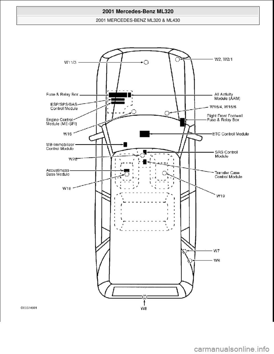
Fig. 1: Plan View Of Vehicle
Courtesy of MERCEDES-BENZ OF NORTH AMERICA.
2001 Mercedes-Benz ML320
2001 MERCEDES-BENZ ML320 & ML430
me
Saturday, October 02, 2010 3:21:17 PMPage 14 © 2006 Mitchell Repair Information Company, LLC.
Page 2155 of 4133
1998-2005 ENGINE
Electrical System - Engine - 163 Chassis
GENERAL INFORMATION
GENERAL NOTES: PASSENGER CARS: ELECTRICAL SYSTEM - ENGINE - AH15.00-Z-9999AZ
MODEL all
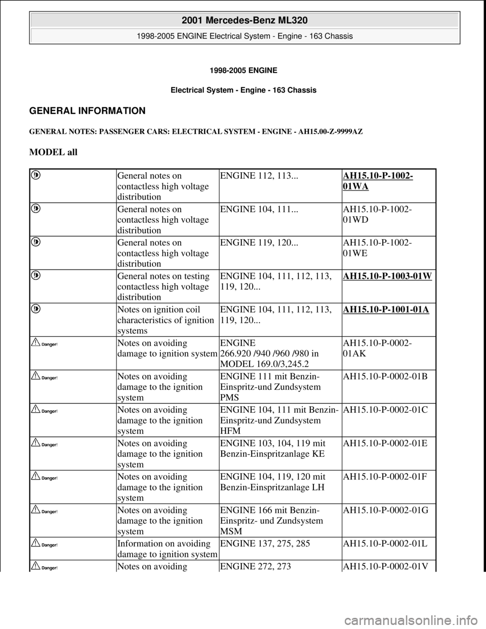
General notes on
contactless high voltage
distributionENGINE 112, 113...AH15.10-P-1002-
01WA
General notes on
contactless high voltage
distributionENGINE 104, 111...AH15.10-P-1002-
01WD
General notes on
contactless high voltage
distributionENGINE 119, 120...AH15.10-P-1002-
01WE
General notes on testing
contactless high voltage
distributionENGINE 104, 111, 112, 113,
119, 120...AH15.10-P-1003-01W
Notes on ignition coil
characteristics of ignition
systemsENGINE 104, 111, 112, 113,
119, 120...AH15.10-P-1001-01A
Notes on avoiding
damage to ignition systemENGINE
266.920 /940 /960 /980 in
MODEL 169.0/3,245.2AH15.10-P-0002-
01AK
Notes on avoiding
damage to the ignition
systemENGINE 111 mit Benzin-
Einspritz-und Zundsystem
PMSAH15.10-P-0002-01B
Notes on avoiding
damage to the ignition
systemENGINE 104, 111 mit Benzin-
Einspritz-und Zundsystem
HFMAH15.10-P-0002-01C
Notes on avoiding
damage to the ignition
systemENGINE 103, 104, 119 mit
Benzin-Einspritzanlage KEAH15.10-P-0002-01E
Notes on avoiding
damage to the ignition
systemENGINE 104, 119, 120 mit
Benzin-Einspritzanlage LHAH15.10-P-0002-01F
Notes on avoiding
damage to the ignition
systemENGINE 166 mit Benzin-
Einspritz- und Zundsystem
MSMAH15.10-P-0002-01G
Information on avoiding
damage to ignition systemENGINE 137, 275, 285AH15.10-P-0002-01L
Notes on avoiding ENGINE 272, 273AH15.10-P-0002-01V
2001 Mercedes-Benz ML320
1998-2005 ENGINE Electrical System - Engine - 163 Chassis
2001 Mercedes-Benz ML320
1998-2005 ENGINE Electrical System - Engine - 163 Chassis
me
Saturday, October 02, 2010 3:18:54 PMPage 1 © 2006 Mitchell Repair Information Company, LLC.
me
Saturday, October 02, 2010 3:18:57 PMPage 1 © 2006 Mitchell Repair Information Company, LLC.
Page 2156 of 4133
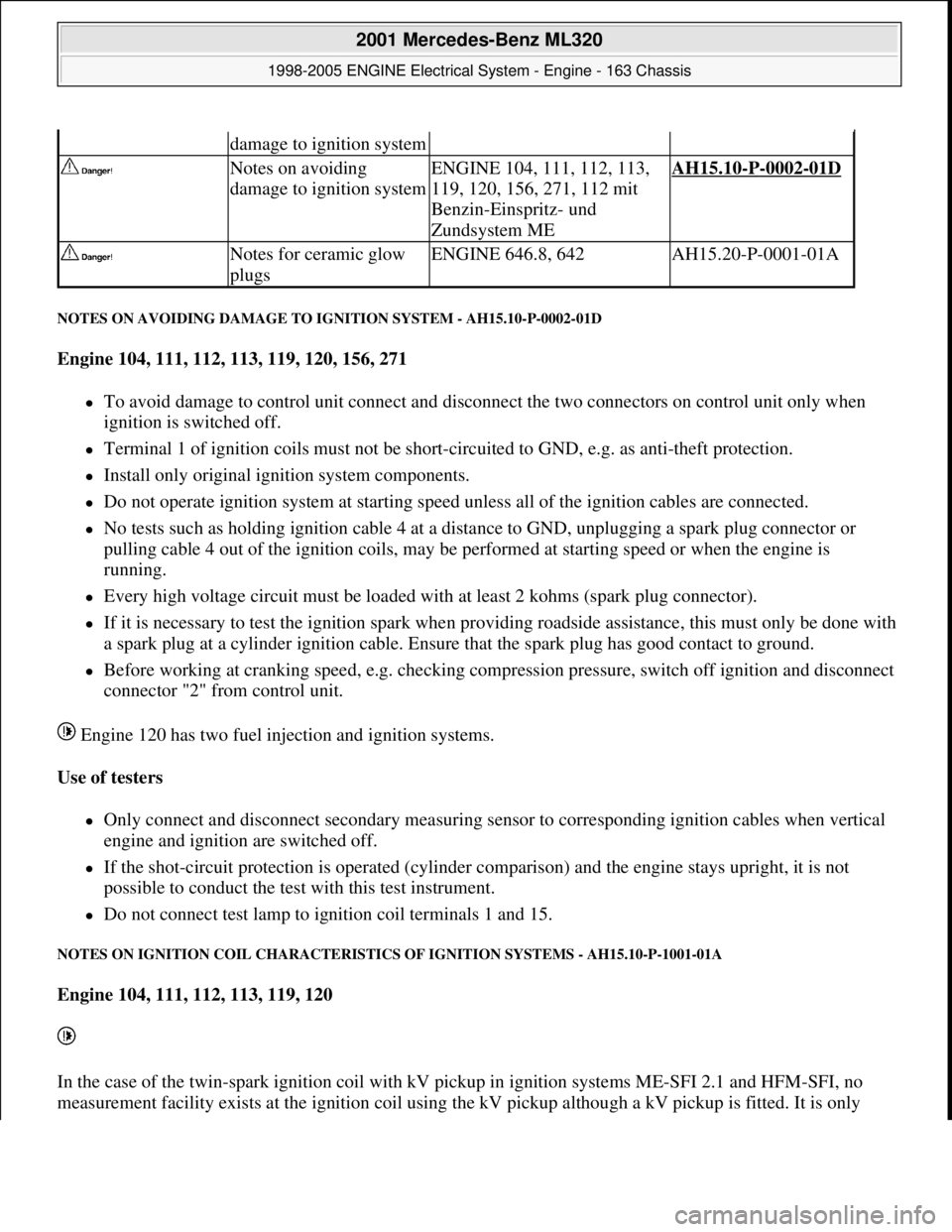
NOTES ON AVOIDING DAMAGE TO IGNITION SYSTEM - AH15.10-P-0002-01D
Engine 104, 111, 112, 113, 119, 120, 156, 271
To avoid damage to control unit connect and disconnect the two connectors on control unit only when
ignition is switched off.
Terminal 1 of ignition coils must not be short-circuited to GND, e.g. as anti-theft protection.
Install only original ignition system components.
Do not operate ignition system at starting speed unless all of the ignition cables are connected.
No tests such as holding ignition cable 4 at a distance to GND, unplugging a spark plug connector or
pulling cable 4 out of the ignition coils, may be performed at starting speed or when the engine is
running.
Every high voltage circuit must be loaded with at least 2 kohms (spark plug connector).
If it is necessary to test the ignition spark when providing roadside assistance, this must only be done with
a spark plug at a cylinder ignition cable. Ensure that the spark plug has good contact to ground.
Before working at cranking speed, e.g. checking compression pressure, switch off ignition and disconnect
connector "2" from control unit.
Engine 120 has two fuel injection and ignition systems.
Use of testers
Only connect and disconnect secondary measuring sensor to corresponding ignition cables when vertical
engine and ignition are switched off.
If the shot-circuit protection is operated (cylinder comparison) and the engine stays upright, it is not
possible to conduct the test with this test instrument.
Do not connect test lamp to ignition coil terminals 1 and 15.
NOTES ON IGNITION COIL CHARACTERISTICS OF IGNITION SYSTEMS - AH15.10-P-1001-01A
Engine 104, 111, 112, 113, 119, 120
In the case of the twin-spark ignition coil with kV pickup in ignition systems ME-SFI 2.1 and HFM-SFI, no
measurement facilit
y exists at the ignition coil using the kV pickup although a kV pickup is fitted. It is only
damage to ignition system
Notes on avoiding
damage to ignition systemENGINE 104, 111, 112, 113,
119, 120, 156, 271, 112 mit
Benzin-Einspritz- und
Zundsystem MEAH15.10-P-0002-01D
Notes for ceramic glow
plugsENGINE 646.8, 642AH15.20-P-0001-01A
2001 Mercedes-Benz ML320
1998-2005 ENGINE Electrical System - Engine - 163 Chassis
me
Saturday, October 02, 2010 3:18:54 PMPage 2 © 2006 Mitchell Repair Information Company, LLC.
Page 2157 of 4133
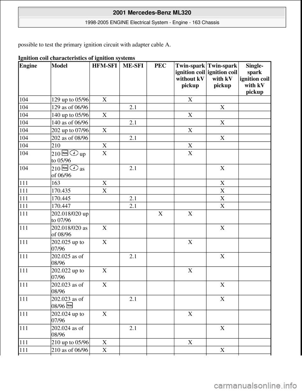
possible to test the primary ignition circuit with adapter cable A.
Ignition coil characteristics of ignition systems
EngineModelHFM-SFIME-SFIPECTwin-spark
i
gnition coil
without kV
pickup
Twin-spark
i
gnition coil
with kV
pickup
Single-
spark
i
gnition coil
with kV
pickup
104129 up to 05/96X X
104129 as of 06/96 2.1 X
104140 up to 05/96X X
104140 as of 06/96 2.1 X
104202 up to 07/96X X
104202 as of 08/96 2.1 X
104210X X
104210 up
to 05/96X X
104210 as
of 06/96 2.1 X
111163X X
111170.435X X
111170.445 2.1 X
111170.447 2.1 X
111202.018/020 up
to 07/96 XX
111202.018/020 as
of 08/96X X
111202.025 up to
07/96X X
111202.025 as of
08/96 2.1 X
111202.022 up to
07/96X X
111202.023 as of
08/96X X
111202.023 as of
08/96 2.1 X
111202.024 up to
07/96X X
111202.024 as of
08/96 2.1 X
111210 up to 05/96X X
111210 as of 06/96X X
2001 Mercedes-Benz ML320
1998-2005 ENGINE Electrical System - Engine - 163 Chassis
me
Saturday, October 02, 2010 3:18:54 PMPage 3 © 2006 Mitchell Repair Information Company, LLC.
Page 2158 of 4133
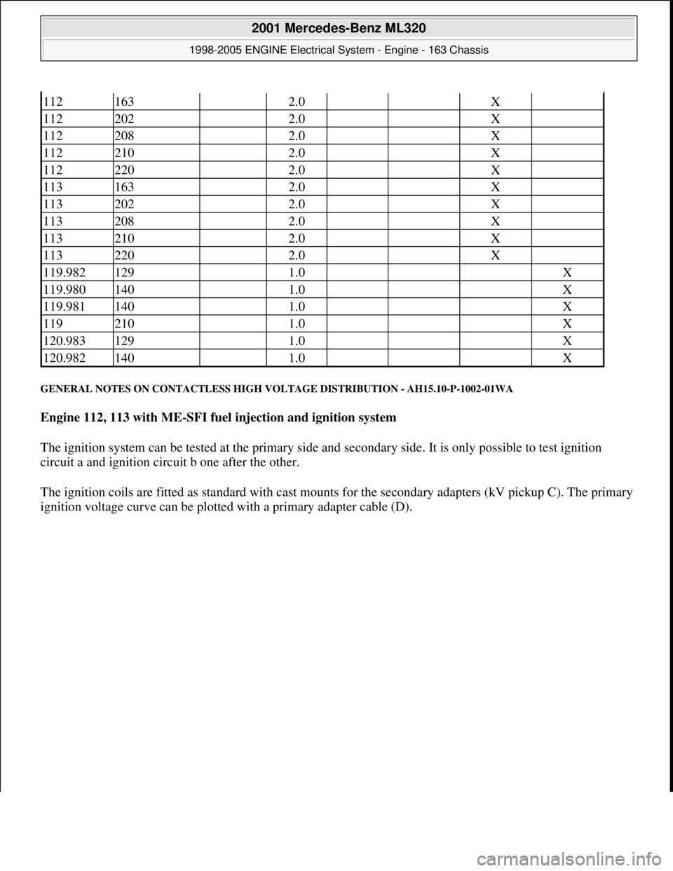
GENERAL NOTES ON CONTACTLESS HIGH VOLTAGE DISTRIBUTION - AH15.10-P-1002-01WA
Engine 112, 113 with ME-SFI fuel injection and ignition system
The ignition system can be tested at the primary side and secondary side. It is only possible to test ignition
circuit a and ignition circuit b one after the other.
The ignition coils are fitted as standard with cast mounts for the secondary adapters (kV pickup C). The primary
i
gnition voltage curve can be plotted with a primary adapter cable (D).
112163 2.0 X
112202 2.0 X
112208 2.0 X
112210 2.0 X
112220 2.0 X
113163 2.0 X
113202 2.0 X
113208 2.0 X
113210 2.0 X
113220 2.0 X
119.982129 1.0 X
119.980140 1.0 X
119.981140 1.0 X
119210 1.0 X
120.983129 1.0 X
120.982140 1.0 X
2001 Mercedes-Benz ML320
1998-2005 ENGINE Electrical System - Engine - 163 Chassis
me
Saturday, October 02, 2010 3:18:54 PMPage 4 © 2006 Mitchell Repair Information Company, LLC.
Page 2159 of 4133
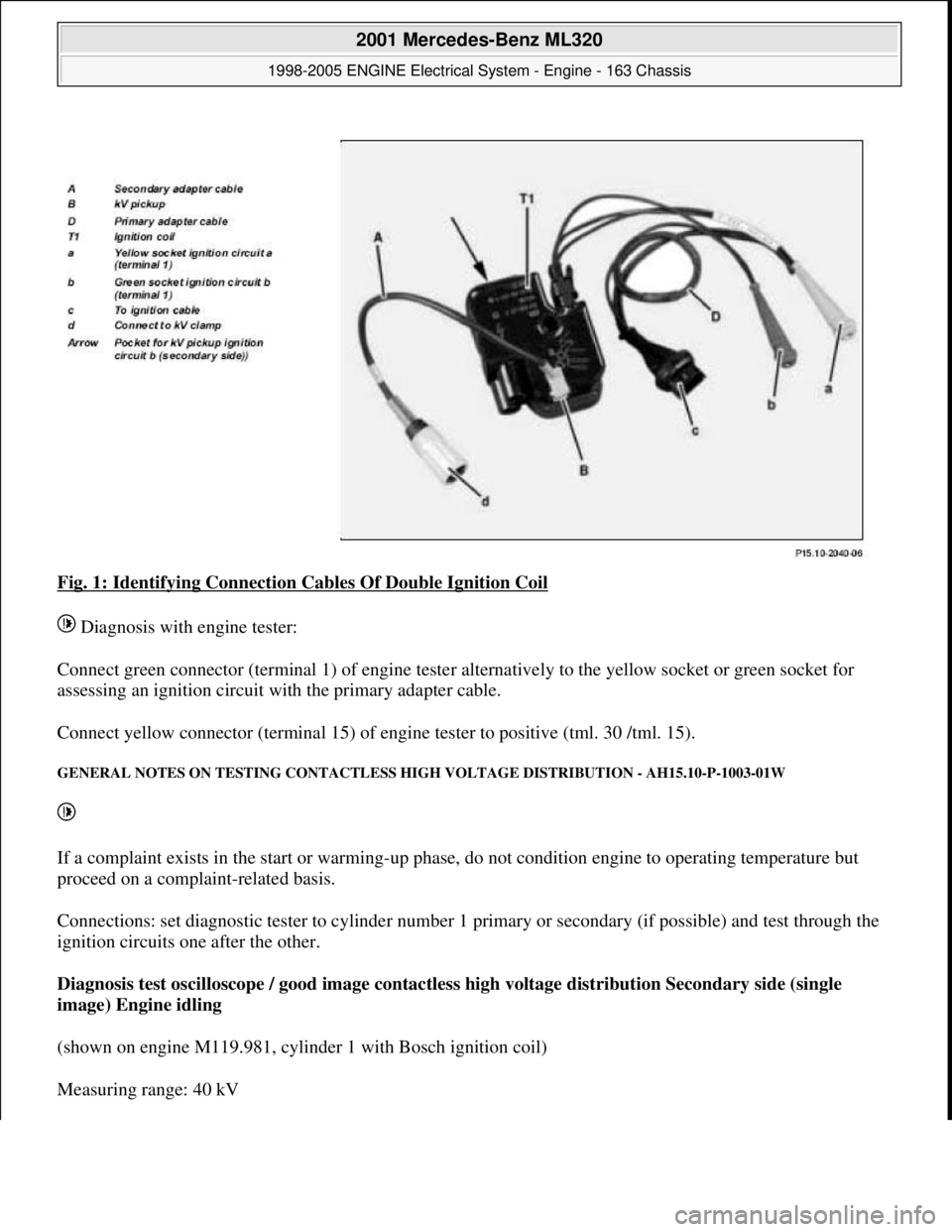
Fig. 1: Identifying Connection Cables Of Double Ignition Coil
Diagnosis with engine tester:
Connect green connector (terminal 1) of engine tester alternatively to the yellow socket or green socket for
assessing an ignition circuit with the primary adapter cable.
Connect yellow connector (terminal 15) of engine tester to positive (tml. 30 /tml. 15).
GENERAL NOTES ON TESTING CONTACTLESS HIGH VOLTAGE DISTRIBUTION - AH15.10-P-1003-01W
If a complaint exists in the start or warming-up phase, do not condition engine to operating temperature but
proceed on a complaint-related basis.
Connections: set diagnostic tester to cylinder number 1 primary or secondary (if possible) and test through the
ignition circuits one after the other.
Diagnosis test oscilloscope / good image contactless high voltage distribution Secondary side (single
image) Engine idling
(shown on engine M119.981, cylinder 1 with Bosch ignition coil)
Measurin
g range: 40 kV
2001 Mercedes-Benz ML320
1998-2005 ENGINE Electrical System - Engine - 163 Chassis
me
Saturday, October 02, 2010 3:18:54 PMPage 5 © 2006 Mitchell Repair Information Company, LLC.
Page 2160 of 4133
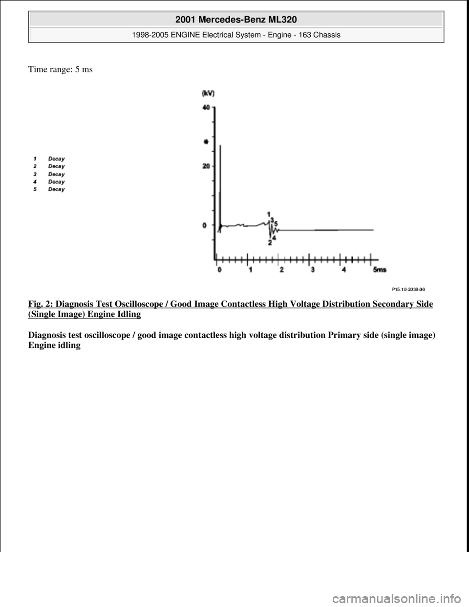
Time range: 5 ms
Fig. 2: Diagnosis Test Oscilloscope / Good Image Contactless High Voltage Distribution Secondary Side
(Single Image) Engine Idling
Diagnosis test oscilloscope / good image contactless high voltage distribution Primary side (single image)
Engine idling
2001 Mercedes-Benz ML320
1998-2005 ENGINE Electrical System - Engine - 163 Chassis
me
Saturday, October 02, 2010 3:18:54 PMPage 6 © 2006 Mitchell Repair Information Company, LLC.