park MERCEDES-BENZ ML350 1997 Complete Repair Manual
[x] Cancel search | Manufacturer: MERCEDES-BENZ, Model Year: 1997, Model line: ML350, Model: MERCEDES-BENZ ML350 1997Pages: 4133, PDF Size: 88.89 MB
Page 1991 of 4133
AR54.65-P-0002GH
Remove/install Parktronic system (PTS) sensors in rear bumper
19.4.01
MODEL
163.113 /128 /154 /157 /174 /175 with CODE (220a) Parktronic System (PTS)
P54.65-2412-06
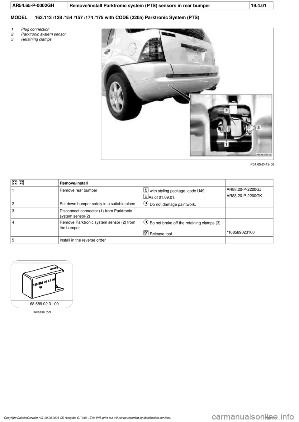
1
Plug connection
2
Parktronic system sensor
3
Retaining clamps
Remove/install
1
Remove rear bumper
with styling package, code U49.
AR88.20-P-2200GJ
As of 01.09.01.
AR88.20-P-2200GK
2
Put down bumper safely in a suitable place
Do not damage paintwork.
3
Disconnect connector (1) from Parktronic
system sensor(2)
4
Remove Parktronic system sensor (2) from
the bumper
Bo not brake off the retaining clamps (3).
Release tool
*168589023100
5
Install in the reverse order
Release tool
168 589 02 31 00
Copyright DaimlerChrysler AG 20.05.2006 CD-Ausgabe G/10/04 . This WIS print-out will not be recorde
d by Modification services.
Page 1
Page 1992 of 4133
AR88.20-P-2200GJ
Remove/install rear bumper
6.4.99
MODEL
163.113 /128 /136 /154 /157 /172 /175 with CODE (U49) Styling package
MODEL
163.174
P88.20-2090-09
Remove/install
1.1
Separate antenna of emergency call system
E-Call connector
Only with E-call emergency call system,
code 349. The connector is located behind
the side flap of the right C-pillar paneling at
the jack socket point.
2
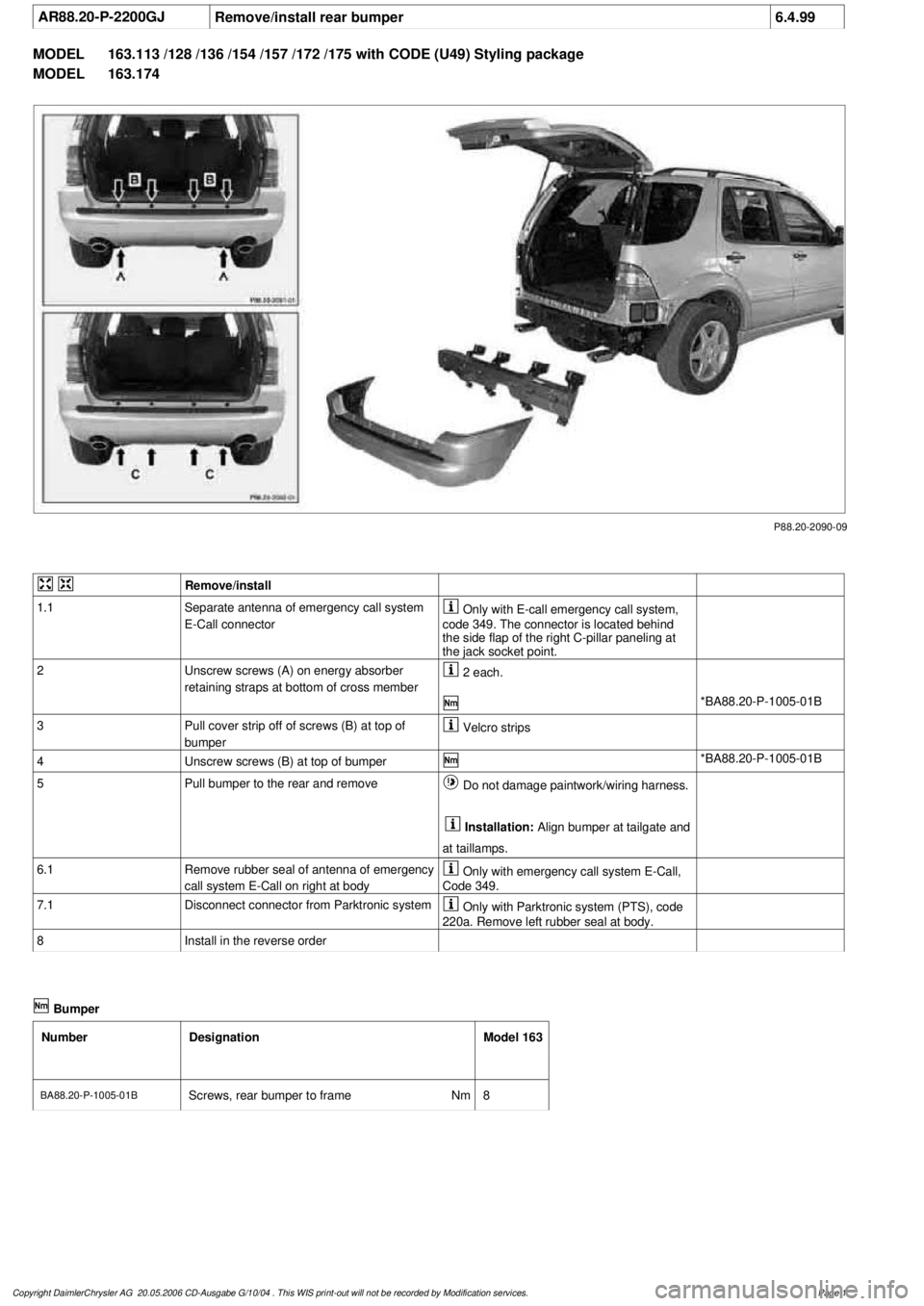
Unscrew screws (A) on energy absorber
retaining straps at bottom of cross member
2 each.
*BA88.20-P-1005-01B
3
Pull cover strip off of screws (B) at top of
bumper
Velcro strips
4
Unscrew screws (B) at top of bumper
*BA88.20-P-1005-01B
5
Pull bumper to the rear and remove
Do not damage paintwork/wiring harness.
Installation:
Align bumper at tailgate and
at taillamps.
6.1
Remove rubber seal of antenna of emergency
call system E-Call on right at body
Only with emergency call system E-Call,
Code 349.
7.1
Disconnect connector from Parktronic system
Only with Parktronic system (PTS), code
220a. Remove left rubber seal at body.
8
Install in the reverse order
Bumper
Number
Designation
Model 163
BA88.20-P-1005-01B
Screws, rear bumper to frame
Nm
8
Copyright DaimlerChrysler AG 20.05.2006 CD-Ausgabe G/10/04 . This WIS print-out will not be recorde
d by Modification services.
Page 1
Page 1993 of 4133
AR88.20-P-2200GJ
Remove/install rear bumper
6.4.99
MODEL
163.113 /128 /136 /154 /157 /172 /175 with CODE (U49) Styling package
MODEL
163.174
P88.20-2090-09
Remove/install
1.1
Separate antenna of emergency call system
E-Call connector
Only with E-call emergency call system,
code 349. The connector is located behind
the side flap of the right C-pillar paneling at
the jack socket point.
2
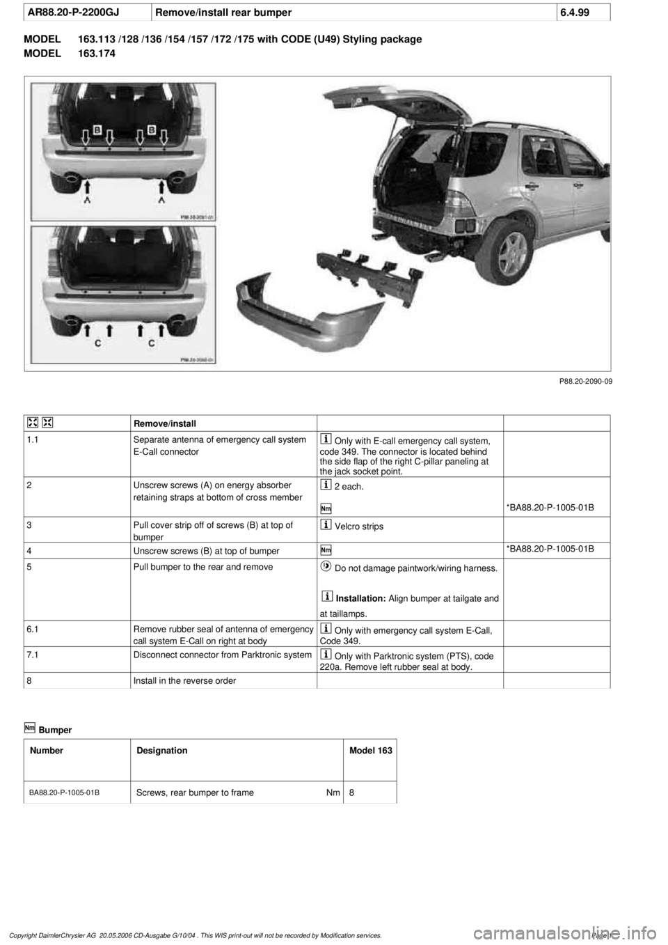
Unscrew screws (A) on energy absorber
retaining straps at bottom of cross member
2 each.
*BA88.20-P-1005-01B
3
Pull cover strip off of screws (B) at top of
bumper
Velcro strips
4
Unscrew screws (B) at top of bumper
*BA88.20-P-1005-01B
5
Pull bumper to the rear and remove
Do not damage paintwork/wiring harness.
Installation:
Align bumper at tailgate and
at taillamps.
6.1
Remove rubber seal of antenna of emergency
call system E-Call on right at body
Only with emergency call system E-Call,
Code 349.
7.1
Disconnect connector from Parktronic system
Only with Parktronic system (PTS), code
220a. Remove left rubber seal at body.
8
Install in the reverse order
Bumper
Number
Designation
Model 163
BA88.20-P-1005-01B
Screws, rear bumper to frame
Nm
8
Copyright DaimlerChrysler AG 20.05.2006 CD-Ausgabe G/10/04 . This WIS print-out will not be recorde
d by Modification services.
Page 1
Page 1996 of 4133
AR88.20-P-2000GJ
Remove/install front bumper
26.2.01
MODEL
163.113 /154 #A as of 289565,
163.113 #X as of 754620,
163.128 /154 /157 /175 except CODE (U49) Styling package
P88.20-2203-09
Remove/install
1.1
Remove brush guard together with underride
guard
If installed.
AR88.30-P-2000-01GI
*BA88.30-P-1003-01A
*BA88.30-P-1015-01A
*BA88.30-P-1016-01A
2
Remove fog lamps
AR82.10-P-5103GI
3
Remove front bumper grille.
Carefully remove bumper grille so that
bumper grille and mounts cannot be damaged.
Remove with correspondingly formed hook.
Pulling hook
*140589023300
4
Remove outdoor temperature sensor from
bumper.
5
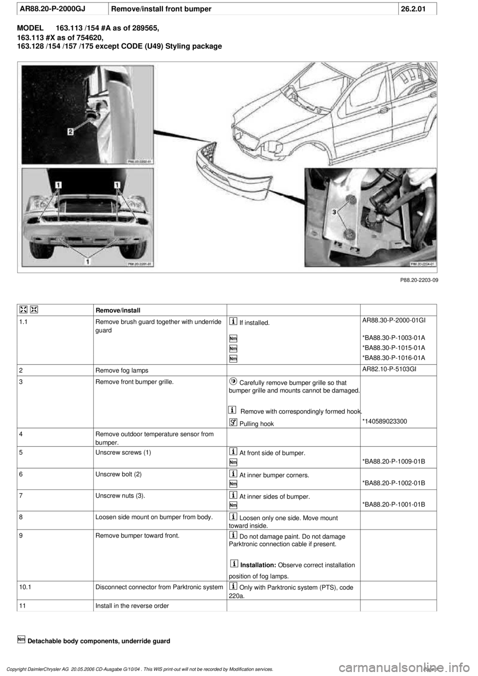
Unscrew screws (1)
At front side of bumper.
*BA88.20-P-1009-01B
6
Unscrew bolt (2)
At inner bumper corners.
*BA88.20-P-1002-01B
7
Unscrew nuts (3).
At inner sides of bumper.
*BA88.20-P-1001-01B
8
Loosen side mount on bumper from body.
Loosen only one side. Move mount
toward inside.
9
Remove bumper toward front.
Do not damage paint. Do not damage
Parktronic connection cable if present.
Installation:
Observe correct installation
position of fog lamps.
10.1
Disconnect connector from Parktronic system
Only with Parktronic system (PTS), code
220a.
11
Install in the reverse order
Detachable body components, underride guard
Copyright DaimlerChrysler AG 20.05.2006 CD-Ausgabe G/10/04 . This WIS print-out will not be recorde
d by Modification services.
Page 1
Page 1998 of 4133
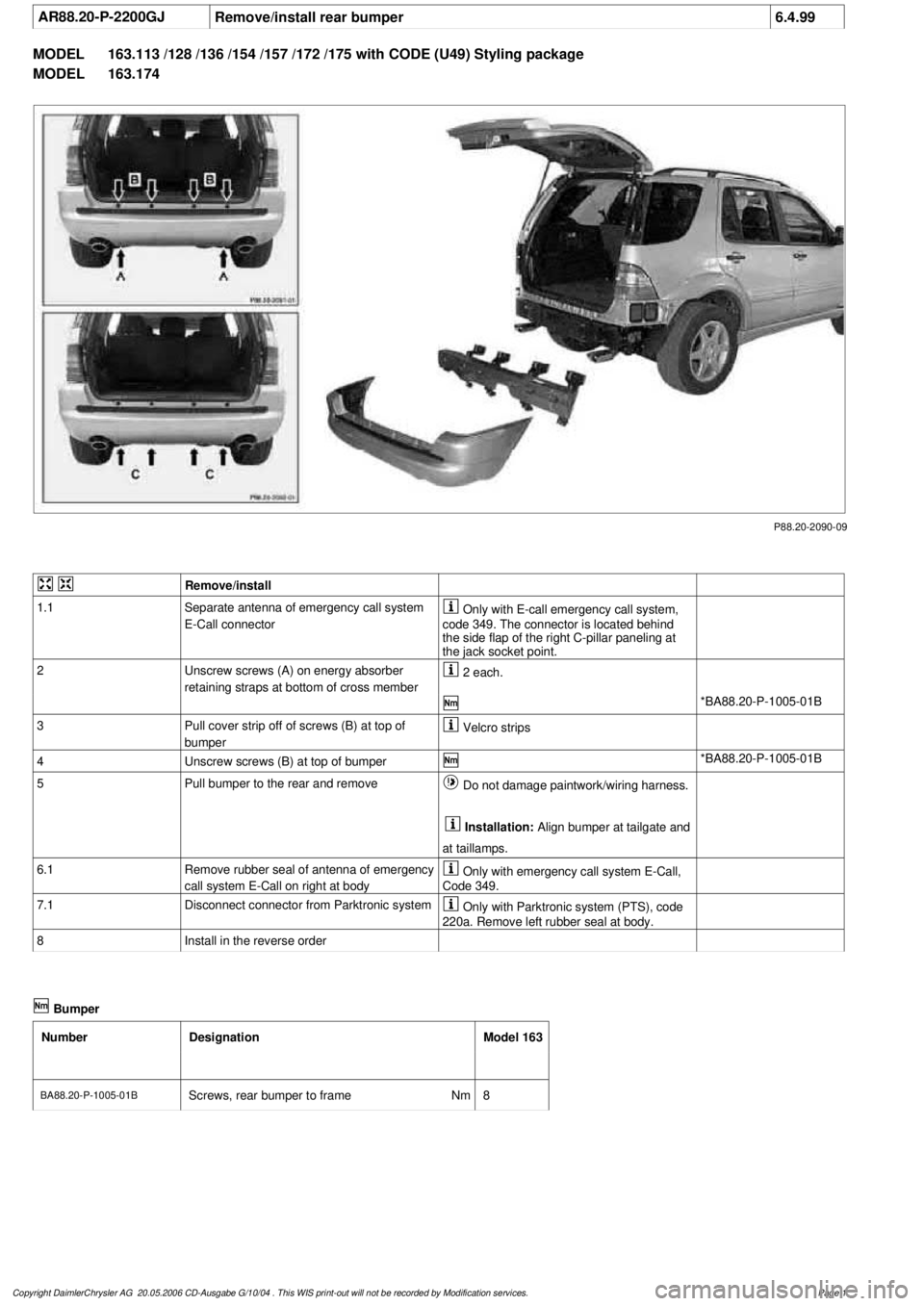
AR88.20-P-2200GJ
Remove/install rear bumper
6.4.99
MODEL
163.113 /128 /136 /154 /157 /172 /175 with CODE (U49) Styling package
MODEL
163.174
P88.20-2090-09
Remove/install
1.1
Separate antenna of emergency call system
E-Call connector
Only with E-call emergency call system,
code 349. The connector is located behind
the side flap of the right C-pillar paneling at
the jack socket point.
2
Unscrew screws (A) on energy absorber
retaining straps at bottom of cross member
2 each.
*BA88.20-P-1005-01B
3
Pull cover strip off of screws (B) at top of
bumper
Velcro strips
4
Unscrew screws (B) at top of bumper
*BA88.20-P-1005-01B
5
Pull bumper to the rear and remove
Do not damage paintwork/wiring harness.
Installation:
Align bumper at tailgate and
at taillamps.
6.1
Remove rubber seal of antenna of emergency
call system E-Call on right at body
Only with emergency call system E-Call,
Code 349.
7.1
Disconnect connector from Parktronic system
Only with Parktronic system (PTS), code
220a. Remove left rubber seal at body.
8
Install in the reverse order
Bumper
Number
Designation
Model 163
BA88.20-P-1005-01B
Screws, rear bumper to frame
Nm
8
Copyright DaimlerChrysler AG 20.05.2006 CD-Ausgabe G/10/04 . This WIS print-out will not be recorde
d by Modification services.
Page 1
Page 2003 of 4133
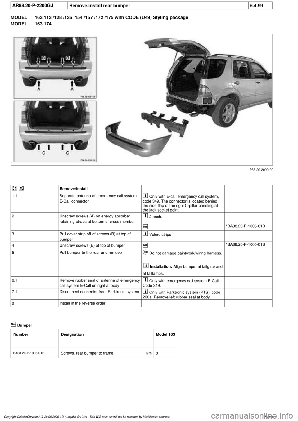
AR88.20-P-2200GJ
Remove/install rear bumper
6.4.99
MODEL
163.113 /128 /136 /154 /157 /172 /175 with CODE (U49) Styling package
MODEL
163.174
P88.20-2090-09
Remove/install
1.1
Separate antenna of emergency call system
E-Call connector
Only with E-call emergency call system,
code 349. The connector is located behind
the side flap of the right C-pillar paneling at
the jack socket point.
2
Unscrew screws (A) on energy absorber
retaining straps at bottom of cross member
2 each.
*BA88.20-P-1005-01B
3
Pull cover strip off of screws (B) at top of
bumper
Velcro strips
4
Unscrew screws (B) at top of bumper
*BA88.20-P-1005-01B
5
Pull bumper to the rear and remove
Do not damage paintwork/wiring harness.
Installation:
Align bumper at tailgate and
at taillamps.
6.1
Remove rubber seal of antenna of emergency
call system E-Call on right at body
Only with emergency call system E-Call,
Code 349.
7.1
Disconnect connector from Parktronic system
Only with Parktronic system (PTS), code
220a. Remove left rubber seal at body.
8
Install in the reverse order
Bumper
Number
Designation
Model 163
BA88.20-P-1005-01B
Screws, rear bumper to frame
Nm
8
Copyright DaimlerChrysler AG 20.05.2006 CD-Ausgabe G/10/04 . This WIS print-out will not be recorde
d by Modification services.
Page 1
Page 2004 of 4133
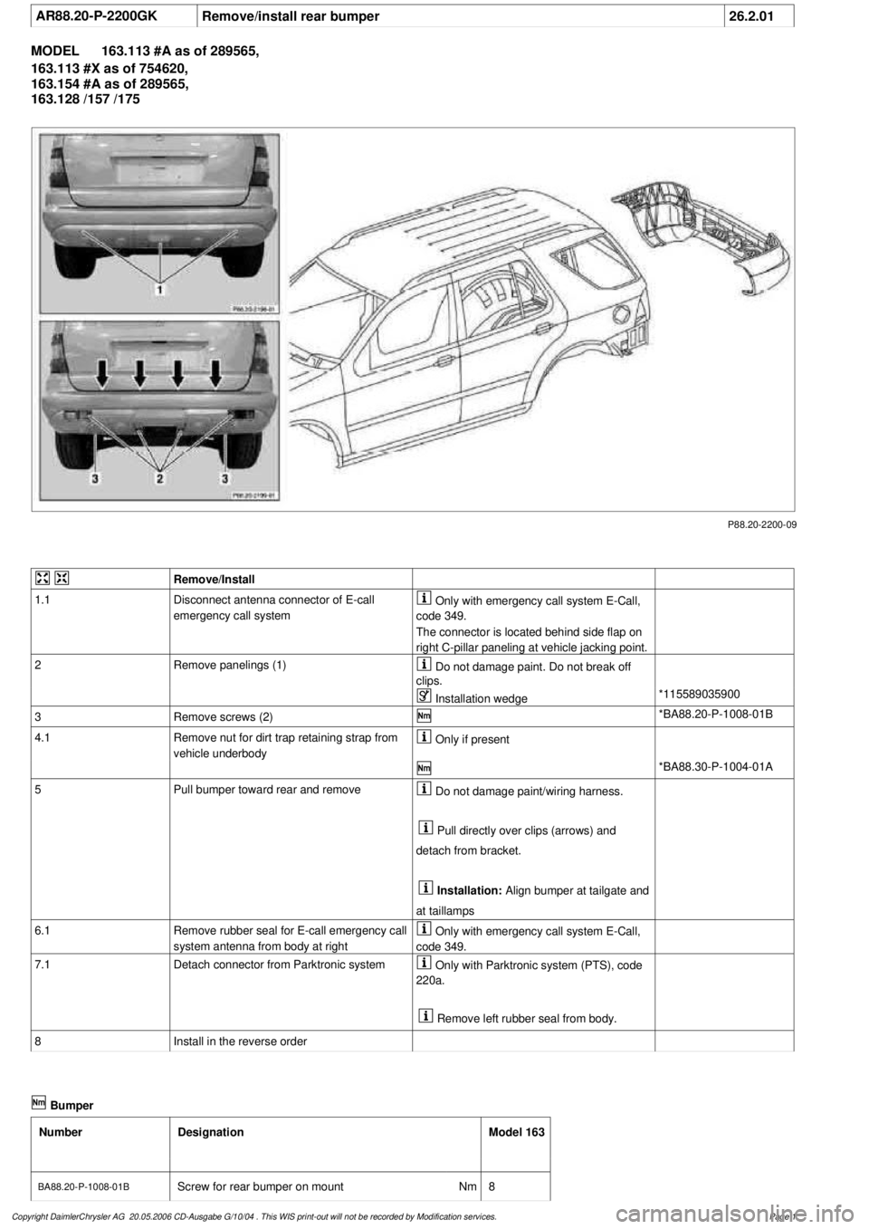
AR88.20-P-2200GK
Remove/install rear bumper
26.2.01
MODEL
163.113 #A as of 289565,
163.113 #X as of 754620,
163.154 #A as of 289565,
163.128 /157 /175
P88.20-2200-09
Remove/Install
1.1
Disconnect antenna connector of E-call
emergency call system
Only with emergency call system E-Call,
code 349.
The connector is located behind side flap on
right C-pillar paneling at vehicle jacking point.
2
Remove panelings (1)
Do not damage paint. Do not break off
clips.
Installation wedge
*115589035900
3
Remove screws (2)
*BA88.20-P-1008-01B
4.1
Remove nut for dirt trap retaining strap from
vehicle underbody
Only if present
*BA88.30-P-1004-01A
5
Pull bumper toward rear and remove
Do not damage paint/wiring harness.
Pull directly over clips (arrows) and
detach from bracket.
Installation:
Align bumper at tailgate and
at taillamps
6.1
Remove rubber seal for E-call emergency call
system antenna from body at right
Only with emergency call system E-Call,
code 349.
7.1
Detach connector from Parktronic system
Only with Parktronic system (PTS), code
220a.
Remove left rubber seal from body.
8
Install in the reverse order
Bumper
Number
Designation
Model 163
BA88.20-P-1008-01B
Screw for rear bumper on mount
Nm
8
Copyright DaimlerChrysler AG 20.05.2006 CD-Ausgabe G/10/04 . This WIS print-out will not be recorde
d by Modification services.
Page 1
Page 2065 of 4133

SI54.50-P-0001A
Service Information: Compass in trip computer
22.10.00
MODELS
163.113 /154 /172 as of 1.9.00,
163.128 /157 /174 /175 with CODE (245) Trip computer
The compass is calibrated in the factory in order to compensate
for deviations caused by magnetic field intensity of the vehicle and
magnetic interference when operating the heated rear window.
Once the compass is calibrated, it never needs to be recalibrated
under normal operating conditions. If a strong deviation in magnetic
field intensity is detected, the compass automatically recalibrates
itself.
A calibration must be carried out if the compass is replaced.
Additionally, the user can fine tune the compass in order to adapt
it to the vehicle's surrounding area. By setting the respective
compass zone, the compass compensates for deviations in the
earth's magnetic field.
The calibration should take place at least 10 m from any source of
interference such as power lines, buildings and parked vehicles.
Zone setting
1
Press the MODE button on the trip computer
until the compass direction is displayed
2
Press the RESET button once
The current compass zone is displayed
3
Press the RESET button until the desired
compass zone is displayed
The maps for determining the correct
compass zone can be found in the owner's
manual. If the RESET button is not pressed
within 5 seconds, the point of the compass is
displayed again.
Compass calibration
4
Bring the compass to the compass zone
display mode
5
Press the MODE button once
Display shows
CAL-
on.
6
Press the RESET button for at least 2 seconds
The hyphen (
-
) in the display disappears.
The calibration mode is active and remains
active until the calibration process has
concluded. If the ignition is switched off and
on, calibration mode remains active, even if
CAL
no longer is displayed.
7
Drive two complete circles at a speed of
between 5 - 10 km/h
Heated rear window switched off.
8
Switch heated rear window on
9
Drive three full circles at a speed from 5 - 10
km/h.
Calibration process concluded.
Although the display can change from
CAL
to
the point of the compass before the
calibration drive has been concluded, the
calibration process is still active and must be
carried out exactly as described.
Copyright DaimlerChrysler AG 18.05.2006 CD-Ausgabe G/10/04 . This WIS print-out will not be recorde
d by Modification services.
Page 1
Page 2086 of 4133
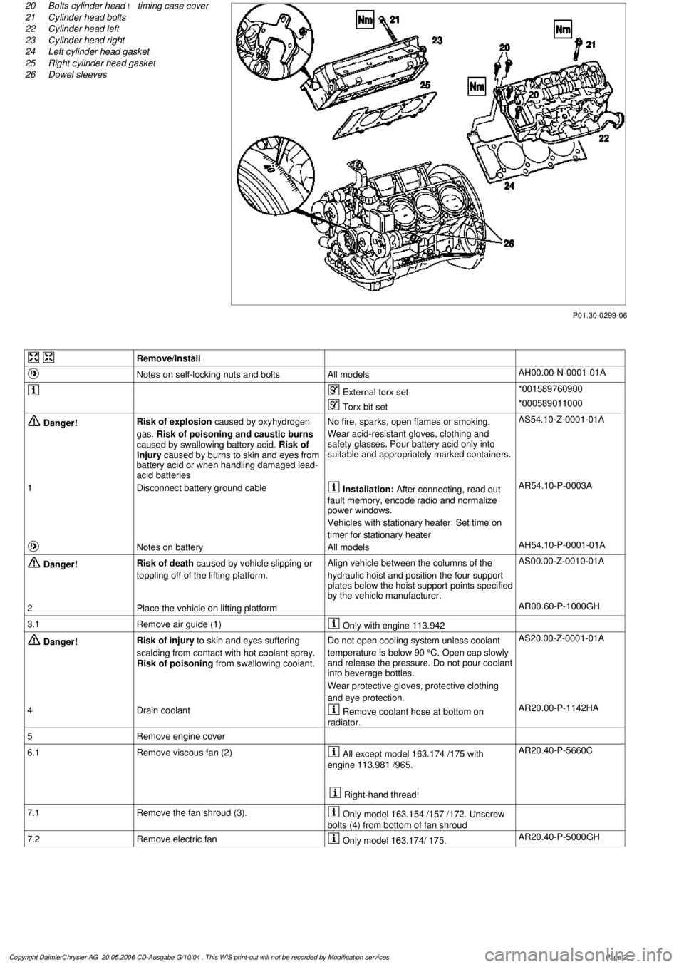
P01.30-0299-06
20
Bolts cylinder head
!
timing case cover
21
Cylinder head bolts
22
Cylinder head left
23
Cylinder head right
24
Left cylinder head gasket
25
Right cylinder head gasket
26
Dowel sleeves
Remove/Install
Notes on self-locking nuts and bolts
All models
AH00.00-N-0001-01A
External torx set
*001589760900
Torx bit set
*000589011000
Danger!
Risk of explosion
caused by oxyhydrogen
gas.
Risk of poisoning and caustic burns
caused by swallowing battery acid.
Risk of
injury caused by burns to skin and eyes from
battery acid or when handling damaged lead-
acid batteries
No fire, sparks, open flames or smoking.
Wear acid-resistant gloves, clothing and
safety glasses. Pour battery acid only into
suitable and appropriately marked containers.
AS54.10-Z-0001-01A
1
Disconnect battery ground cable
Installation:
After connecting, read out
fault memory, encode radio and normalize
power windows.
Vehicles with stationary heater: Set time on
timer for stationary heater
AR54.10-P-0003A
Notes on battery
All models
AH54.10-P-0001-01A
Danger!
Risk of death
caused by vehicle slipping or
toppling off of the lifting platform.
Align vehicle between the columns of the
hydraulic hoist and position the four support
plates below the hoist support points specified
by the vehicle manufacturer.
AS00.00-Z-0010-01A
2
Place the vehicle on lifting platform
AR00.60-P-1000GH
3.1
Remove air guide (1)
Only with engine 113.942
Danger!
Risk of injury
to skin and eyes suffering
scalding from contact with hot coolant spray.
Risk of poisoning
from swallowing coolant.
Do not open cooling system unless coolant
temperature is below 90 °C. Open cap slowly
and release the pressure. Do not pour coolant
into beverage bottles.
Wear protective gloves, protective clothing
and eye protection.
AS20.00-Z-0001-01A
4
Drain coolant
Remove coolant hose at bottom on
radiator.
AR20.00-P-1142HA
5
Remove engine cover
6.1
Remove viscous fan (2)
All except model 163.174 /175 with
engine 113.981 /965.
Right-hand thread!
AR20.40-P-5660C
7.1
Remove the fan shroud (3).
Only model 163.154 /157 /172. Unscrew
bolts (4) from bottom of fan shroud
7.2
Remove electric fan
Only model 163.174/ 175.
AR20.40-P-5000GH
Copyright DaimlerChrysler AG 20.05.2006 CD-Ausgabe G/10/04 . This WIS print-out will not be recorde
d by Modification services.
Page 2
Page 2087 of 4133

8
Attach guard plate for radiator/condenser
y
Guard plate for radiator/condenser
Engine 606 in model 124,
Engine 606.961 in model 140,
Engine 112, 113, 604, 605, 611.960 in model
202,
Engine 602.983, 612.966 in model 461,
Engine 628.962, 612.965, 606.964, 112.945,
113.962/ 982 in model 463,
Engine 111, 112, 611.962, 612.962 in model
203,
Engine 112, 113, 611.961, 612.961, 613.961
in model 210,
Engine 112 in model 170,
Engine 112 in model 220,
Engine 113 in model 211, 215, 220,
Engine 112 in model 208,
Engine 112, 113, 612.963, 628.963 in model
163,
Engine 112.923 /943, 113.961 in model 129,
Engine 137, 275 in model 215, 220,
Engine 613.960, 628.960 in model 220,
Engine 113.992 in model 230.474,
Engine 271 in model 209, 203,
Engine 285.950 in model 240.078 /178,
Engine 612.967 in model 209.316,
Engine 648 in model 220
Engine 112.951 in model 639.601/603/ 605/
701 /703 /705 /801 /803 /805
Engine 646.983 /984 in model 639.601/
603 /605 /701 /703 /705 /801 /803 /805
Engine 646.982 in model 639.601/ 603/ 605/
701 /703 /705
WF58.50-P-0110-01A
9
Remove air cleaner housing (5)
10
Remove air intake pipe (6) with resonance
tube (7)
Separate connector of hot film mass air
flow sensor (HFM) for this step and unbolt air
intake pipe at cylinder head cover
The air intake pipe is attached at the rear
at the intake manifold with a plastic plate.
Do not damage the plastic strap.
Engine 112.942/ 970
AR07.07-P-1454A
Engine 113.942/ 965/ 981
AR07.07-P-1454MV
Danger!
Risk of explosion
caused by fuel igniting,
risk of poisoning
caused by inhaling and
swallowing fuel as well as
risk of injury
to
eyes and skin caused by contact with fuel.
No fire, sparks, open flames or smoking.
Pour fuels only into suitable and appropriately
marked containers.
Wear protective clothing when handling fuel.
AS47.00-Z-0001-01A
11
Disconnect fuel line at fuel rail
Release fuel pressure at service valve!
Collect fuel!
Engine 112:
#
*BA07.52-P-1001-01A
Engine 113:
#
*BA07.52-P-1001-01A
Pressure hose
*119589046300
12
Remove right and left ignition coils (12)
AR15.12-P-2003A
13
Remove right and left cylinder head covers (13)
AR01.20-P-5014B
14
Remove the intake manifold (14)
Installation:
On vehicles with engine
damage, the intake manifold must be
examined for swarfs before assembling and
any swarfs present must be removed, in order
to avoid consequential damage.
AR09.20-P-1310A
The intake manifold system must not be
disassembled.
Remove intake manifold with fuel distributor
15.1
Remove camshaft position sensor (15)
Only necessary if the right cylinder head is
removed.
AR15.10-P-2000A
Copyright DaimlerChrysler AG 20.05.2006 CD-Ausgabe G/10/04 . This WIS print-out will not be recorde
d by Modification services.
Page 3