low oil pressure MERCEDES-BENZ ML350 1997 Complete Owner's Manual
[x] Cancel search | Manufacturer: MERCEDES-BENZ, Model Year: 1997, Model line: ML350, Model: MERCEDES-BENZ ML350 1997Pages: 4133, PDF Size: 88.89 MB
Page 1352 of 4133
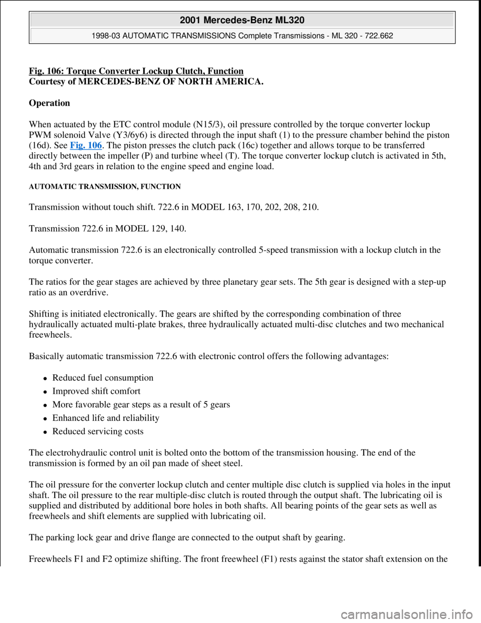
Fig. 106: Torque Converter Lockup Clutch, Function
Courtesy of MERCEDES-BENZ OF NORTH AMERICA.
Operation
When actuated by the ETC control module (N15/3), oil pressure controlled by the torque converter lockup
PWM solenoid Valve (Y3/6y6) is directed through the input shaft (1) to the pressure chamber behind the piston
(16d). See Fig. 106
. The piston presses the clutch pack (16c) together and allows torque to be transferred
directly between the impeller (P) and turbine wheel (T). The torque converter lockup clutch is activated in 5th,
4th and 3rd gears in relation to the engine speed and engine load.
AUTOMATIC TRANSMISSION, FUNCTION
Transmission without touch shift. 722.6 in MODEL 163, 170, 202, 208, 210.
Transmission 722.6 in MODEL 129, 140.
Automatic transmission 722.6 is an electronically controlled 5-speed transmission with a lockup clutch in the
torque converter.
The ratios for the gear stages are achieved by three planetary gear sets. The 5th gear is designed with a step-up
ratio as an overdrive.
Shifting is initiated electronically. The gears are shifted by the corresponding combination of three
hydraulically actuated multi-plate brakes, three hydraulically actuated multi-disc clutches and two mechanical
freewheels.
Basically automatic transmission 722.6 with electronic control offers the following advantages:
Reduced fuel consumption
Improved shift comfort
More favorable gear steps as a result of 5 gears
Enhanced life and reliability
Reduced servicing costs
The electrohydraulic control unit is bolted onto the bottom of the transmission housing. The end of the
transmission is formed by an oil pan made of sheet steel.
The oil pressure for the converter lockup clutch and center multiple disc clutch is supplied via holes in the input
shaft. The oil pressure to the rear multiple-disc clutch is routed through the output shaft. The lubricating oil is
supplied and distributed by additional bore holes in both shafts. All bearing points of the gear sets as well as
freewheels and shift elements are supplied with lubricating oil.
The parking lock gear and drive flange are connected to the output shaft by gearing.
Freewheels F1 and F2 optimize shiftin
g. The front freewheel (F1) rests against the stator shaft extension on the
2001 Mercedes-Benz ML320
1998-03 AUTOMATIC TRANSMISSIONS Complete Transmissions - ML 320 - 722.662
me
Saturday, October 02, 2010 3:15:28 PMPage 183 © 2006 Mitchell Repair Information Company, LLC.
Page 1358 of 4133
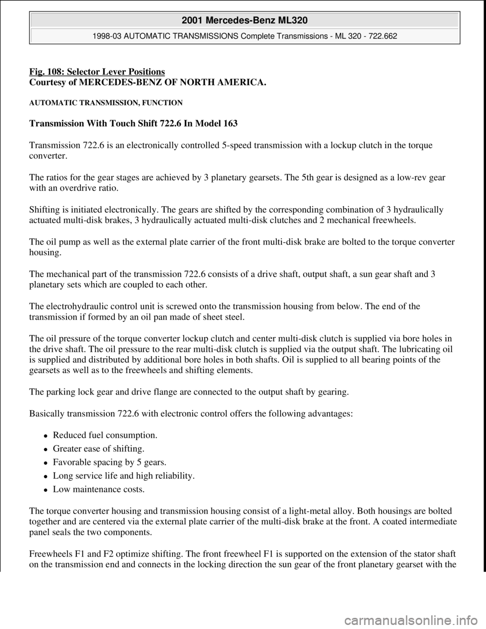
Fig. 108: Selector Lever Positions
Courtesy of MERCEDES-BENZ OF NORTH AMERICA.
AUTOMATIC TRANSMISSION, FUNCTION
Transmission With Touch Shift 722.6 In Model 163
Transmission 722.6 is an electronically controlled 5-speed transmission with a lockup clutch in the torque
converter.
The ratios for the gear stages are achieved by 3 planetary gearsets. The 5th gear is designed as a low-rev gear
with an overdrive ratio.
Shifting is initiated electronically. The gears are shifted by the corresponding combination of 3 hydraulically
actuated multi-disk brakes, 3 hydraulically actuated multi-disk clutches and 2 mechanical freewheels.
The oil pump as well as the external plate carrier of the front multi-disk brake are bolted to the torque converter
housing.
The mechanical part of the transmission 722.6 consists of a drive shaft, output shaft, a sun gear shaft and 3
planetary sets which are coupled to each other.
The electrohydraulic control unit is screwed onto the transmission housing from below. The end of the
transmission if formed by an oil pan made of sheet steel.
The oil pressure of the torque converter lockup clutch and center multi-disk clutch is supplied via bore holes in
the drive shaft. The oil pressure to the rear multi-disk clutch is supplied via the output shaft. The lubricating oil
is supplied and distributed by additional bore holes in both shafts. Oil is supplied to all bearing points of the
gearsets as well as to the freewheels and shifting elements.
The parking lock gear and drive flange are connected to the output shaft by gearing.
Basically transmission 722.6 with electronic control offers the following advantages:
Reduced fuel consumption.
Greater ease of shifting.
Favorable spacing by 5 gears.
Long service life and high reliability.
Low maintenance costs.
The torque converter housing and transmission housing consist of a light-metal alloy. Both housings are bolted
together and are centered via the external plate carrier of the multi-disk brake at the front. A coated intermediate
panel seals the two components.
Freewheels F1 and F2 optimize shifting. The front freewheel F1 is supported on the extension of the stator shaft
on the transmission end and connects in the lockin
g direction the sun gear of the front planetary gearset with the
2001 Mercedes-Benz ML320
1998-03 AUTOMATIC TRANSMISSIONS Complete Transmissions - ML 320 - 722.662
me
Saturday, October 02, 2010 3:15:28 PMPage 189 © 2006 Mitchell Repair Information Company, LLC.
Page 1446 of 4133
Task
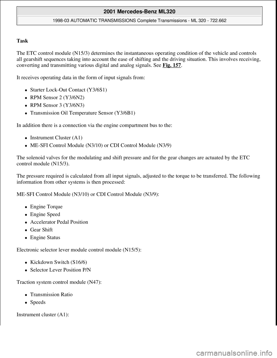
The ETC control module (N15/3) determines the instantaneous operating condition of the vehicle and controls
all gearshift sequences taking into account the ease of shifting and the driving situation. This involves receiving,
converting and transmitting various digital and analog signals. See Fig. 157
.
It receives operating data in the form of input signals from:
Starter Lock-Out Contact (Y3/6S1)
RPM Sensor 2 (Y3/6N2)
RPM Sensor 3 (Y3/6N3)
Transmission Oil Temperature Sensor (Y3/6B1)
In addition there is a connection via the engine compartment bus to the:
Instrument Cluster (A1)
ME-SFI Control Module (N3/10) or CDI Control Module (N3/9)
The solenoid valves for the modulating and shift pressure and for the gear changes are actuated by the ETC
control module (N15/3).
The pressure required is calculated from all input signals, adjusted to the torque to be transferred. The following
information from other systems is then processed:
ME-SFI Control Module (N3/10) or CDI Control Module (N3/9):
Engine Torque
Engine Speed
Accelerator Pedal Position
Gear Shift
Engine Status
Electronic selector lever module control module (N15/5):
Kickdown Switch (S16/6)
Selector Lever Position P/N
Traction system control module (N47):
Transmission Ratio
Speeds
Instrument cluster (A1):
2001 Mercedes-Benz ML320
1998-03 AUTOMATIC TRANSMISSIONS Complete Transmissions - ML 320 - 722.662
me
Saturday, October 02, 2010 3:15:29 PMPage 277 © 2006 Mitchell Repair Information Company, LLC.
Page 1449 of 4133
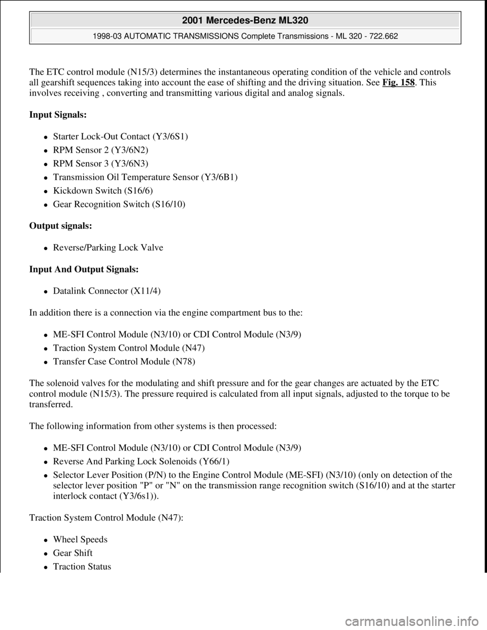
The ETC control module (N15/3) determines the instantaneous operating condition of the vehicle and controls
all gearshift sequences taking into account the ease of shifting and the driving situation. See Fig. 158
. This
involves receiving , converting and transmitting various digital and analog signals.
Input Signals:
Starter Lock-Out Contact (Y3/6S1)
RPM Sensor 2 (Y3/6N2)
RPM Sensor 3 (Y3/6N3)
Transmission Oil Temperature Sensor (Y3/6B1)
Kickdown Switch (S16/6)
Gear Recognition Switch (S16/10)
Output signals:
Reverse/Parking Lock Valve
Input And Output Signals:
Datalink Connector (X11/4)
In addition there is a connection via the engine compartment bus to the:
ME-SFI Control Module (N3/10) or CDI Control Module (N3/9)
Traction System Control Module (N47)
Transfer Case Control Module (N78)
The solenoid valves for the modulating and shift pressure and for the gear changes are actuated by the ETC
control module (N15/3). The pressure required is calculated from all input signals, adjusted to the torque to be
transferred.
The following information from other systems is then processed:
ME-SFI Control Module (N3/10) or CDI Control Module (N3/9)
Reverse And Parking Lock Solenoids (Y66/1)
Selector Lever Position (P/N) to the Engine Control Module (ME-SFI) (N3/10) (only on detection of the
selector lever position "P" or "N" on the transmission range recognition switch (S16/10) and at the starter
interlock contact (Y3/6s1)).
Traction System Control Module (N47):
Wheel Speeds
Gear Shift
Traction Status
2001 Mercedes-Benz ML320
1998-03 AUTOMATIC TRANSMISSIONS Complete Transmissions - ML 320 - 722.662
me
Saturday, October 02, 2010 3:15:29 PMPage 280 © 2006 Mitchell Repair Information Company, LLC.
Page 1450 of 4133
Transfer Case Control Module (N78):
Position of Transfer Case (off-road or on-road ratio)
Engine Torque
Engine Speed
Accelerator Pedal Position
Gear Soft
Engine Status
The following information is output to other systems:
ME-SFI Control Module (N3/10) or CDI Control Module (N3/9):
Kickdown Switch (S16/6)
Engage Drive Mode
Traction System Control Module (N47):
Transmission Ratio
Speeds
Oil Level Control, Function
Operation - The oil level control system seals the opening between the oil gallery and gearset chamber so that
the rotating gearsets do not splash about in oil as the oil level rises. The oil level control reduces power loss and
prevents oil from being thrown out of the transmission housing at high oil temperatures.
Float, Location/Function
See SHIFT PRESSURE REGULATING VALVE, LOCATION/TASK/FUNCTION
.
Transmission Housing Breathing, Location/Task
See TRANSMISSION HOUSING BREATHING, LOCATION/TASK
.
Function Of Torque Converter Lockup Clutch Control
Operation
2001 Mercedes-Benz ML320
1998-03 AUTOMATIC TRANSMISSIONS Complete Transmissions - ML 320 - 722.662
me
Saturday, October 02, 2010 3:15:29 PMPage 281 © 2006 Mitchell Repair Information Company, LLC.
Page 1454 of 4133
Courtesy of MERCEDES-BENZ OF NORTH AMERICA.
Operation
The driver's wish for maximum acceleration of the vehicle is met with the kick-down function. See Fig. 160.
When the kick-down switch (S16/6) is operated a CAN Signal is passed on from the electronic selector lever
module control module (N15/5) to the ETC control module (N15/3) via the electronic accelerator.
Based on this information the ETC control module (N15/3) actuates the solenoid valves so that the upshifts and
downshifts take place at higher engine speeds in order to achieve maximum performance.
Kick-Down Switch, Location/Task/Design
See KICK
-DOWN SWITCH, LOCATION/TASK/DESIGN.
Hydropneumatic Transmission Control, Function (Without Touch Shift)
Operation
The hydropneumatic transmission control is divided into electronic and hydraulic transmission control.
While the electronic transmission control is responsible for gear selection and for matching the pressures to the
torque to be transmitted, the transmission's power supply control occurs via hydraulic elements in the
electrohydraulic control module. The oil supply to the hydraulic elements, such as the hydrodynamic torque
converter, the shift elements and the hydraulic transmission control, is provided by way of an oil pump
connected with the torque converter.
The electronic transmission control (ETC) allows for the precise adaptation of pressures to the corresponding
operating conditions and to the engine output during the gearshift phase, resulting in a noticeable improvement
in shift quality.
It is possible to reach the engine RPM limit in the individual gears using full throttle and kick-down. The shift
range can be changed in the forward gears while driving, but the electronic transmission control (ETC) employs
a downshift safeguard to prevent over-revving the engine.
The system offers the additional advantage of flexible adaptation to different vehicle and engine variants.
ETC Control Module, Location/Task
See ETC CONTROL UNIT, LOCATION/TASK
.
Electric Control Module, Location/Task/Design/Function
See ELECTRONIC CONTROL MODULE, LOCATION/TASK/DESIGN/FUNCTION
.
Kickdown Switch, Location/Task/Design/Function Model 163 Without Touch Shift
2001 Mercedes-Benz ML320
1998-03 AUTOMATIC TRANSMISSIONS Complete Transmissions - ML 320 - 722.662
me
Saturday, October 02, 2010 3:15:29 PMPage 285 © 2006 Mitchell Repair Information Company, LLC.
Page 1471 of 4133
Basically automatic transmission 722.6 with electronic control offers the following advantages:
Reduced Fuel Consumption
Improved Shift Comfort
More Favorable Gear Steps As A Result Of 5 Gears
Enhanced Life And Reliability
Reduced Servicing Costs
The electrohydraulic control unit is bolted onto the bottom of the transmission housing. The end of the
transmission is formed by an oil pan made of sheet steel.
The oil pressure for the converter lockup clutch and center multiple-disc clutch is supplied via holes in the input
shaft. The oil pressure to the rear multiple-disc clutch is routed through the output shaft. The lubricating oil is
supplied and distributed by additional bore holes in both shafts. All bearing points of the gear sets as well as
freewheels and shift elements are supplied with lubricating oil.
The parking lock gear and drive flange are connected to the output shaft by gearing.
Freewheels F1 and F2 optimize shifting. The front freewheel (F1) rests against the stator shaft extension on the
transmission side and connects the sun gear of the front planetary gear set to the transmission housing in the
locking direction.
The torque converter housing and transmission housing are made of a metal alloy. They are bolted together and
centered via the outer multiple-disc carrier of the multiple-disc brake B1. A coated intermediate panel seals the
two components.
The oil pump and outer multiple-disc carrier of the front multiple-disc brake are bolted to the converter housing.
The mechanical part consists of the propeller shaft, output shaft, a sun gear shaft and three planetary gearsets
which are coupled together.
In transmissions for powerful engines, the planetary gearsets have 4 planetary gears, while for less powerful
engines the front and rear planetary gear system has three planetary gear wheels. The stator shaft is pressed into
this and is secured against turning by a spline.
The rear freewheel F2 connects the sun gear of the center planetary gear set to the sun gear of the rear planetary
gearset in the locking direction.
The electrohydraulic control unit consists of the shift plate made of light alloy for hydraulic control and an
electronic control unit.
The electrical control unit consists of a supporting body made of plastic in which the electrical components are
combined. The shell is screwed to the shift plate. Conductor tracks which are integrated into the shell, connect
the electric components to a plug connector. This 13-pin plug connector forms the connection with the vehicle-
side wiring harness and with the ETC 5 (electronic transmission control) control module (N15/5) via a bayonet
lock.
2001 Mercedes-Benz ML320
1998-03 AUTOMATIC TRANSMISSIONS Complete Transmissions - ML 320 - 722.662
me
Saturday, October 02, 2010 3:15:30 PMPage 302 © 2006 Mitchell Repair Information Company, LLC.
Page 2068 of 4133
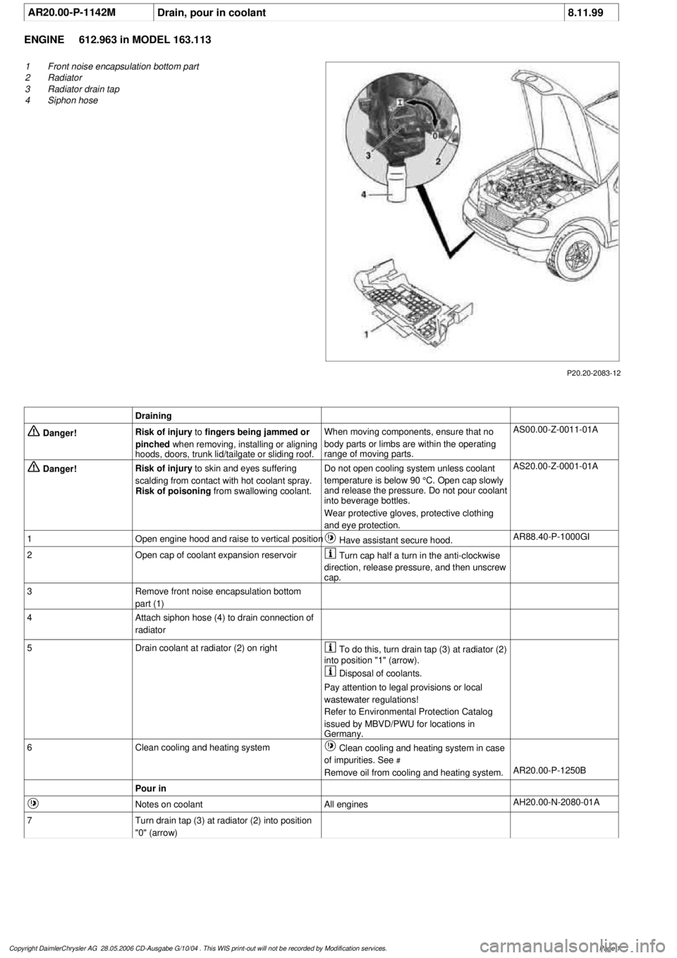
AR20.00-P-1142M
Drain, pour in coolant
8.11.99
ENGINE
612.963 in MODEL 163.113
P20.20-2083-12
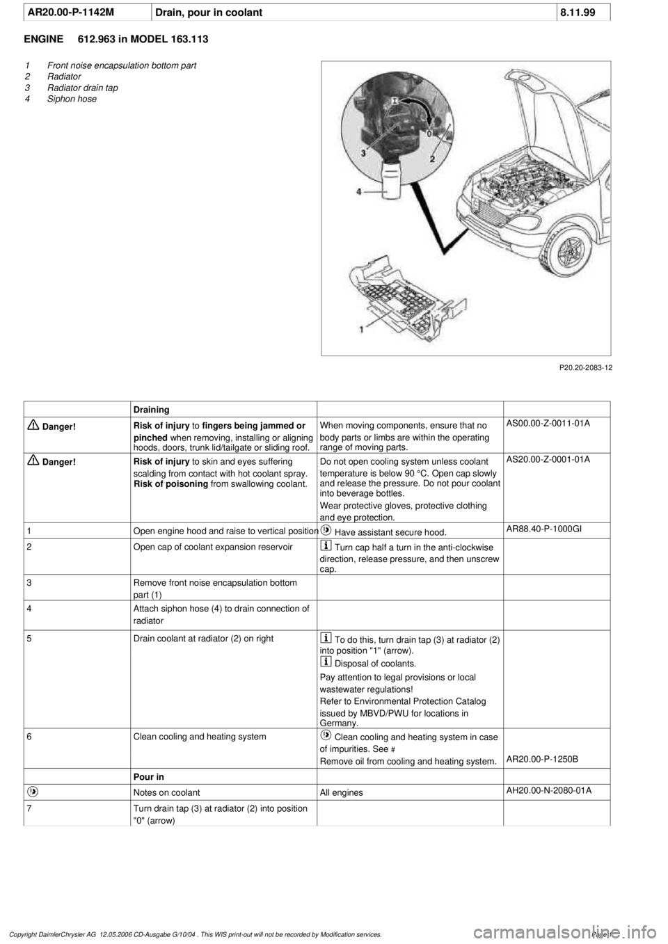
1
Front noise encapsulation bottom part
2
Radiator
3
Radiator drain tap
4
Siphon hose
Draining
Danger!
Risk of injury
to
fingers being jammed or
pinched
when removing, installing or aligning
hoods, doors, trunk lid/tailgate or sliding roof.
When moving components, ensure that no
body parts or limbs are within the operating
range of moving parts.
AS00.00-Z-0011-01A
Danger!
Risk of injury
to skin and eyes suffering
scalding from contact with hot coolant spray.
Risk of poisoning
from swallowing coolant.
Do not open cooling system unless coolant
temperature is below 90 °C. Open cap slowly
and release the pressure. Do not pour coolant
into beverage bottles.
Wear protective gloves, protective clothing
and eye protection.
AS20.00-Z-0001-01A
1
Open engine hood and raise to vertical position
Have assistant secure hood.
AR88.40-P-1000GI
2
Open cap of coolant expansion reservoir
Turn cap half a turn in the anti-clockwise
direction, release pressure, and then unscrew
cap.
3
Remove front noise encapsulation bottom
part (1)
4
Attach siphon hose (4) to drain connection of
radiator
5
Drain coolant at radiator (2) on right
To do this, turn drain tap (3) at radiator (2)
into position "1" (arrow).
Disposal of coolants.
Pay attention to legal provisions or local
wastewater regulations!
Refer to Environmental Protection Catalog
issued by MBVD/PWU for locations in
Germany.
6
Clean cooling and heating system
Clean cooling and heating system in case
of impurities. See
#
Remove oil from cooling and heating system.
AR20.00-P-1250B
Pour in
Notes on coolant
All engines
AH20.00-N-2080-01A
7
Turn drain tap (3) at radiator (2) into position
"0" (arrow)
Copyright DaimlerChrysler AG 12.05.2006 CD-Ausgabe G/10/04 . This WIS print-out will not be recorde
d by Modification services.
Page 1
Page 2075 of 4133
AR20.00-P-1142M
Drain, pour in coolant
8.11.99
ENGINE
612.963 in MODEL 163.113
P20.20-2083-12
1
Front noise encapsulation bottom part
2
Radiator
3
Radiator drain tap
4
Siphon hose
Draining
Danger!
Risk of injury
to
fingers being jammed or
pinched
when removing, installing or aligning
hoods, doors, trunk lid/tailgate or sliding roof.
When moving components, ensure that no
body parts or limbs are within the operating
range of moving parts.
AS00.00-Z-0011-01A
Danger!
Risk of injury
to skin and eyes suffering
scalding from contact with hot coolant spray.
Risk of poisoning
from swallowing coolant.
Do not open cooling system unless coolant
temperature is below 90 °C. Open cap slowly
and release the pressure. Do not pour coolant
into beverage bottles.
Wear protective gloves, protective clothing
and eye protection.
AS20.00-Z-0001-01A
1
Open engine hood and raise to vertical position
Have assistant secure hood.
AR88.40-P-1000GI
2
Open cap of coolant expansion reservoir
Turn cap half a turn in the anti-clockwise
direction, release pressure, and then unscrew
cap.
3
Remove front noise encapsulation bottom
part (1)
4
Attach siphon hose (4) to drain connection of
radiator
5
Drain coolant at radiator (2) on right
To do this, turn drain tap (3) at radiator (2)
into position "1" (arrow).
Disposal of coolants.
Pay attention to legal provisions or local
wastewater regulations!
Refer to Environmental Protection Catalog
issued by MBVD/PWU for locations in
Germany.
6
Clean cooling and heating system
Clean cooling and heating system in case
of impurities. See
#
Remove oil from cooling and heating system.
AR20.00-P-1250B
Pour in
Notes on coolant
All engines
AH20.00-N-2080-01A
7
Turn drain tap (3) at radiator (2) into position
"0" (arrow)
Copyright DaimlerChrysler AG 28.05.2006 CD-Ausgabe G/10/04 . This WIS print-out will not be recorde
d by Modification services.
Page 1
Page 2087 of 4133

8
Attach guard plate for radiator/condenser
y
Guard plate for radiator/condenser
Engine 606 in model 124,
Engine 606.961 in model 140,
Engine 112, 113, 604, 605, 611.960 in model
202,
Engine 602.983, 612.966 in model 461,
Engine 628.962, 612.965, 606.964, 112.945,
113.962/ 982 in model 463,
Engine 111, 112, 611.962, 612.962 in model
203,
Engine 112, 113, 611.961, 612.961, 613.961
in model 210,
Engine 112 in model 170,
Engine 112 in model 220,
Engine 113 in model 211, 215, 220,
Engine 112 in model 208,
Engine 112, 113, 612.963, 628.963 in model
163,
Engine 112.923 /943, 113.961 in model 129,
Engine 137, 275 in model 215, 220,
Engine 613.960, 628.960 in model 220,
Engine 113.992 in model 230.474,
Engine 271 in model 209, 203,
Engine 285.950 in model 240.078 /178,
Engine 612.967 in model 209.316,
Engine 648 in model 220
Engine 112.951 in model 639.601/603/ 605/
701 /703 /705 /801 /803 /805
Engine 646.983 /984 in model 639.601/
603 /605 /701 /703 /705 /801 /803 /805
Engine 646.982 in model 639.601/ 603/ 605/
701 /703 /705
WF58.50-P-0110-01A
9
Remove air cleaner housing (5)
10
Remove air intake pipe (6) with resonance
tube (7)
Separate connector of hot film mass air
flow sensor (HFM) for this step and unbolt air
intake pipe at cylinder head cover
The air intake pipe is attached at the rear
at the intake manifold with a plastic plate.
Do not damage the plastic strap.
Engine 112.942/ 970
AR07.07-P-1454A
Engine 113.942/ 965/ 981
AR07.07-P-1454MV
Danger!
Risk of explosion
caused by fuel igniting,
risk of poisoning
caused by inhaling and
swallowing fuel as well as
risk of injury
to
eyes and skin caused by contact with fuel.
No fire, sparks, open flames or smoking.
Pour fuels only into suitable and appropriately
marked containers.
Wear protective clothing when handling fuel.
AS47.00-Z-0001-01A
11
Disconnect fuel line at fuel rail
Release fuel pressure at service valve!
Collect fuel!
Engine 112:
#
*BA07.52-P-1001-01A
Engine 113:
#
*BA07.52-P-1001-01A
Pressure hose
*119589046300
12
Remove right and left ignition coils (12)
AR15.12-P-2003A
13
Remove right and left cylinder head covers (13)
AR01.20-P-5014B
14
Remove the intake manifold (14)
Installation:
On vehicles with engine
damage, the intake manifold must be
examined for swarfs before assembling and
any swarfs present must be removed, in order
to avoid consequential damage.
AR09.20-P-1310A
The intake manifold system must not be
disassembled.
Remove intake manifold with fuel distributor
15.1
Remove camshaft position sensor (15)
Only necessary if the right cylinder head is
removed.
AR15.10-P-2000A
Copyright DaimlerChrysler AG 20.05.2006 CD-Ausgabe G/10/04 . This WIS print-out will not be recorde
d by Modification services.
Page 3