low oil pressure MERCEDES-BENZ ML350 1997 Complete Owner's Guide
[x] Cancel search | Manufacturer: MERCEDES-BENZ, Model Year: 1997, Model line: ML350, Model: MERCEDES-BENZ ML350 1997Pages: 4133, PDF Size: 88.89 MB
Page 2095 of 4133

8
Attach guard plate for radiator/condenser
y
Guard plate for radiator/condenser
Engine 606 in model 124,
Engine 606.961 in model 140,
Engine 112, 113, 604, 605, 611.960 in model
202,
Engine 602.983, 612.966 in model 461,
Engine 628.962, 612.965, 606.964, 112.945,
113.962/ 982 in model 463,
Engine 111, 112, 611.962, 612.962 in model
203,
Engine 112, 113, 611.961, 612.961, 613.961
in model 210,
Engine 112 in model 170,
Engine 112 in model 220,
Engine 113 in model 211, 215, 220,
Engine 112 in model 208,
Engine 112, 113, 612.963, 628.963 in model
163,
Engine 112.923 /943, 113.961 in model 129,
Engine 137, 275 in model 215, 220,
Engine 613.960, 628.960 in model 220,
Engine 113.992 in model 230.474,
Engine 271 in model 209, 203,
Engine 285.950 in model 240.078 /178,
Engine 612.967 in model 209.316,
Engine 648 in model 220
Engine 112.951 in model 639.601/603/ 605/
701 /703 /705 /801 /803 /805
Engine 646.983 /984 in model 639.601/
603 /605 /701 /703 /705 /801 /803 /805
Engine 646.982 in model 639.601/ 603/ 605/
701 /703 /705
WF58.50-P-0110-01A
9
Remove air cleaner housing (5)
10
Remove air intake pipe (6) with resonance
tube (7)
Separate connector of hot film mass air
flow sensor (HFM) for this step and unbolt air
intake pipe at cylinder head cover
The air intake pipe is attached at the rear
at the intake manifold with a plastic plate.
Do not damage the plastic strap.
Engine 112.942/ 970
AR07.07-P-1454A
Engine 113.942/ 965/ 981
AR07.07-P-1454MV
Danger!
Risk of explosion
caused by fuel igniting,
risk of poisoning
caused by inhaling and
swallowing fuel as well as
risk of injury
to
eyes and skin caused by contact with fuel.
No fire, sparks, open flames or smoking.
Pour fuels only into suitable and appropriately
marked containers.
Wear protective clothing when handling fuel.
AS47.00-Z-0001-01A
11
Disconnect fuel line at fuel rail
Release fuel pressure at service valve!
Collect fuel!
Engine 112:
#
*BA07.52-P-1001-01A
Engine 113:
#
*BA07.52-P-1001-01A
Pressure hose
*119589046300
12
Remove right and left ignition coils (12)
AR15.12-P-2003A
13
Remove right and left cylinder head covers (13)
AR01.20-P-5014B
14
Remove the intake manifold (14)
Installation:
On vehicles with engine
damage, the intake manifold must be
examined for swarfs before assembling and
any swarfs present must be removed, in order
to avoid consequential damage.
AR09.20-P-1310A
The intake manifold system must not be
disassembled.
Remove intake manifold with fuel distributor
15.1
Remove camshaft position sensor (15)
Only necessary if the right cylinder head is
removed.
AR15.10-P-2000A
Copyright DaimlerChrysler AG 20.05.2006 CD-Ausgabe G/10/04 . This WIS print-out will not be recorde
d by Modification services.
Page 3
Page 2105 of 4133

GF54.30-P-2002A
Display instruments, location / task / function
24.10.96
MODEL
129, 140 as of 1.6.96,
163, 168, 170,
202 as of 1.8.96,
208 up to 31.7.99,
210 as of 1.6.96 up to 30.6.99
Display
Type of data transmission
D
Outside temperature indicator (A1p4)
D
Fuel level gauge (A1p2)
D
Engine oil pressure gauge (A1p3), only
model 129 and model 140
D
Low windshield washer fluid level
indicator lamp (A1e13), model 163 as of
01.09.01
Direct lines
GF54.30-P-3004A
D
Total mileage odometer (A1h4)
D
Electronic speedometer (A1p8)
D
Tachometer (A1p5)
D
Coolant temperature gauge (A1p1)
D
Active service system (ASSYST)
D
Gear indicator (A1p12), only model 168
CAN data lines
GF54.30-P-3005A
D
Electronic clock
Internal
GF54.30-P-3011A
Copyright DaimlerChrysler AG 04.06.2006 CD-Ausgabe G/10/04 . This WIS print-out will not be recorde
d by Modification services.
Page 1
Page 2144 of 4133
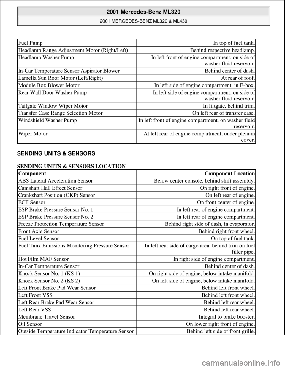
SENDING UNITS & SENSORS
SENDING UNITS & SENSORS LOCATION
Fuel PumpIn top of fuel tank.
Headlamp Range Adjustment Motor (Right/Left)Behind respective headlamp.
Headlamp Washer PumpIn left front of engine compartment, on side of
washer fluid reservoir.
In-Car Temperature Sensor Aspirator BlowerBehind center of dash.
Lamella Sun Roof Motor (Left/Right)At rear of roof.
Module Box Blower MotorIn left side of engine compartment, in E-box.
Rear Wall Door Washer PumpIn left side of engine compartment, on side of
washer fluid reservoir.
Tailgate Window Wiper MotorIn liftgate, behind trim.
Transfer Case Range Selection MotorOn left rear of transfer case.
Windshield Washer PumpIn left front of engine compartment, on washer fluid
reservoir.
Wiper MotorAt left rear of engine compartment, under plenum
cover.
ComponentComponent Location
ABS Lateral Acceleration SensorBelow center console, behind shift assembly.
Camshaft Hall Effect SensorOn right front of engine.
Crankshaft Position (CKP) SensorOn left rear of engine.
ECT SensorOn front center of engine.
ESP Brake Pressure Sensor No. 1In left rear of engine compartment.
ESP Brake Pressure Sensor No. 2In left rear of engine compartment.
Freeze Protection Temperature SensorBehind right side of dash, in evaporator.
Front Axle SensorBehind right front wheel.
Fuel Level SensorOn top of fuel tank.
Fuel Tank Emissions Monitoring Pressure SensorIn left rear side of cargo area, behind trim on fuel
filler pipe.
Hot Film MAF SensorIn right side of engine compartment.
In-Car Temperature SensorBehind center of dash.
Knock Sensor No. 1 (KS 1)On right side of engine, below intake manifold.
Knock Sensor No. 2 (KS 2)On left side of engine, below intake manifold.
Left Front Brake Pad Wear SensorBehind left front wheel.
Left Front VSSBehind left front wheel.
Left Rear Brake Pad Wear SensorBehind left rear wheel.
Left Rear VSSBehind left rear wheel.
Membrane Travel SensorIntegral to brake booster.
Oil SensorOn lower right front of engine.
Outside Temperature Indicator Temperature SensorBehind left side of front grille.
2001 Mercedes-Benz ML320
2001 MERCEDES-BENZ ML320 & ML430
me
Saturday, October 02, 2010 3:21:17 PMPage 4 © 2006 Mitchell Repair Information Company, LLC.
Page 2156 of 4133
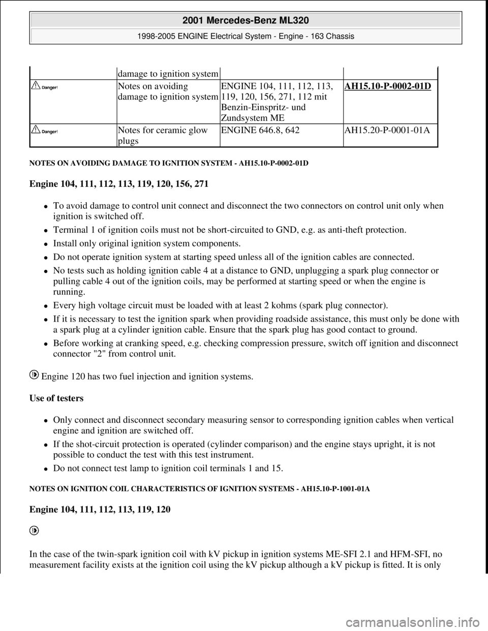
NOTES ON AVOIDING DAMAGE TO IGNITION SYSTEM - AH15.10-P-0002-01D
Engine 104, 111, 112, 113, 119, 120, 156, 271
To avoid damage to control unit connect and disconnect the two connectors on control unit only when
ignition is switched off.
Terminal 1 of ignition coils must not be short-circuited to GND, e.g. as anti-theft protection.
Install only original ignition system components.
Do not operate ignition system at starting speed unless all of the ignition cables are connected.
No tests such as holding ignition cable 4 at a distance to GND, unplugging a spark plug connector or
pulling cable 4 out of the ignition coils, may be performed at starting speed or when the engine is
running.
Every high voltage circuit must be loaded with at least 2 kohms (spark plug connector).
If it is necessary to test the ignition spark when providing roadside assistance, this must only be done with
a spark plug at a cylinder ignition cable. Ensure that the spark plug has good contact to ground.
Before working at cranking speed, e.g. checking compression pressure, switch off ignition and disconnect
connector "2" from control unit.
Engine 120 has two fuel injection and ignition systems.
Use of testers
Only connect and disconnect secondary measuring sensor to corresponding ignition cables when vertical
engine and ignition are switched off.
If the shot-circuit protection is operated (cylinder comparison) and the engine stays upright, it is not
possible to conduct the test with this test instrument.
Do not connect test lamp to ignition coil terminals 1 and 15.
NOTES ON IGNITION COIL CHARACTERISTICS OF IGNITION SYSTEMS - AH15.10-P-1001-01A
Engine 104, 111, 112, 113, 119, 120
In the case of the twin-spark ignition coil with kV pickup in ignition systems ME-SFI 2.1 and HFM-SFI, no
measurement facilit
y exists at the ignition coil using the kV pickup although a kV pickup is fitted. It is only
damage to ignition system
Notes on avoiding
damage to ignition systemENGINE 104, 111, 112, 113,
119, 120, 156, 271, 112 mit
Benzin-Einspritz- und
Zundsystem MEAH15.10-P-0002-01D
Notes for ceramic glow
plugsENGINE 646.8, 642AH15.20-P-0001-01A
2001 Mercedes-Benz ML320
1998-2005 ENGINE Electrical System - Engine - 163 Chassis
me
Saturday, October 02, 2010 3:18:54 PMPage 2 © 2006 Mitchell Repair Information Company, LLC.
Page 2239 of 4133

AF07.00-P-9000B
Engine runs rough, surges or does not turn over
29.4.02
ENGINE
611 in MODEL 203, 202, 210
ENGINE
612 in MODEL 163, 203, 210, 209
ENGINE
613 in MODEL 210, 220
ENGINE
628 in MODEL 163, 220, 211
ENGINE
646 in MODEL 203, 211
ENGINE
647 in MODEL 211
ENGINE
648 in MODEL 220, 211
ENGINE
668 in MODEL 168
ENGINE
612, 628 in MODEL 463
Modification notes
23.3.01
Supersedes STIP 07.16-014 dated 11.12.00
Damage code
Cause
Remedy
07 206 D5
High-pressure pump
To verify whether high pressure pump is
damaged.
#
High pressure pump of common rail
injection system is damaged mechanically.
1
Remove/install/replace high pressure
pump.
When the high pressure pump of the common
rail injection system is damaged metal chips
and/or damage to the pump drive (timing
drive) can occur due to contamination of the
injection system components.
2
Turn high pressure pump by hand with
driver.
If mechanical resistance can be felt,
perform the following tests. Clarify additional
work with ESKULAB by specifying repair work:
#
3
Check driver of high pressure pump or
mount in sprocket for damage (visual
check).
If high pressure pump is locked:
#
4
Check timing
5
Check timing drive for damage.
In each case:
#
6
Remove/install/replace timing chain.
If timing deviates by a crankshaft angle of
more than 20 degrees (corresponding to one
tooth skipped):
#
7
Check pressure loss.
8
Open low pressure connection on high
pressure pump return (plastic line in
area of pressure regulator valve) and
check connection point in rail for chips.
If chips are present when checking
injection system:
#
9
Thoroughly clean all fuel low pressure
lines as well as feed and return lines.
Flush and blow out with compressed air.
10
Remove fuel preheater and fuel filter
with filter housing, replace.
Fuel preheater is only installed in models
202, 203 and 163.
11
Remove/install/replace fuel cooler at
vehicle and engine end.
Not installed in model 210 up to 6/99 and
model 168.
12
Remove fuel tank, replace.
On engine 628:
#
13
Remove/install/replace electric supply
pump.
14
Remove/install/replace injectors, rail
(including pressure regulation valve and
rail pressure sensor), high pressure
lines and injector leak oil rail.*
Copyright DaimlerChrysler AG 28.05.2006 CD-Ausgabe G/10/04 . This WIS print-out will not be recorde
d by Modification services.
Page 1
Page 2374 of 4133
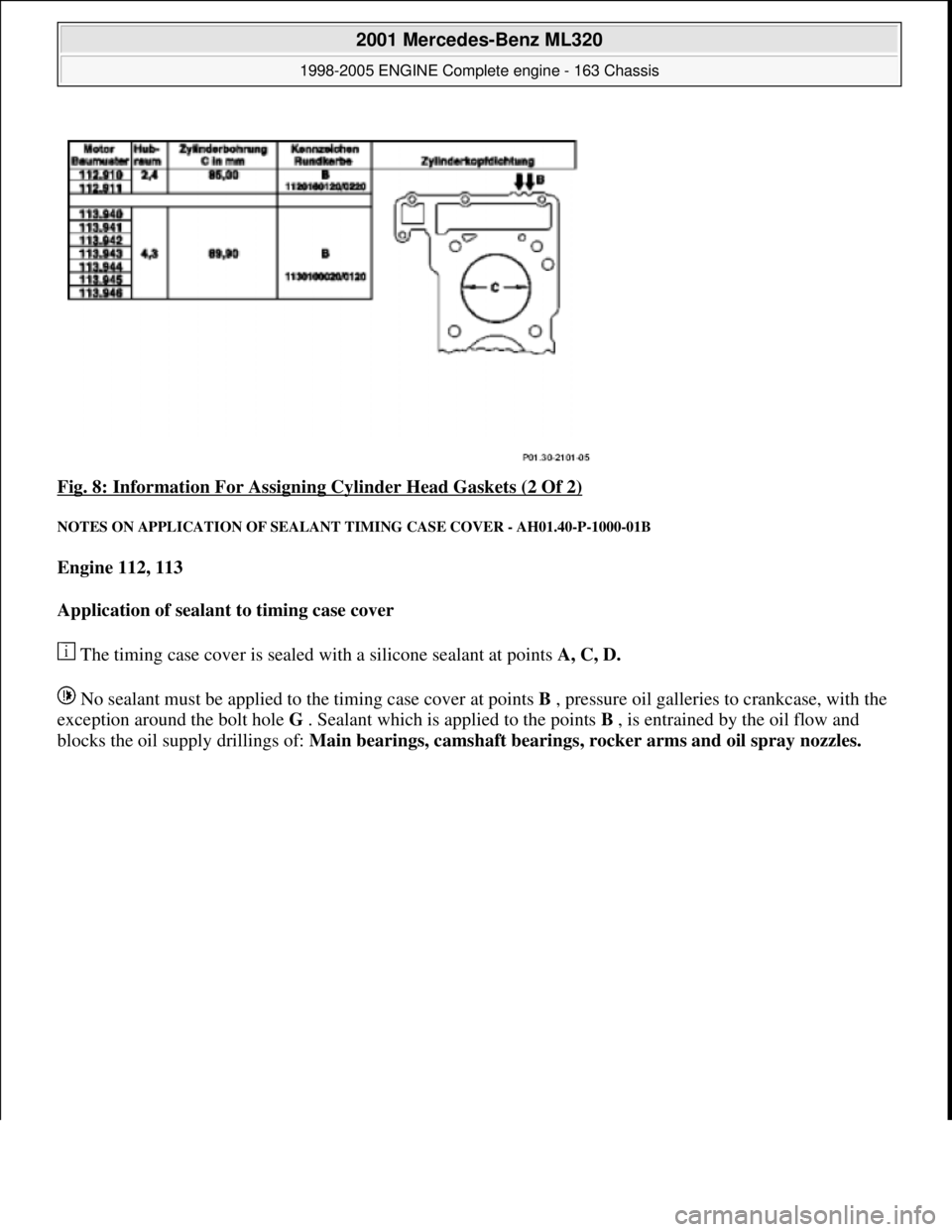
Fig. 8: Information For Assigning Cylinder Head Gaskets (2 Of 2)
NOTES ON APPLICATION OF SEALANT TIMING CASE COVER - AH01.40-P-1000-01B
Engine 112, 113
Application of sealant to timing case cover
The timing case cover is sealed with a silicone sealant at points A, C, D.
No sealant must be applied to the timing case cover at points B , pressure oil galleries to crankcase, with the
exception around the bolt hole G . Sealant which is applied to the points B , is entrained by the oil flow and
blocks the oil supply drillings of: Main bearings, camshaft bearings, rocker arms and oil spray nozzles.
2001 Mercedes-Benz ML320
1998-2005 ENGINE Complete engine - 163 Chassis
me
Saturday, October 02, 2010 3:17:56 PMPage 18 © 2006 Mitchell Repair Information Company, LLC.
Page 2409 of 4133
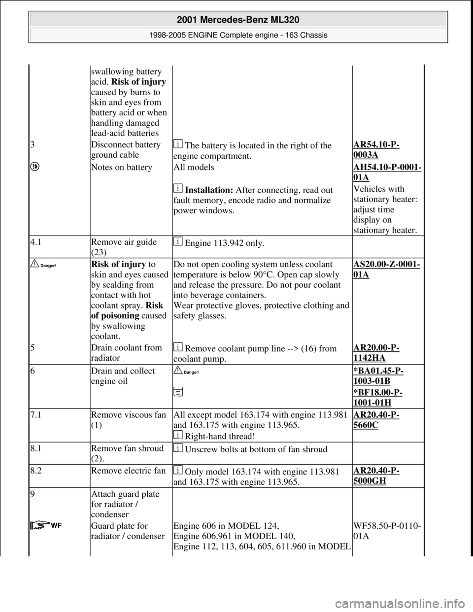
swallowing battery
acid. Risk of injury
caused by burns to
skin and eyes from
battery acid or when
handling damaged
lead-acid batteries
3Disconnect battery
ground cable The battery is located in the right of the
engine compartment.AR54.10-P-
0003A
Notes on batteryAll modelsAH54.10-P-0001-
01A
Installation: After connecting, read out
fault memory, encode radio and normalize
power windows.Vehicles with
stationary heater:
adjust time
display on
stationary heater.
4.1Remove air guide
(23) Engine 113.942 only.
Risk of injury to
skin and eyes caused
by scalding from
contact with hot
coolant spray. Risk
of poisoning caused
by swallowing
coolant.Do not open cooling system unless coolant
temperature is below 90° C. Open cap slowly
and release the pressure. Do not pour coolant
into beverage containers.
Wear protective gloves, pr otective clothing and
safety glasses.AS20.00-Z-0001-
01A
5Drain coolant from
radiator Remove coolant pump line --> (16) from
coolant pump.AR20.00-P-
1142HA
6Drain and collect
engine oil *BA01.45-P-
1003-01B
*BF18.00-P-
1001-01H
7.1Remove viscous fan
(1)All except model 163.174 with engine 113.981
and 163.175 with engine 113.965.
Right-hand thread!AR20.40-P-
5660C
8.1Remove fan shroud
(2). Unscrew bolts at bottom of fan shroud
8.2Remove electric fan Only model 163.174 with engine 113.981
and 163.175 with engine 113.965.AR20.40-P-
5000GH
9Attach guard plate
for radiator /
condenser
Guard plate for
radiator / condenserEngine 606 in MODEL 124,
Engine 606.961 in MODEL 140,
Engine 112, 113, 604, 605, 611.960 in MODEL WF58.50-P-0110-
01A
2001 Mercedes-Benz ML320
1998-2005 ENGINE Complete engine - 163 Chassis
me
Saturday, October 02, 2010 3:17:56 PMPage 53 © 2006 Mitchell Repair Information Company, LLC.
Page 2411 of 4133
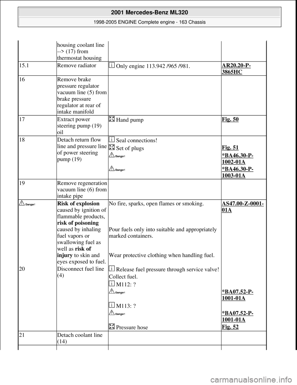
housing coolant line
--> (17) from
thermostat housing
15.1Remove radiator Only engine 113.942 /965 /981.AR20.20-P-
3865HC
16Remove brake
pressure regulator
vacuum line (5) from
brake pressure
regulator at rear of
intake manifold
17Extract power
steering pump (19)
oil Hand pumpFig. 50
18Detach return flow
line and pressure line
of power steering
pump (19) Seal connections!
Set of plugsFig. 51
*BA46.30-P-
1002-01A
*BA46.30-P-
1003-01A
19Remove regeneration
vacuum line (6) from
intake pipe
Risk of explosion
caused by ignition of
flammable products,
risk of poisoning
caused by inhaling
fuel vapors or
swallowing fuel as
well as risk of
injury to skin and
eyes exposed to fuel.No fire, sparks, ope n flames or smoking.AS47.00-Z-0001-
01A
Pour fuels only into suitable and appropriately
marked containers.
Wear protective clothing when handling fuel.
20Disconnect fuel line
(4) Release fuel pressure through service valve!
Collect fuel.
M112: ?
*BA07.52-P-
1001-01A
M113: ?
*BA07.52-P-
1001-01A
Pressure hoseFig. 52
21Detach coolant line
(14)
2001 Mercedes-Benz ML320
1998-2005 ENGINE Complete engine - 163 Chassis
me
Saturday, October 02, 2010 3:17:56 PMPage 55 © 2006 Mitchell Repair Information Company, LLC.
Page 2426 of 4133
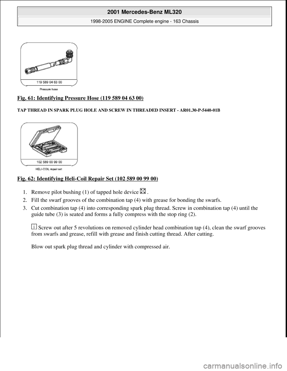
Fig. 61: Identifying Pressure Hose (119 589 04 63 00)
TAP THREAD IN SPARK PLUG HOLE AND SCRE W IN THREADED INSERT - AR01.30-P-5440-01B
Fig. 62: Identifying Heli-Coil Repair Set (102 589 00 99 00)
1. Remove pilot bushing (1) of tapped hole device .
2. Fill the swarf grooves of the combination tap (4) with grease for bonding the swarfs.
3. Cut combination tap (4) into corresponding spark pl ug thread. Screw in combination tap (4) until the
guide tube (3) is seated and forms a fully compress with the stop ring (2).
Screw out after 5 revolutions on removed cylinder head combination tap (4), clean the swarf grooves
from swarfs and grease, refi ll with grease and finish cutting thread. After cutting.
Blow out spark plu
g thread and cylinder with compressed air.
2001 Mercedes-Benz ML320
1998-2005 ENGINE Complete engine - 163 Chassis
me
Saturday, October 02, 2010 3:17:56 PMPage 70 © 2006 Mitchell Repair Information Company, LLC.
Page 2475 of 4133
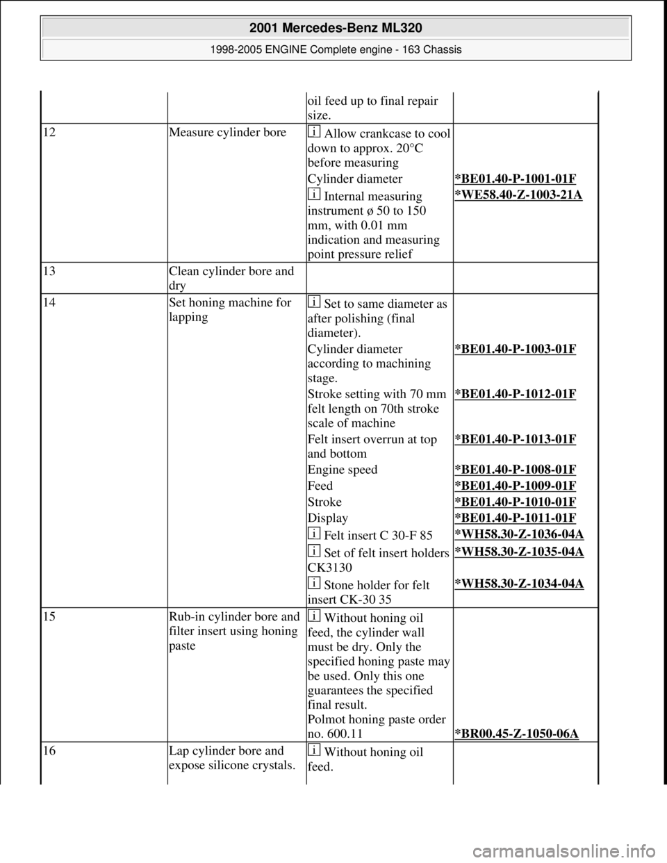
oil feed up to final repair
size.
12Measure cylinder boreAllow crankcase to cool
down to approx. 20°C
before measuring
Cylinder diameter*BE01.40-P-1001-01F
Internal measuring
instrument ø 50 to 150
mm, with 0.01 mm
indication and measuring
point pressure relief*WE58.40-Z-1003-21A
13Clean cylinder bore and
dry
14Set honing machine for
lapping Set to same diameter as
after polishing (final
diameter).
Cylinder diameter
according to machining
stage.*BE01.40-P-1003-01F
Stroke setting with 70 mm
felt length on 70th stroke
scale of machine*BE01.40-P-1012-01F
Felt insert overrun at top
and bottom*BE01.40-P-1013-01F
Engine speed*BE01.40-P-1008-01F
Feed*BE01.40-P-1009-01F
Stroke*BE01.40-P-1010-01F
Display*BE01.40-P-1011-01F
Felt insert C 30-F 85*WH58.30-Z-1036-04A
Set of felt insert holders
CK3130*WH58.30-Z-1035-04A
Stone holder for felt
insert CK-30 35*WH58.30-Z-1034-04A
15Rub-in cylinder bore and
filter insert using honing
paste Without honing oil
feed, the cylinder wall
must be dry. Only the
specified honing paste may
be used. Only this one
guarantees the specified
final result.
Polmot honing paste order
no. 600.11
*BR00.45-Z-1050-06A
16Lap cylinder bore and
expose silicone crystals. Without honing oil
feed.
2001 Mercedes-Benz ML320
1998-2005 ENGINE Complete engine - 163 Chassis
me
Saturday, October 02, 2010 3:17:57 PMPage 119 © 2006 Mitchell Repair Information Company, LLC.