suspension MERCEDES-BENZ ML350 1997 Complete Owner's Manual
[x] Cancel search | Manufacturer: MERCEDES-BENZ, Model Year: 1997, Model line: ML350, Model: MERCEDES-BENZ ML350 1997Pages: 4133, PDF Size: 88.89 MB
Page 3914 of 4133
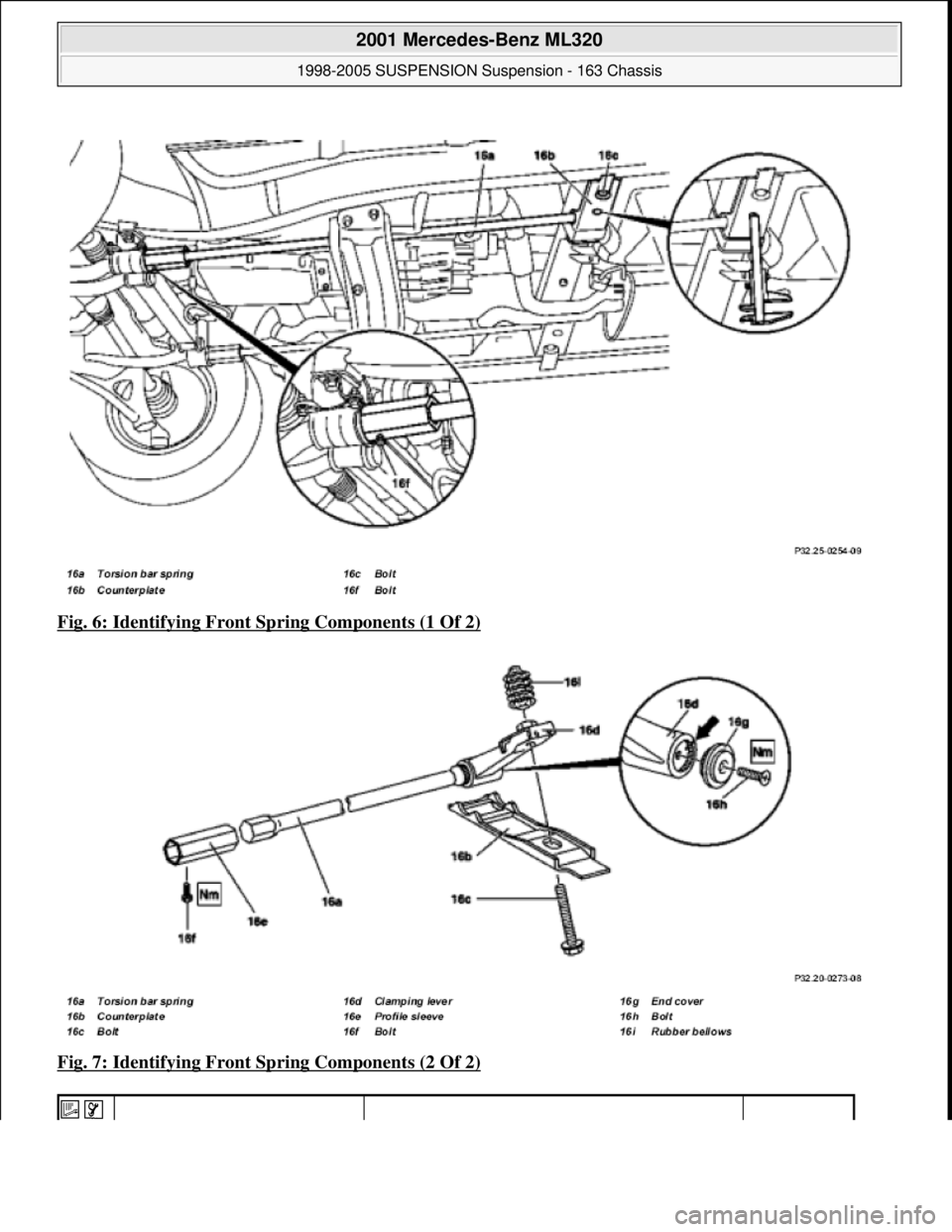
Fig. 6: Identifying Front Sp ring Components (1 Of 2)
Fig. 7: Identifying Front Sp ring Components (2 Of 2)
2001 Mercedes-Benz ML320
1998-2005 SUSPENSION Sus pension - 163 Chassis
me
Saturday, October 02, 2010 3:37:35 PMPage 6 © 2006 Mitchell Repair Information Company, LLC.
Page 3915 of 4133
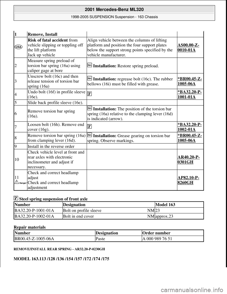
Steel spring suspension of front axle
Repair materials
REMOVE/INSTALL REAR SPRING - AR32.20-P-0230GH
MODEL 163.113 /128 /136 /154 /157 /172 /174 /175
1Remove, Install
Risk of fatal accident from
vehicle slipping or toppling off
the lift platform
Jack up vehicleAlign vehicle between the columns of lifting
platform and position the four support plates
below the support strong points specified by the
vehicle manufacturer.
AS00.00-Z-
0010-01A
2
Measure spring preload of
torsion bar spring (16a) using
caliper gage at bore
Installation: Restore spring preload.
3
Unscrew bolt (16c) and then
release tension of torsion bar
spring (16a) Installation: regrease bolt (16c). The rubber
bellows (16i) must be filled with grease.*BR00.45-Z-
1005-06A
4Undo bolt (16f) in profile sleeve
(16e). *BA32.20-P-
1001-01A
5Slide back profile sleeve (16e).
6Remove torsion bar spring
(16a). Installation: The position of the torsion bar
spring (16a) relative to the clamping lever (16d)
is indicated (arrow).
7Loosen bolt (16h). Remove end
cover (16g). *BA32.20-P-
1002-01A
8Remove torsion bar spring (16a)
from clamping lever (16d). Installation: Grease gearing on torsion bar
spring. Observe markings.*BR00.45-Z-
1005-06A
9Install in the reverse order
10
Check vehicle level at front and
rear axles with electronic
inclinometer and adjust if
necessary.
AR40.20-P-
0301GH
11
Check and correct headlamp
adjust
Check and correct headlamp
adjustment
AP82.10-P-
8260GH
Number Designation Model 163
BA32.20-P-1001-01ABolt on profile sleeveNM23
BA32.20-P-1002-01ABolt in end coverNMapprox.23
NumberDesignationOrder number
BR00.45-Z-1005-06APasteA 000 989 76 51
2001 Mercedes-Benz ML320
1998-2005 SUSPENSION Suspension - 163 Chassis
me
Saturday, October 02, 2010 3:37:35 PMPage 7 © 2006 Mitchell Repair Information Company, LLC.
Page 3916 of 4133
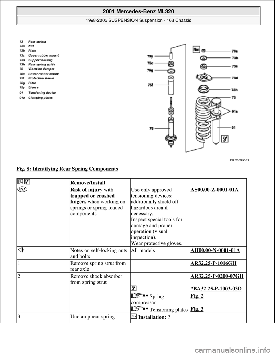
Fig. 8: Identifying Rear Spring Components
Remove/Install
Risk of injury with
trapped or crushed
fingers when working on
springs or spring-loaded
componentsUse only approved
tensioning devices;
additionally shield off
hazardous area if
necessary.
Inspect special tools for
damage and proper
operation (visual
inspection).
Wear protective gloves.AS00.00-Z-0001-01A
Notes on self-locking nuts
and boltsAll modelsAH00.00-N-0001-01A
1Remove spring strut from
rear axle AR32.25-P-1016GH
2Remove shock absorber
from spring strut AR32.25-P-0200-07GH
*BA32.25-P-1003-03D
Spring
compressorFig. 2
Tensioning platesFig. 3
3Unclamp rear spring Installation: ?
2001 Mercedes-Benz ML320
1998-2005 SUSPENSION Suspension - 163 Chassis
me
Saturday, October 02, 2010 3:37:35 PMPage 8 © 2006 Mitchell Repair Information Company, LLC.
Page 3917 of 4133
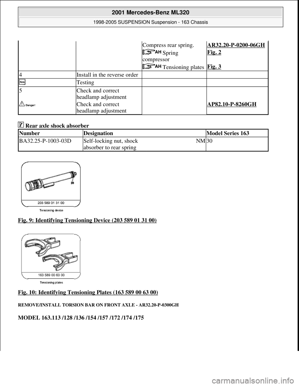
Rear axle shock absorber
Fig. 9: Identifying Tensioning Device (203 589 01 31 00)
Fig. 10: Identifying Tensioning Plates (163 589 00 63 00)
REMOVE/INSTALL TORSION BAR ON FRONT AXLE - AR32.20-P-0300GH
MODEL 163.113 /128 /136 /154 /157 /172 /174 /175
Compress rear spring.AR32.20-P-0200-06GH
Spring
compressorFig. 2
Tensioning platesFig. 3
4Install in the reverse order
Testing
5Check and correct
headlamp adjustment
Check and correct
headlamp adjustmentAP82.10-P-8260GH
NumberDesignationModel Series 163
BA32.25-P-1003-03DSelf-locking nut, shock
absorber to rear springNM30
2001 Mercedes-Benz ML320
1998-2005 SUSPENSION Sus pension - 163 Chassis
me
Saturday, October 02, 2010 3:37:35 PMPage 9 © 2006 Mitchell Repair Information Company, LLC.
Page 3918 of 4133
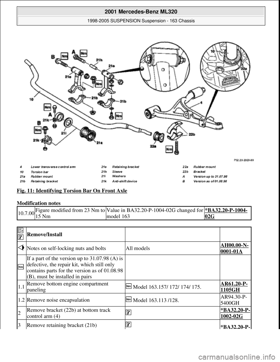
Fig. 11: Identifying Torsion Bar On Front Axle
Modification notes
10.7.00Figure modified from 23 Nm to
15 NmValue in BA32.20-P-1004-02G changed for
model 163*BA32.20-P-1004-
02G
Remove/Install
Notes on self-locking nuts and boltsAll modelsAH00.00-N-
0001-01A
If a part of the version up to 31.07.98 (A) is
defective, the repair kit, which still only
contains parts for the version as of 01.08.98
(B), must be installed in pairs
1.1Remove bottom engine compartment
paneling Model 163.157/ 172/ 174/ 175.AR61.20-P-
1105GH
1.2Remove noise encapsulation Model 163.113 /128.AR94.30-P-
5400GH
2Remove bracket (22b) at bottom track
control arm (4) *BA32.20-P-
1002-02G
3Remove retaining bracket (21b) *BA32.20-P-
2001 Mercedes-Benz ML320
1998-2005 SUSPENSION Suspension - 163 Chassis
me
Saturday, October 02, 2010 3:37:35 PMPage 10 © 2006 Mitchell Repair Information Company, LLC.
Page 3919 of 4133
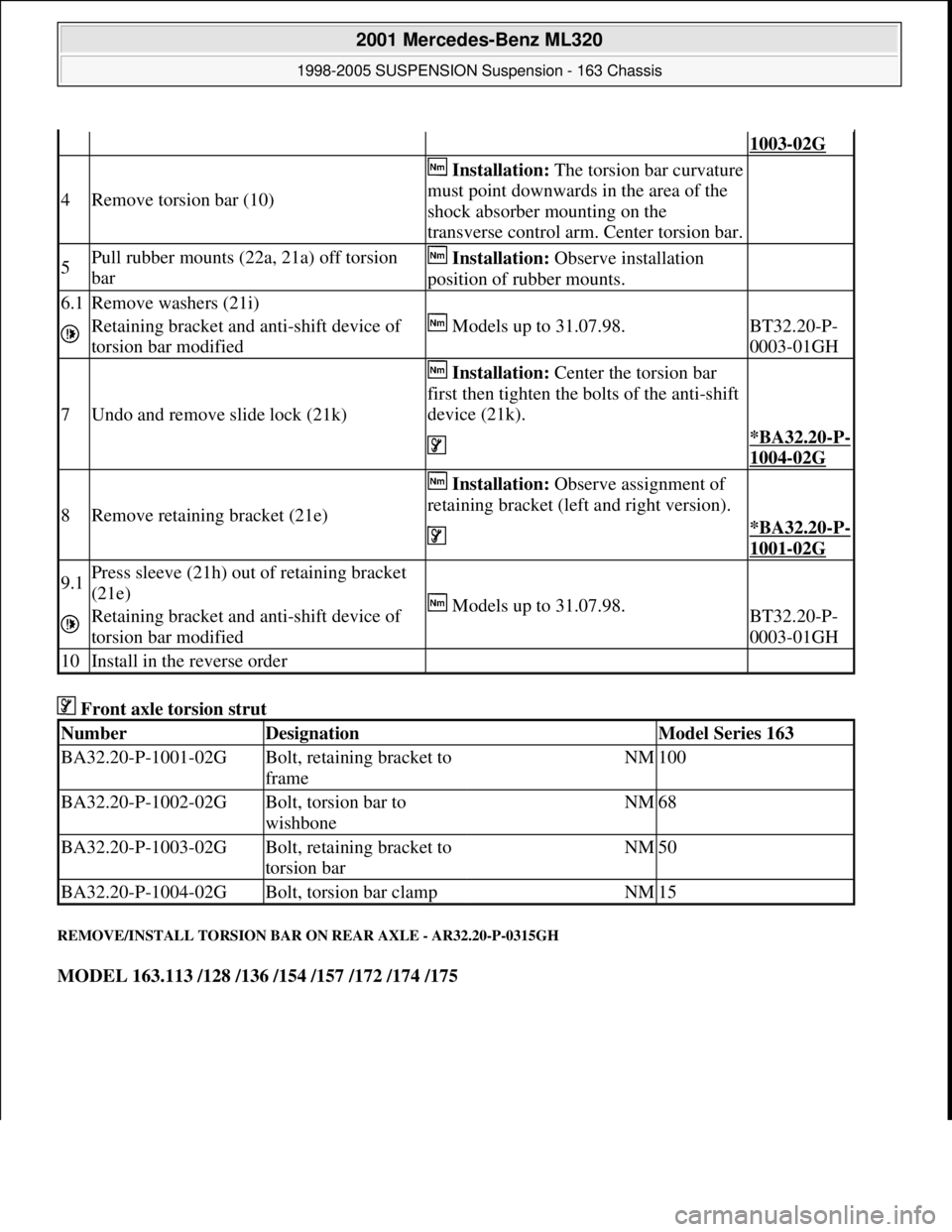
Front axle torsion strut
REMOVE/INSTALL TORSION BAR ON REAR AXLE - AR32.20-P-0315GH
MODEL 163.113 /128 /136 /154 /157 /172 /174 /175
1003-02G
4Remove torsion bar (10)
Installation:The torsion bar curvature
must point downwards in the area of the
shock absorber mounting on the
transverse control arm. Center torsion bar.
5Pull rubber mounts (22a, 21a) off torsion
bar Installation: Observe installation
position of rubber mounts.
6.1Remove washers (21i)
Models up to 31.07.98.
Retaining bracket and anti-shift device of
torsion bar modifiedBT32.20-P-
0003-01GH
7Undo and remove slide lock (21k)
Installation: Center the torsion bar
first then tighten the bolts of the anti-shift
device (21k).
*BA32.20-P-
1004-02G
8Remove retaining bracket (21e)
Installation: Observe assignment of
retaining bracket (left and right version).
*BA32.20-P-
1001-02G
9.1Press sleeve (21h) out of retaining bracket
(21e)
Models up to 31.07.98.
Retaining bracket and anti-shift device of
torsion bar modifiedBT32.20-P-
0003-01GH
10Install in the reverse order
NumberDesignationModel Series 163
BA32.20-P-1001-02GBolt, retaining bracket to
frameNM100
BA32.20-P-1002-02GBolt, torsion bar to
wishboneNM68
BA32.20-P-1003-02GBolt, retaining bracket to
torsion barNM50
BA32.20-P-1004-02GBolt, torsion bar clampNM15
2001 Mercedes-Benz ML320
1998-2005 SUSPENSION Suspension - 163 Chassis
me
Saturday, October 02, 2010 3:37:35 PMPage 11 © 2006 Mitchell Repair Information Company, LLC.
Page 3920 of 4133
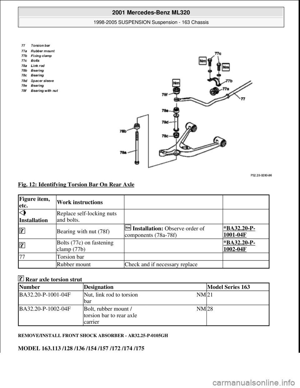
Fig. 12: Identifying Torsion Bar On Rear Axle
Rear axle torsion strut
REMOVE/INSTALL FRONT SHOCK ABSORBER - AR32.25-P-0105GH
MODEL 163.113 /128 /136 /154 /157 /172 /174 /175
Figure item,
etc.Work instructions
Installation Replace self-locking nuts
and bolts.
Bearing with nut (78f) Installation: Observe order of
components (78a-78f)*BA32.20-P-
1001-04F
Bolts (77c) on fastening
clamp (77b) *BA32.20-P-
1002-04F
77Torsion bar
Rubber mountCheck and if necessary replace
NumberDesignationModel Series 163
BA32.20-P-1001-04FNut, link rod to torsion
barNM21
BA32.20-P-1002-04FBolt, rubber mount /
torsion bar to rear axle
carrierNM28
2001 Mercedes-Benz ML320
1998-2005 SUSPENSION Suspension - 163 Chassis
me
Saturday, October 02, 2010 3:37:35 PMPage 12 © 2006 Mitchell Repair Information Company, LLC.
Page 3921 of 4133
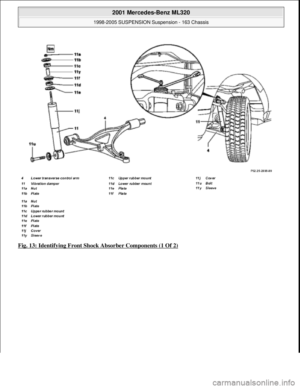
Fig. 13: Identifying Front Shock Absorber Components (1 Of 2)
2001 Mercedes-Benz ML320
1998-2005 SUSPENSION Suspension - 163 Chassis
me
Saturday, October 02, 2010 3:37:35 PMPage 13 © 2006 Mitchell Repair Information Company, LLC.
Page 3922 of 4133
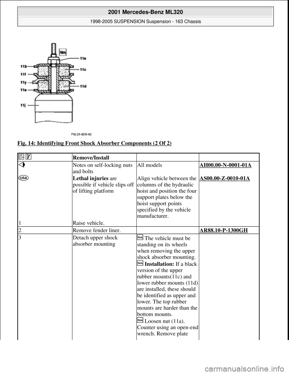
Fig. 14: Identifying Front Shock Absorber Components (2 Of 2)
Remove/Install
Notes on self-locking nuts
and boltsAll modelsAH00.00-N-0001-01A
Lethal injuries are
possible if vehicle slips off
of lifting platformAlign vehicle between the
columns of the hydraulic
hoist and position the four
support plates below the
hoist support points
specified by the vehicle
manufacturer.AS00.00-Z-0010-01A
1Raise vehicle.
2Remove fender liner. AR88.10-P-1300GH
3Detach upper shock
absorber mounting The vehicle must be
standing on its wheels
when removing the upper
shock absorber mounting.
Installation: If a black
version of the upper
rubber mounts(11c) and
lower rubber mounts (11d)
are installed, these should
be identified as upper and
lower. The top rubber
mounts are harder than the
bottom mounts.
Loosen nut (11a).
Counter using an open-end
wrench. Remove plate
2001 Mercedes-Benz ML320
1998-2005 SUSPENSION Suspension - 163 Chassis
me
Saturday, October 02, 2010 3:37:35 PMPage 14 © 2006 Mitchell Repair Information Company, LLC.
Page 3923 of 4133
Front axle shock absorber
REMOVE/INSTALL REAR SHOCK ABSORBER - AR32.25-P-0110GH
MODEL 163.113 /128 /136 /154 /157 /172 /174 /175
(11b), upper rubber mount
(11c), lower rubber mount
(11d), plate (11e) and
plate (11f).
Installation: If new
upper rubber mounts (11c)
and lower rubber mounts
(11d) are used, the white
coated (harder must be
installed at the top and the
yellow coated (softer)
must be installed at the
bottom. Observe the
sequence of the separate
parts and if necessary the
markings applied to the
upper rubber mount (11c)
and lower rubber mount
(11d).
*BA32.25-P-1002-01C
4Detach lower shock
absorber mounting from
lower transverse control
arm (4) Installation: Only
tighten bolt (11u) when
the vehicle is on its wheels
in the ready-to-drive
condition.
*BA32.25-P-1001-01C
5Remove shock absorber
(11)
6Shock absorber inspection Install new shock
absorber if necessary.AR32.25-P-0121A
Disposing of shock
absorber OS32.25-P-0121-01GH
7Install in the reverse order
NumberDesignationModel Series
163
BA32.25-P-1001-
01CBolt, shock absorber to lower wishboneNM130
BA32.25-P-1002-
01CSelf-locking nut, shock absorber to longitudinal frame
memberNM30
2001 Mercedes-Benz ML320
1998-2005 SUSPENSION Suspension - 163 Chassis
me
Saturday, October 02, 2010 3:37:35 PMPage 15 © 2006 Mitchell Repair Information Company, LLC.