MERCEDES-BENZ ML350 1997 Complete Repair Manual
Manufacturer: MERCEDES-BENZ, Model Year: 1997, Model line: ML350, Model: MERCEDES-BENZ ML350 1997Pages: 4133, PDF Size: 88.89 MB
Page 3371 of 4133
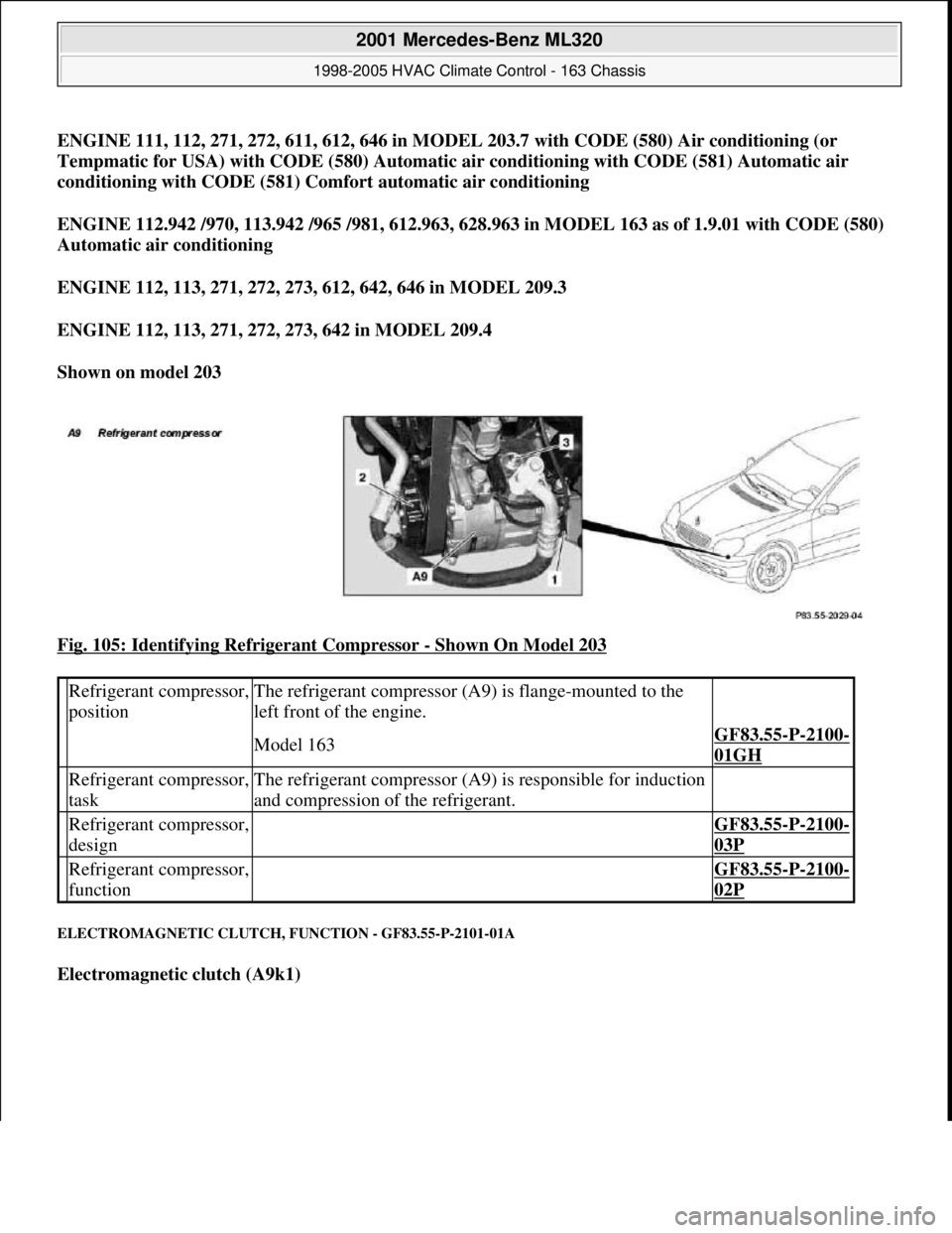
ENGINE 111, 112, 271, 272, 611, 612, 646 in MODEL 203.7 with CODE (580) Air conditioning (or
Tempmatic for USA) with CODE (580) Automatic air conditioning with CODE (581) Automatic air
conditioning with CODE (581) Comfort automatic air conditioning
ENGINE 112.942 /970, 113.942 /965 /981, 612.963, 628.963 in MODEL 163 as of 1.9.01 with CODE (580)
Automatic air conditioning
ENGINE 112, 113, 271, 272, 273, 612, 642, 646 in MODEL 209.3
ENGINE 112, 113, 271, 272, 273, 642 in MODEL 209.4
Shown on model 203
Fig. 105: Identifying Refrigerant Compressor
- Shown On Model 203
ELECTROMAGNETIC CLUTCH, FUNCTION - GF83.55-P-2101-01A
Electromagnetic clutch (A9k1)
Refrigerant compressor,
positionThe refrigerant compressor (A9) is flange-mounted to the
left front of the engine.
Model 163GF83.55-P-2100-
01GH
Refrigerant compressor,
taskThe refrigerant compressor (A9) is responsible for induction
and compression of the refrigerant.
Refrigerant compressor,
design GF83.55-P-2100-
03P
Refrigerant compressor,
function GF83.55-P-2100-
02P
2001 Mercedes-Benz ML320
1998-2005 HVAC Climate Control - 163 Chassis
me
Saturday, October 02, 2010 3:23:16 PMPage 127 © 2006 Mitchell Repair Information Company, LLC.
Page 3372 of 4133
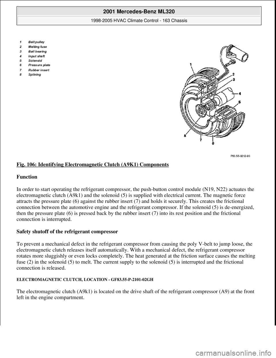
Fig. 106: Identifying Electromagnetic Clutch (A9K1) Components
Function
In order to start operating the refrigerant compressor, the push-button control module (N19, N22) actuates the
electromagnetic clutch (A9k1) and the solenoid (5) is supplied with electrical current. The magnetic force
attracts the pressure plate (6) against the rubber insert (7) and holds it securely. This creates the frictional
connection between the automotive engine and the refrigerant compressor. If the solenoid (5) is de-energized,
then the pressure plate (6) is pressed back by the rubber insert (7) into its rest position and the frictional
connection is interrupted.
Safety shutoff of the refrigerant compressor
To prevent a mechanical defect in the refrigerant compressor from causing the poly V-belt to jump loose, the
electromagnetic clutch releases itself automatically. With a mechanical defect, the refrigerant compressor
rotates more sluggishly or even locks completely. The heat generated at the friction surface causes the melting
fuse (2) in the solenoid (5) to melt. The current supply to the solenoid (5) is interrupted and the frictional
connection is released.
ELECTROMAGNETIC CLUTCH, LOCATION - GF83.55-P-2101-02GH
The electromagnetic clutch (A9k1) is located on the drive shaft of the refrigerant compressor (A9) at the front
left in the en
gine compartment.
2001 Mercedes-Benz ML320
1998-2005 HVAC Climate Control - 163 Chassis
me
Saturday, October 02, 2010 3:23:16 PMPage 128 © 2006 Mitchell Repair Information Company, LLC.
Page 3373 of 4133
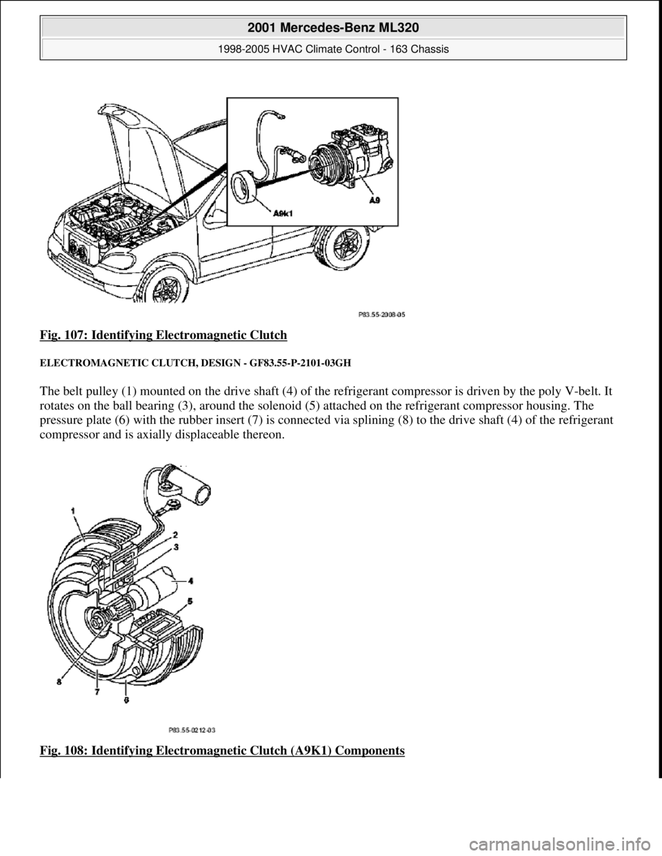
Fig. 107: Identifying Electromagnetic Clutch
ELECTROMAGNETIC CLUTCH, DESIGN - GF83.55-P-2101-03GH
The belt pulley (1) mounted on the drive shaft (4) of the refrigerant compressor is driven by the poly V-belt. It
rotates on the ball bearing (3), around the solenoid (5 ) attached on the refrigerant compressor housing. The
pressure plate (6) with the rubber insert (7) is connected via splining (8) to the drive shaft (4) of the refrigerant
compressor and is axially displaceable thereon.
Fig. 108: Identifying Electromagnet ic Clutch (A9K1) Components
2001 Mercedes-Benz ML320
1998-2005 HVAC Climate Control - 163 Chassis
me
Saturday, October 02, 2010 3:23:16 PMPage 129 © 2006 Mitchell Repair Information Company, LLC.
Page 3374 of 4133
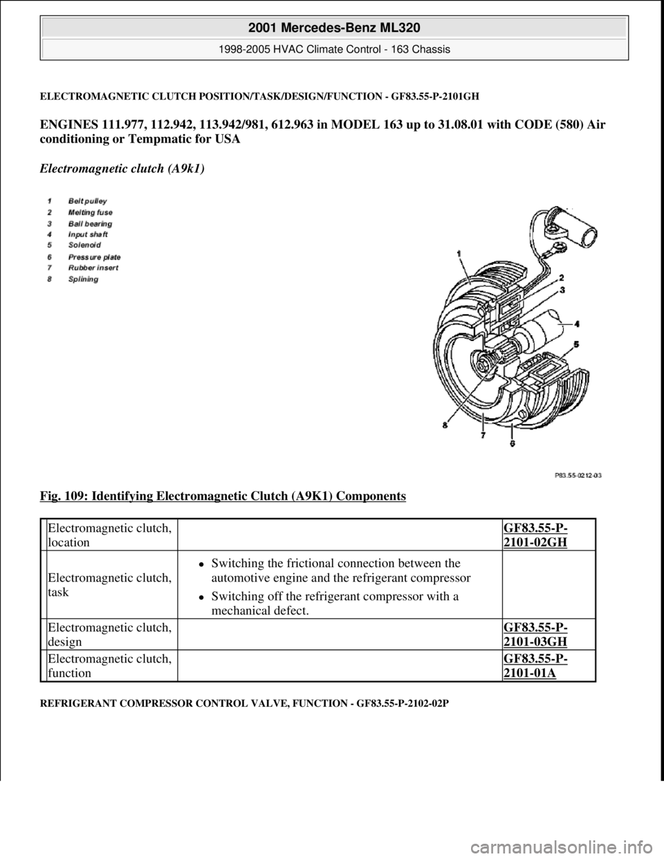
ELECTROMAGNETIC CLUTCH POSITION/TASK/DESIGN/FUNCTION - GF83.55-P-2101GH
ENGINES 111.977, 112.942, 113.942/981, 612.963 in MODEL 163 up to 31.08.01 with CODE (580) Air
conditioning or Tempmatic for USA
Electromagnetic clutch (A9k1)
Fig. 109: Identifying Electromagnetic Clutch (A9K1) Components
REFRIGERANT COMPRESSOR CONTROL VALVE, FUNCTION - GF83.55-P-2102-02P
Electromagnetic clutch,
location GF83.55-P-
2101-02GH
Electromagnetic clutch,
task
Switching the frictional connection between the
automotive engine and the refrigerant compressor
Switching off the refrigerant compressor with a
mechanical defect.
Electromagnetic clutch,
design GF83.55-P-
2101-03GH
Electromagnetic clutch,
function GF83.55-P-
2101-01A
2001 Mercedes-Benz ML320
1998-2005 HVAC Climate Control - 163 Chassis
me
Saturday, October 02, 2010 3:23:16 PMPage 130 © 2006 Mitchell Repair Information Company, LLC.
Page 3375 of 4133
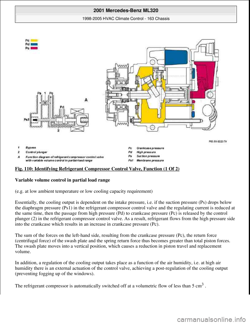
Fig. 110: Identifying Refrigerant Compressor Control Valve, Function (1 Of 2)
Variable volume control in partial load range
(e.g. at low ambient temperature or low cooling capacity requirement)
Essentially, the cooling output is dependent on the intake pressure, i.e. if the suction pressure (Ps) drops below
the diaphragm pressure (Ps1) in the refrigerant compressor control valve and the regulating current is reduced at
the same time, then the passage from high pressure (Pd) to crankcase pressure (Pc) is released by the control
plunger (2) in the refrigerant compressor control valve. As a result, refrigerant flows from the high pressure side
into the crankcase which results in an increase in crankcase pressure (Pc).
The sum of the forces on the left-hand side, resulting from the crankcase pressure (Pc), the return force
(centrifugal force) of the swash plate and the spring return force thus becomes greater than total piston forces.
The swash plate moves into a vertical position, which causes a reduction in piston travel and replacement
volume.
In addition, a regulation of the cooling output takes place as a function of the air humidity, i.e. at high air
humidity there is an external actuation of the control valve, achieving a post-regulation of the cooling output
(preventing fogging up of the windows).
The refrigerant compressor is automatically switched off at a volumetric flow of less than 5 cm
3.
2001 Mercedes-Benz ML320
1998-2005 HVAC Climate Control - 163 Chassis
me
Saturday, October 02, 2010 3:23:16 PMPage 131 © 2006 Mitchell Repair Information Company, LLC.
Page 3376 of 4133
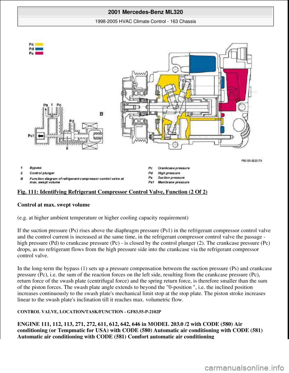
Fig. 111: Identifying Refrigerant Compressor Control Valve, Function (2 Of 2)
Control at max. swept volume
(e.g. at higher ambient temperature or higher cooling capacity requirement)
If the suction pressure (Ps) rises above the diaphragm pressure (Ps1) in the refrigerant compressor control valve
and the control current is increased at the same time, in the refrigerant compressor control valve the passage -
high pressure (Pd) to crankcase pressure (Pc) - is closed by the control plunger (2). The crankcase pressure (Pc)
drops, as no refrigerant flows from the high pressure side into the crankcase via the refrigerant compressor
control valve.
In the long-term the bypass (1) sets up a pressure compensation between the suction pressure (Ps) and crankcase
pressure (Pc), i.e. the sum of the reaction forces on the left side, resulting from the crankcase pressure (Pc),
return force of the swash plate (centrifugal force) and the spring return force, is therefore smaller than the sum
of the piston forces. The swash plate angle extends to beyond the "0-position ", i.e. the inclined position
increases continuously to the swash plate's mechanical limit stop at the stop plate. The piston stroke increases
linear to the swash plate's inclination till it reaches max. volumetric flow.
CONTROL VALVE, LOCATION/TASK/FUNCTION - GF83.55-P-2102P
ENGINE 111, 112, 113, 271, 272, 611, 612, 642, 646 in MODEL 203.0 /2 with CODE (580) Air
conditioning (or Tempmatic for USA) with CODE (580) Automatic air conditioning with CODE (581)
Automatic air conditioning with CODE (581) Comfort automatic air conditioning
2001 Mercedes-Benz ML320
1998-2005 HVAC Climate Control - 163 Chassis
me
Saturday, October 02, 2010 3:23:17 PMPage 132 © 2006 Mitchell Repair Information Company, LLC.
Page 3377 of 4133
ENGINE 111, 112, 271, 272, 611, 612, 646 in MODEL 203.7 with CODE (580) Air conditioning (or
Tempmatic for USA) with CODE (580) Automatic air conditioning with CODE (581) Automatic air
conditioning with CODE (581) Comfort automatic air conditioning
ENGINE 112.942 /970, 113.942 /965 /981, 612.963, 628.963 in MODEL 163 as of 1.9.01 with CODE (580)
Automatic air conditioning
ENGINE 112, 113, 271, 272, 273, 612, 642, 646 in MODEL 209.3
ENGINE 112, 113, 271, 272, 273, 642 in MODEL 209.4
Shown on model 203
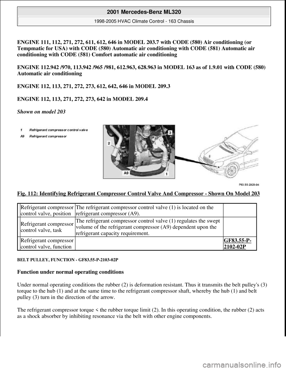
Fig. 112: Identifying Refrigerant Compressor Control Valve And Compressor
- Shown On Model 203
BELT PULLEY, FUNCTION - GF83.55-P-2103-02P
Function under normal operating conditions
Under normal operating conditions the rubber (2) is deformation resistant. Thus it transmits the belt pulley's (3)
torque to the hub (1) and at the same time to the refrigerant compressor shaft, whereby the hub (1) and belt
pulley (3) turn in the direction of the arrow.
The refrigerant compressor torque < the rubber torque limit (2). In this operating condition, the rubber (2) acts
as a shock absorber b
y inhibiting resonance via the belt with other engine components.
Refrigerant compressor
control valve, positionThe refrigerant compressor control valve (1) is located on the
refrigerant compressor (A9).
Refrigerant compressor
control valve, taskThe refrigerant compressor control valve (1) regulates the swept
volume of the refrigerant compressor (A9) dependent upon the
refrigerant capacity requirement.
Refrigerant compressor
control valve, function GF83.55-P-
2102-02P
2001 Mercedes-Benz ML320
1998-2005 HVAC Climate Control - 163 Chassis
me
Saturday, October 02, 2010 3:23:17 PMPage 133 © 2006 Mitchell Repair Information Company, LLC.
Page 3378 of 4133
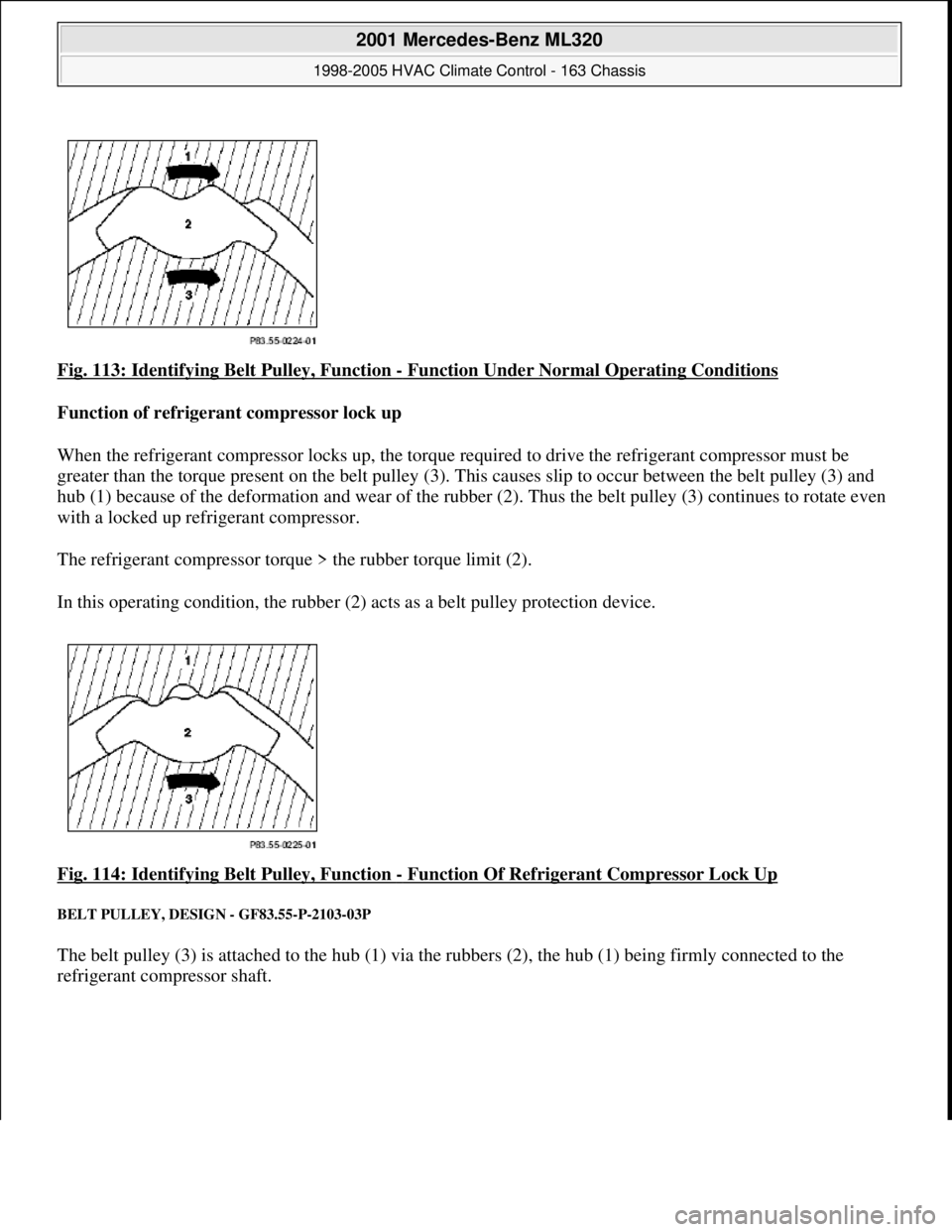
Fig. 113: Identifying Belt Pulley, Function - Function Under Normal Operating Conditions
Function of refrigerant compressor lock up
When the refrigerant compressor locks up, the torque re quired to drive the refrigerant compressor must be
greater than the torque present on the belt pulley (3). Th is causes slip to occur between the belt pulley (3) and
hub (1) because of the deformation and w ear of the rubber (2). Thus the belt pulley (3) continues to rotate even
with a locked up refrigerant compressor.
The refrigerant compressor torque > the rubber torque limit (2).
In this operating condition, the rubber (2) acts as a belt pulley protection device.
Fig. 114: Identifying Belt Pulley, Function
- Function Of Refrigerant Compressor Lock Up
BELT PULLEY, DESIGN - GF83.55-P-2103-03P
The belt pulley (3) is attached to the hub (1) via the rubbers (2), the hub (1) being firmly connected to the
refrigerant compressor shaft.
2001 Mercedes-Benz ML320
1998-2005 HVAC Climate Control - 163 Chassis
me
Saturday, October 02, 2010 3:23:17 PMPage 134 © 2006 Mitchell Repair Information Company, LLC.
Page 3379 of 4133
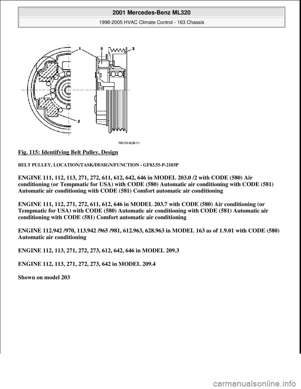
Fig. 115: Identifying Belt Pulley, Design
BELT PULLEY, LOCATION/TASK/DESIGN/FUNCTION - GF83.55-P-2103P
ENGINE 111, 112, 113, 271, 272, 611, 612, 642, 646 in MODEL 203.0 /2 with CODE (580) Air
conditioning (or Tempmatic for USA) with CODE (580) Automatic air conditioning with CODE (581)
Automatic air conditioning with CODE (581) Comfort automatic air conditioning
ENGINE 111, 112, 271, 272, 611, 612, 646 in MODEL 203.7 with CODE (580) Air conditioning (or
Tempmatic for USA) with CODE (580) Automatic air conditioning with CODE (581) Automatic air
conditioning with CODE (581) Comfort automatic air conditioning
ENGINE 112.942 /970, 113.942 /965 /981, 612.963, 628.963 in MODEL 163 as of 1.9.01 with CODE (580)
Automatic air conditioning
ENGINE 112, 113, 271, 272, 273, 612, 642, 646 in MODEL 209.3
ENGINE 112, 113, 271, 272, 273, 642 in MODEL 209.4
Shown on model 203
2001 Mercedes-Benz ML320
1998-2005 HVAC Climate Control - 163 Chassis
me
Saturday, October 02, 2010 3:23:17 PMPage 135 © 2006 Mitchell Repair Information Company, LLC.
Page 3380 of 4133
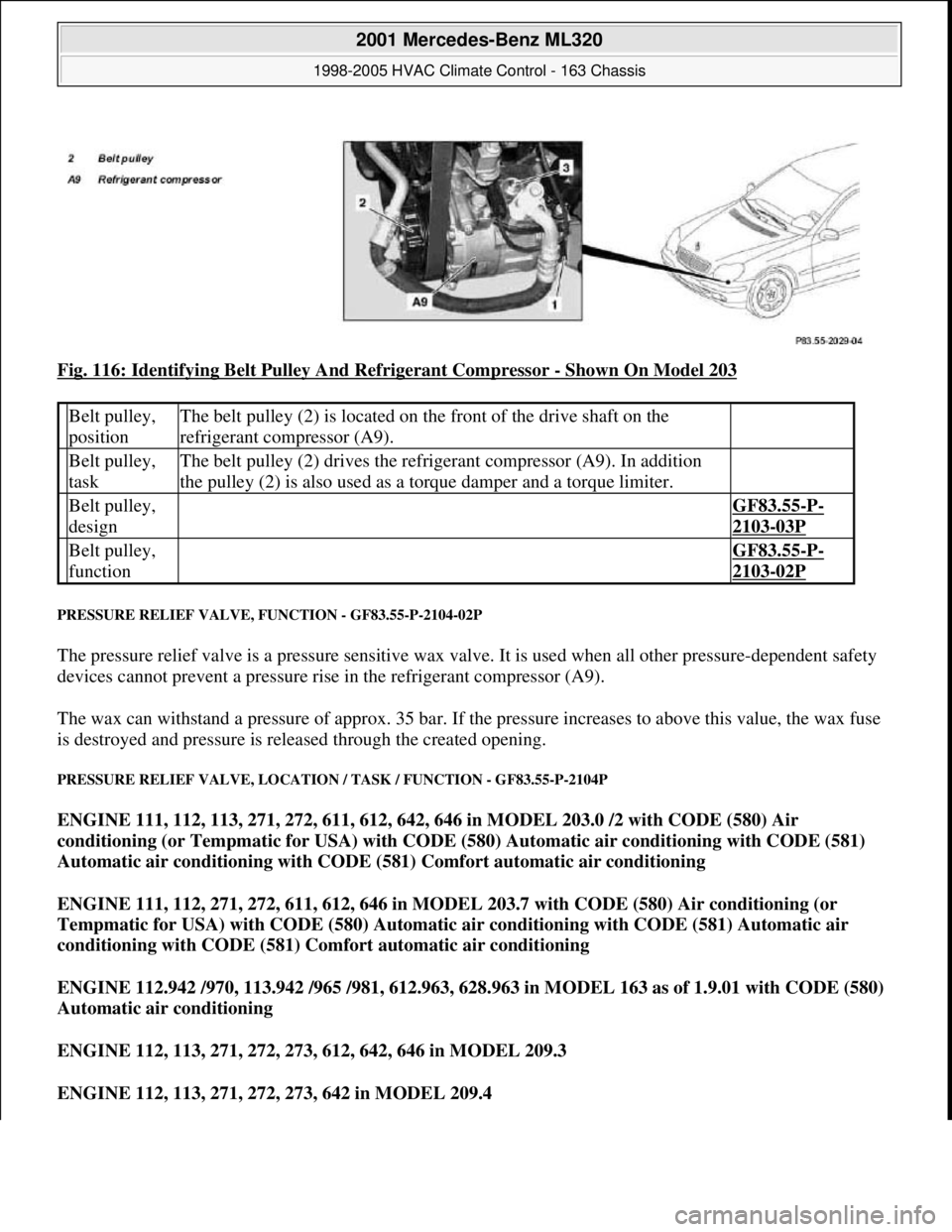
Fig. 116: Identifying Belt Pulley And Refrigerant Compressor - Shown On Model 203
PRESSURE RELIEF VALVE, FUNCTION - GF83.55-P-2104-02P
The pressure relief valve is a pressure sensitive wax valve. It is used when all other pressure-dependent safety
devices cannot prevent a pressure rise in the refrigerant compressor (A9).
The wax can withstand a pressure of approx. 35 bar. If the pressure increases to above this value, the wax fuse
is destroyed and pressure is released through the created opening.
PRESSURE RELIEF VALVE, LOCATION / TASK / FUNCTION - GF83.55-P-2104P
ENGINE 111, 112, 113, 271, 272, 611, 612, 642, 646 in MODEL 203.0 /2 with CODE (580) Air
conditioning (or Tempmatic for USA) with CODE (580) Automatic air conditioning with CODE (581)
Automatic air conditioning with CODE (581) Comfort automatic air conditioning
ENGINE 111, 112, 271, 272, 611, 612, 646 in MODEL 203.7 with CODE (580) Air conditioning (or
Tempmatic for USA) with CODE (580) Automatic air conditioning with CODE (581) Automatic air
conditioning with CODE (581) Comfort automatic air conditioning
ENGINE 112.942 /970, 113.942 /965 /981, 612.963, 628.963 in MODEL 163 as of 1.9.01 with CODE (580)
Automatic air conditioning
ENGINE 112, 113, 271, 272, 273, 612, 642, 646 in MODEL 209.3
ENGINE 112, 113, 271, 272, 273, 642 in MODEL 209.4
Belt pulley,
positionThe belt pulley (2) is located on the front of the drive shaft on the
refrigerant compressor (A9).
Belt pulley,
taskThe belt pulley (2) drives the refrigerant compressor (A9). In addition
the pulley (2) is also used as a torque damper and a torque limiter.
Belt pulley,
design GF83.55-P-
2103-03P
Belt pulley,
function GF83.55-P-
2103-02P
2001 Mercedes-Benz ML320
1998-2005 HVAC Climate Control - 163 Chassis
me
Saturday, October 02, 2010 3:23:17 PMPage 136 © 2006 Mitchell Repair Information Company, LLC.