MERCEDES-BENZ ML350 1997 Complete Repair Manual
Manufacturer: MERCEDES-BENZ, Model Year: 1997, Model line: ML350, Model: MERCEDES-BENZ ML350 1997Pages: 4133, PDF Size: 88.89 MB
Page 3781 of 4133

B6 688 0819 Adapter kit for fender flares, bordeaux red1B6 688 0820 Adapter kit for fender flares, alabaster white1B6 688 0821 Adapter kit for fender flares, black opal1
B6 688 0822 Adapter kit for fender flares, tansanite blue1B6 688 0823 Adapter kit for fender flares, jaspis blue1
B6 688 0824 Adapter kit for fender flares, desert silver1B6 688 0825 Adapter kit for fender flares, andradite green1
az8830p0007ghRetrofit fender flares Page 3 of 3
Page 3782 of 4133
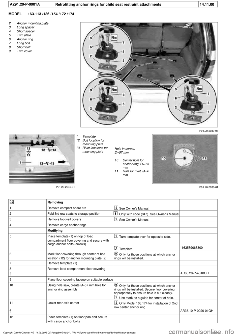
AZ91.20-P-0001A
Retrofitting anchor rings for child seat restraint attachments
14.11.00
MODEL
163.113 /136 /154 /172 /174
P91.20-2039-06
2
Anchor mounting plate
3
Long spacer
4
Short spacer
5
Trim plate
6
Anchor ring
7
Long bolt
8
Short bolt
9
Trim cover
P91.20-2040-01
1
Template
12
Bolt location for
mounting plate
13
Rivet locations for
mounting plate
Hole in carpet,
Ø=57 mm
10
Center hole for
anchor ring, Ø=9.5
mm
11
Hole for rivet, Ø=4
mm
P91.20-2038-01
Removing
1
Remove compact spare tire
See Owner's Manual.
2
Fold 3rd row seats to storage position
Only with code (847). See Owner's Manual.
3
Remove footwell covers
See Owner's Manual.
4
Remove cargo anchor rings
Modifying
5
Place template (1) on top of load
compartment floor covering and secure with
cargo anchor bolts (arrows)
Turn template over for opposite side.
Template
*163589066300
6
Mark floor covering through center of bolt
location (12) for anchor mounting plate (2)
Only for those positions at which anchor
rings will be installed.
7
Remove template (1)
8
Remove load compartment floor covering
f
AR68.20-P-4810GH
9
Place floor covering faceup on suitable surface
10
Using hole saw, create Ø=57 mm hole for
anchor ring assembly
Only for those positions at which anchor
rings will be installed. Secure floor covering
appropriately to ensure hole is cut cleanly.
Use mark as a guide for center of hole.
11
Lower rear axle carrier
Only Model 163.174 for installation of 2nd
row center anchor ring.
f
AR35.10-P-0020-01GH
12
Place template (1) on floor pan and secure
with cargo anchor bolts
Copyright DaimlerChrysler AG 14.06.2006 CD-Ausgabe G/10/04 . This WIS print-out will not be recorde
d by Modification services.
Page 1
Page 3783 of 4133
13
Mark floor pan through center of rivet and bolt
locations (12, 13) for anchor mounting plate (2)
Only for those positions at which anchor
rings will be installed.
14
Remove template (1)
15
At marks, drill Ø=9.5 mm hole (10) for anchor
bolt and Ø=4 mm holes (11) for rivets
Model 163.174: To avoid damaging
auxiliary fuel tank, do not drill more than 5mm
through floor pan for 2nd row center anchor
ring.
16
Smooth rough edges of holes on underside of
floor pan
17
Clean, prime, and paint holes
18
Using an assistant, place mounting plate (2)
into position from underneath vehicle and
secure with bolt (8)
Plate should be flush with surface of body.
19
Rivet plate into position from inside vehicle,
then remove bolt (8)
20
Seal underbody at plate location
Body seam sealant
*BR00.45-Z-1004-01A
Installing
21
Install load compartment floor covering
Do NOT install internal spare on Model
163.174 at this time.
f
AR68.20-P-4810GH
22
Loosely install trim plate (5) to observe fit to
floor covering
Straight edge of plate (5) towards front of
vehicle.
23
Remove trim plate (5) and relieve floor
covering so that plate, when installed, is
completely flush with floor covering
Use caution to avoid making hole too
large for trim plate to cover hole completely.
Square off hole at front. Relieve only down to
foam.
24
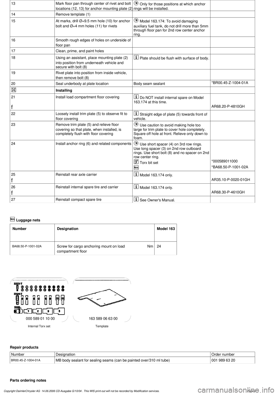
Install anchor ring (6) and related components
Use short spacer (4) on 3rd row rings.
Use long spacer (3) on 2nd row outboard
rings. Use short bolt (8) and no spacer on 2nd
row center ring.
Torx bit set
*000589011000
*BA68.50-P-1001-02A
25
Reinstall rear axle carrier
Model 163.174 only.
f
AR35.10-P-0020-01GH
26
Reinstall internal spare tire and carrier
Model 163.174 only.
f
AR68.30-P-4610GH
27
Reinstall compact spare tire
See Owner's Manual.
Luggage nets
Number
Designation
Model 163
BA68.50-P-1001-02A
Screw for cargo anchoring mount on load
compartment floor
Nm
24
163 589 06 63 00
Template
Internal Torx set
000 589 01 10 00
Repair products
Number
Designation
Order number
BR00.45-Z-1004-01A
MB body sealant for sealing seams (can be painted over/310 ml tube)
001 989 63 20
Parts ordering notes
Copyright DaimlerChrysler AG 14.06.2006 CD-Ausgabe G/10/04 . This WIS print-out will not be recorde
d by Modification services.
Page 2
Page 3784 of 4133

Part no.
Designation
Quantity
163 868 01 30 7C45
Trim cover
as needed
163 984 10 29
Short bolt (SAE) (for 2nd row center anchor ring only)
as needed
210 990 07 01
Long bolt (SAE)
as needed
000000 001427
Short bolt (metric) (for 2nd row center anchor ring only)
as needed
000000 001388
Long bolt (metric)
as needed
163 860 03 14 9051
Anchor ring
as needed
163 680 05 17
Trim plate
as needed
357 991 14 40
Short spacer (for 3rd row anchor rings only)
as needed
126 991 15 40
Long spacer (for 2nd row anchor rings, except center, only)
as needed
910002 004105
Rivet
as needed
124 984 04 25
Anchor mounting plate (SAE)
as needed
124 984 05 25
Anchor mounting plate (metric)
as needed
Copyright DaimlerChrysler AG 14.06.2006 CD-Ausgabe G/10/04 . This WIS print-out will not be recorde
d by Modification services.
Page 3
Page 3785 of 4133
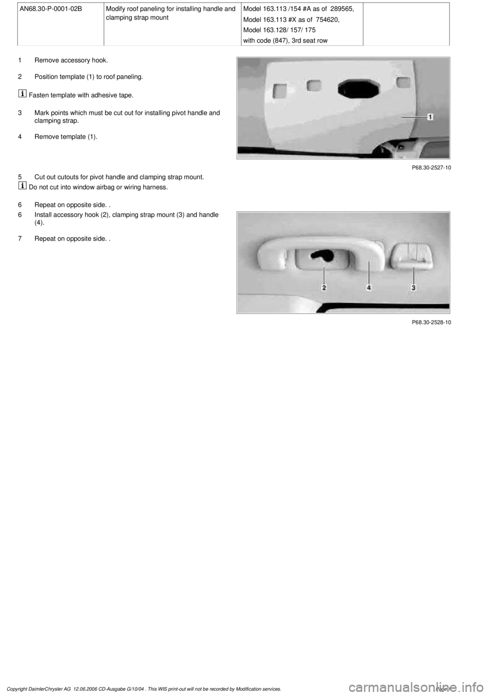
AN68.30-P-0001-02B
Modify roof paneling for installing handle and
clamping strap mount
Model 163.113 /154 #A as of 289565,
Model 163.113 #X as of 754620,
Model 163.128/ 157/ 175
with code (847), 3rd seat row
P68.30-2527-10
1
Remove accessory hook.
2
Position template (1) to roof paneling.
Fasten template with adhesive tape.
3
Mark points which must be cut out for installing pivot handle and
clamping strap.
4
Remove template (1).
5
Cut out cutouts for pivot handle and clamping strap mount.
Do not cut into window airbag or wiring harness.
6
Repeat on opposite side. .
P68.30-2528-10
6
Install accessory hook (2), clamping strap mount (3) and handle
(4).
7
Repeat on opposite side. .
Copyright DaimlerChrysler AG 12.06.2006 CD-Ausgabe G/10/04 . This WIS print-out will not be recorde
d by Modification services.
Page 1
Page 3786 of 4133
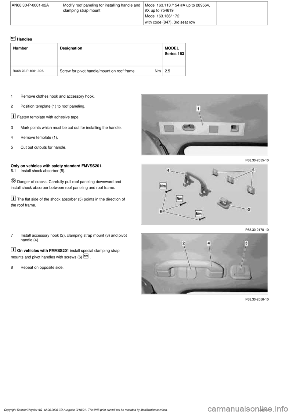
AN68.30-P-0001-02A
Modify roof paneling for installing handle and
clamping strap mount
Model 163.113 /154 #A up to 289564,
#X up to 754619
Model 163.136/ 172
with code (847), 3rd seat row
Handles
Number
Designation
MODEL
Series 163
BA68.70-P-1001-02A
Screw for pivot handle/mount on roof frame
Nm
2.5
P68.30-2055-10
1
Remove clothes hook and accessory hook.
2
Position template (1) to roof paneling.
Fasten template with adhesive tape.
3
Mark points which must be cut out for installing the handle.
4
Remove template (1).
5
Cut out cutouts for handle.
P68.30-2170-10
Only on vehicles with safety standard FMVSS201.
6.1
Install shock absorber (5).
Danger of cracks. Carefully pull roof paneling downward and
install shock absorber between roof paneling and roof frame.
The flat side of the shock absorber (5) points in the direction of
the roof frame.
P68.30-2056-10
7
Install accessory hook (2), clamping strap mount (3) and pivot
handle (4).
On vehicles with FMVSS201
install special clamping strap
mounts and pivot handles with screws (6)
.
8
Repeat on opposite side.
Copyright DaimlerChrysler AG 12.06.2006 CD-Ausgabe G/10/04 . This WIS print-out will not be recorde
d by Modification services.
Page 1
Page 3787 of 4133
AR46.40-P-0400GH
Check and replace rubber boot
12.3.97
MODEL
163.113 /128 /136 /154 /157 /172 /174 /175
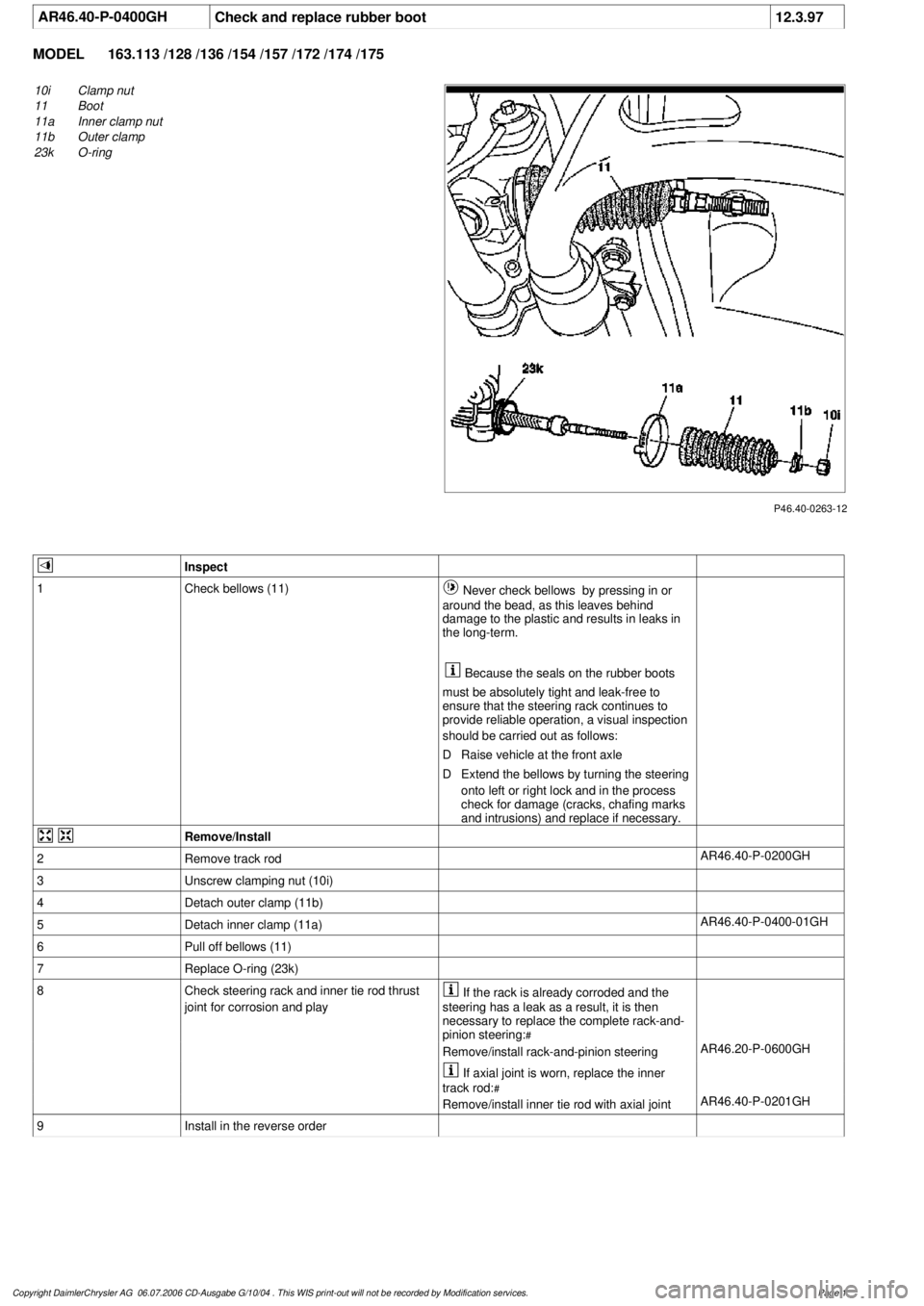
P46.40-0263-12
10i
Clamp nut
11
Boot
11a
Inner clamp nut
11b
Outer clamp
23k
O-ring
Inspect
1
Check bellows (11)
Never check bellows by pressing in or
around the bead, as this leaves behind
damage to the plastic and results in leaks in
the long-term.
Because the seals on the rubber boots
must be absolutely tight and leak-free to
ensure that the steering rack continues to
provide reliable operation, a visual inspection
should be carried out as follows:
D
Raise vehicle at the front axle
D
Extend the bellows by turning the steering
onto left or right lock and in the process
check for damage (cracks, chafing marks
and intrusions) and replace if necessary.
Remove/Install
2
Remove track rod
AR46.40-P-0200GH
3
Unscrew clamping nut (10i)
4
Detach outer clamp (11b)
5
Detach inner clamp (11a)
AR46.40-P-0400-01GH
6
Pull off bellows (11)
7
Replace O-ring (23k)
8
Check steering rack and inner tie rod thrust
joint for corrosion and play
If the rack is already corroded and the
steering has a leak as a result, it is then
necessary to replace the complete rack-and-
pinion steering:
#
Remove/install rack-and-pinion steering
AR46.20-P-0600GH
If axial joint is worn, replace the inner
track rod:
#
Remove/install inner tie rod with axial joint
AR46.40-P-0201GH
9
Install in the reverse order
Copyright DaimlerChrysler AG 06.07.2006 CD-Ausgabe G/10/04 . This WIS print-out will not be recorde
d by Modification services.
Page 1
Page 3788 of 4133
AF77.20-P-2005A
Seal on sliding/pop-up roof gutter loosens
28.6.00
MODEL
163.113 /136 /154 /172 /174 with CODE (414a) Electric glas sliding/pop-up roof
Modification notes
15.11.00
Damage code added
Damage code
Cause
Remedy
The seal on the sliding/pop-up roof loosens
when the sliding/pop-up roof moves
1
Remove sliding/pop-up roof
AR77.20-P-1000GH
2
Remove seal (1) from gutter (2)
3
Apply MB special glue along retaining
lip of gutter (arrows)
*BR00.45-Z-1003-02A
4
Install seal (1)
Allow MB special glue to dry before
installing sliding/-pop-up roof.
5
Install sliding/pop-up roof
AR77.20-P-1000GH
6
Adjust sliding/pop-up roof
AR77.20-P-1100GH
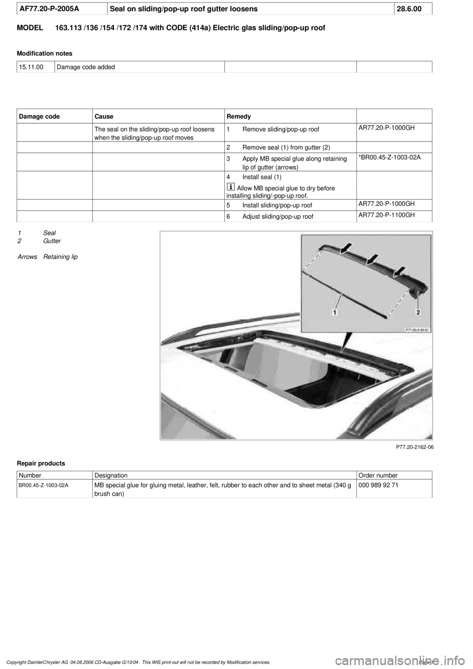
P77.20-2162-06
1
Seal
2
Gutter
Arrows
Retaining lip
Repair products
Number
Designation
Order number
BR00.45-Z-1003-02A
MB special glue for gluing metal, leather, felt, rubber to each other and to sheet metal (340 g
brush can)
000 989 92 71
Copyright DaimlerChrysler AG 04.08.2006 CD-Ausgabe G/10/04 . This WIS print-out will not be recorde
d by Modification services.
Page 1
Page 3789 of 4133
AR91.29-P-0008GH
Remove/install seat adjustment control module
23.6.99
MODEL
163.113 /128,
163.136 /154 as of 1.9.99,
163.157,
163.172 as of 1.9.99,
163.175
with CODE (241) Memory for electrically adjustable left front seat
with CODE (242a) Memory for electrically adjustable right front seat
MODEL
163.174
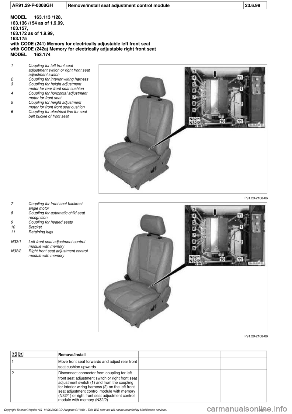
P91.29-2108-06
1
Coupling for left front seat
adjustment switch or right front seat
adjustment switch
2
Coupling for interior wiring harness
3
Coupling for height adjustment
motor for rear front seat cushion
4
Coupling for horizontal adjustment
motor for front seat
5
Coupling for height adjustment
motor for front front seat cushion
6
Coupling for electrical line for seat
belt buckle of front seat
P91.29-2108-06
7
Coupling for front seat backrest
angle motor
8
Coupling for automatic child seat
recognition
9
Coupling for heated seats
10
Bracket
11
Retaining lugs
N32/1
Left front seat adjustment control
module with memory
N32/2
Right front seat adjustment control
module with memory
Remove/Install
1
Move front seat forwards and adjust rear front
seat cushion upwards
2
Disconnect connector from coupling for left
front seat adjustment switch or right front seat
adjustment switch (1) and from the coupling
for interior wiring harness (2) on the left front
seat adjustment control module with memory
(N32/1) or right front seat adjustment control
module with memory (N32/2)
Copyright DaimlerChrysler AG 14.06.2006 CD-Ausgabe G/10/04 . This WIS print-out will not be recorde
d by Modification services.
Page 1
Page 3790 of 4133

3
Unscrew bolt (arrow) from bracket (10),
unhook front bracket and remove
4
Remove left front seat adjustment control
module with memory (N32/1) or right front
seat adjustment control module with memory
(N32/2) from bracket on front seat frame
Unhook two retaining lugs (11) on the side.
5
Disconnect the remaining connectors on the
left front seat adjustment control module with
memory (N32/1) or right front seat adjustment
control module with memory (N32/2)
6
Remove left front seat adjustment control
module with memory (N32/1) or right front
seat adjustment control module with memory
(N32/2)
7
Install in the reverse order
8
Perform function check
Copyright DaimlerChrysler AG 14.06.2006 CD-Ausgabe G/10/04 . This WIS print-out will not be recorde
d by Modification services.
Page 2