MERCEDES-BENZ ML350 1997 Complete Repair Manual
Manufacturer: MERCEDES-BENZ, Model Year: 1997, Model line: ML350, Model: MERCEDES-BENZ ML350 1997Pages: 4133, PDF Size: 88.89 MB
Page 3751 of 4133
GF54.30-P-3017A
Quartz, location/task/function
8.7.99
MODEL
129, 140 as of 1.6.96,
163, 168, 170,
202 as of 1.8.96,
208,
210 as of 1.6.96,
215, 220
P54.30-0519-01
Piezo-electric effect:
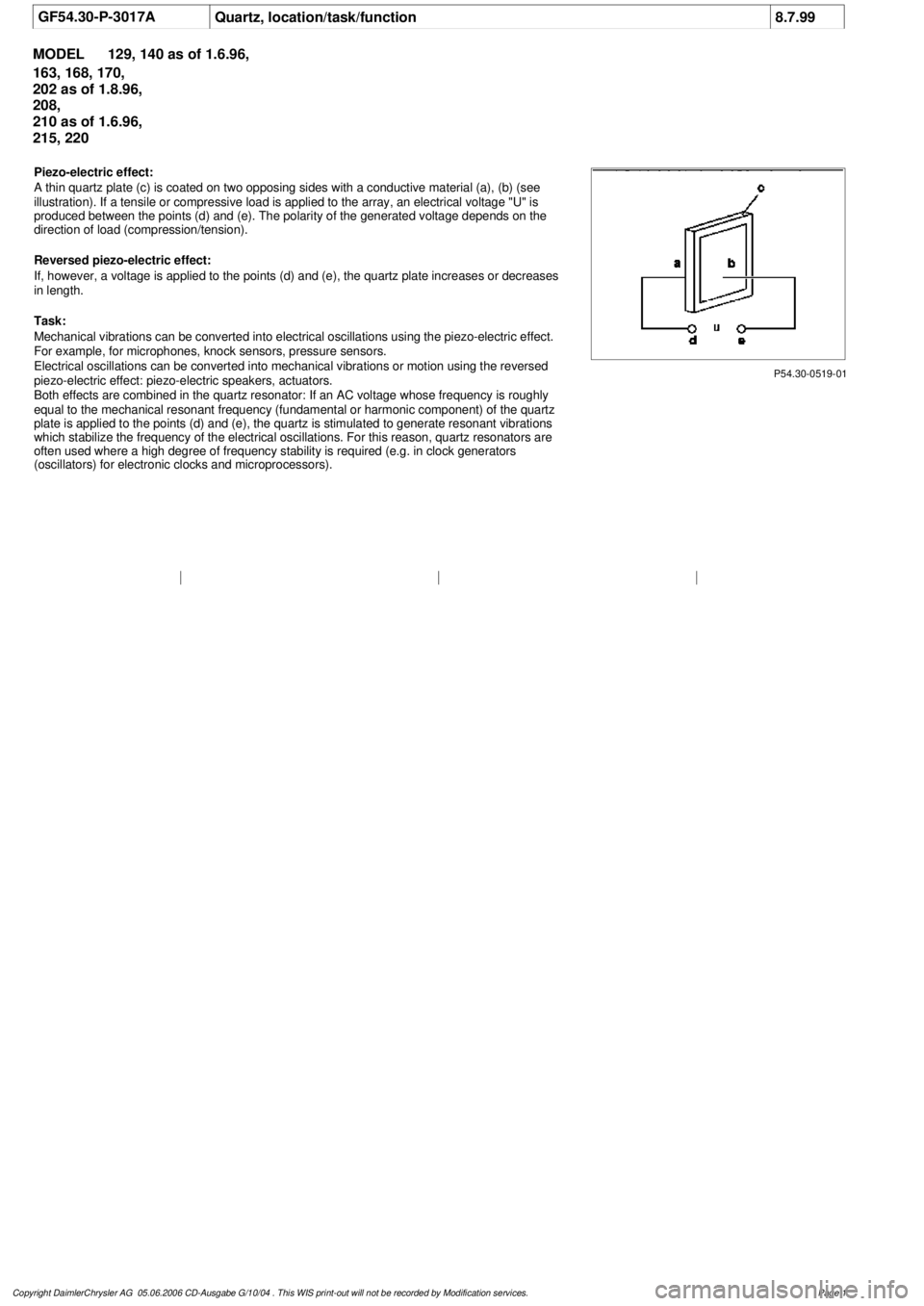
A thin quartz plate (c) is coated on two opposing sides with a conductive material (a), (b) (see
illustration). If a tensile or compressive load is applied to the array, an electrical voltage "U" i
s
produced between the points (d) and (e). The polarity of the generated voltage depends on the
direction of load (compression/tension).
Reversed piezo-electric effect:
If, however, a voltage is applied to the points (d) and (e), the quartz plate increases or decreases
in length.
Task:
Mechanical vibrations can be converted into electrical oscillations using the piezo-electric effect.
For example, for microphones, knock sensors, pressure sensors.
Electrical oscillations can be converted into mechanical vibrations or motion using the reversed
piezo-electric effect: piezo-electric speakers, actuators.
Both effects are combined in the quartz resonator: If an AC voltage whose frequency is roughly
equal to the mechanical resonant frequency (fundamental or harmonic component) of the quartz
plate is applied to the points (d) and (e), the quartz is stimulated to generate resonant vibrations
which stabilize the frequency of the electrical oscillations. For this reason, quartz resonators are
often used where a high degree of frequency stability is required (e.g. in clock generators
(oscillators) for electronic clocks and microprocessors).
Copyright DaimlerChrysler AG 05.06.2006 CD-Ausgabe G/10/04 . This WIS print-out will not be recorde
d by Modification services.
Page 1
Page 3752 of 4133
AR46.20-P-0600GH
Removing and installing rack-and-pinion steering
1.3.97
MODEL
163.113 /128 /136 /154 /157 /172 /174 /175
P46.20-2126-09
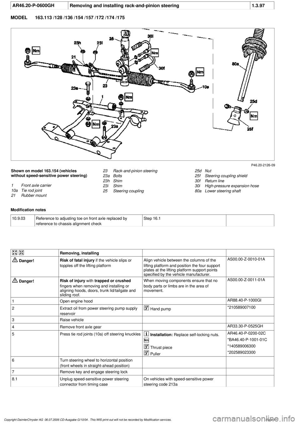
Shown on model 163.154 (vehicles
without speed-sensitive power steering)
1
Front axle carrier
10a
Tie rod joint
21
Rubber mount
25d
Nut
25f
Steering coupling shield
30f
Return line
30i
High-pressure expansion hose
80a
Lower steering shaft
23
Rack-and-pinion steering
23a
Bolts
23h
Shim
23i
Shim
25
Steering coupling
Modification notes
10.9.03
Reference to adjusting toe on front axle replaced by
reference to chassis alignment check
Step 16.1
Removing, installing
Danger!
Risk of fatal injury
if the vehicle slips or
topples off the lifting platform
Align vehicle between the columns of the
lifting platform and position the four support
plates
at the lifting platform support points
specified by the vehicle manufacturer.
AS00.00-Z-0010-01A
Danger!
Risk of injury
with
trapped or crushed
fingers when removing and installing or
aligning hoods, doors, trunk lid/tailgate and
sliding roof.
When moving components ensure that no
body parts or limbs are in the area of
movement.
AS00.00-Z-0011-01A
1
Open engine hood
AR88.40-P-1000GI
2
Extract oil from power steering pump supply
reservoir
Hand pump
*210589007100
3
Raise vehicle
4
Remove front axle gear
AR33.30-P-0525GH
5
Press tie rod joints (10a) off steering knuckles
Installation:
Replace self-locking nuts.
AR46.40-P-0200-02C
*BA46.40-P-1001-01C
Thrust piece
*140589006300
Puller
*202589023300
6
Turn steering wheel to horizontal position
(front wheels in straight-ahead position)
7
Remove key and engage steering lock
8.1
Unplug speed-sensitive power steering
connector from timing case
On vehicles with speed-sensitive power
steering code 213a
Copyright DaimlerChrysler AG 06.07.2006 CD-Ausgabe G/10/04 . This WIS print-out will not be recorde
d by Modification services.
Page 1
Page 3753 of 4133

9
Detach return line (30f) and high-pressure
expansion hose (30i)
Connection fittings or banjo bolts
depending on the version. Seal off line
connections with plugs.
Installation:
Replace sealing rings.
Connection fitting, return line
*BA46.20-P-1001-01D
Connection fitting, high-pressure
expansion hose
*BA46.20-P-1002-01D
Banjo bolt, return line
*BA46.20-P-1004-01D
Banjo bolt, high-pressure expansion hose
*BA46.20-P-1005-01D
Plug
*129589009100
10
Detach nut (25d) and bolt from steering
coupling (25) and pull lower steering shaft
(80a) upwards out of steering coupling (25)
Do not use force as the corrugated tube is
sensitive to lateral forces. Enlarge clamping
groove a little with a screwdriver if necessary.
Installation:
Replace nut (25d).
Installation:
Turn rack-and-pinion
steering to center position and fit steering
coupling.
AR46.20-P-0600-01GH
*BA46.10-P-1001-01D
11
Detach rack-and-pinion steering (23) from
front axle carrier (1) by unscrewing bolts (23a)
The installed position of the shims (23h,
23i) on the right-hand side, between the
rubber mount and the front axle carrier, must
be observed as the shims are of different
thicknesses.
Installation:
Attach rack-and-pinion
steering to front axle carrier.
AR46.20-P-0600-03GH
Assessing condition of steering gear when
repairing accident vehicles
AH46.20-P-9409-01A
12
Check rubber mount (21) of rack-and-pinion
steering mounting for damage
Replace rubber mount if necessary:
#
Removing rubber mounts on rack-and-pinion
steering mounting
AR46.20-P-0600-02GH
13
Install in the reverse order
14
Fill and bleed power steering pump
Engines 112, 113
AR46.30-P-0010B
Engines 111, 612, 628
AR46.30-P-0010P
15
Check steering for function and leaks
There is a grease cushion under the cover
cap. A small amount of escaping grease is to
be regarded as normal and must not be
confused with leakage.
16.1
Check toe on front axle and adjust if necessary
When installing a new rack-and-pinion
steering, see:
#
Performing chassis alignment check
AR40.20-P-0200A
Steering shaft
Number
Designation
Model 163
BA46.10-P-1001-01D
Self-locking nut, steering coupling to steering shaft
and rack-and-pinion steering
Nm
28
Steering gear
Number
Designation
Model 163
BA46.20-P-1001-01D
Screwed connection fitting from return line
to rack-and-pinion steering
Nm
15
BA46.20-P-1002-01D
Screwed connection fitting from high-
pressure expansion hose to rack-and-pinion
steering
Nm
15
BA46.20-P-1003-01D
Bolted connection, rack-and-pinion steering
to front axle carrierNm
50
BA46.20-P-1004-01D
Banjo bolt, return line to rack-and-pinion
steering
Nm
30
BA46.20-P-1005-01D
Banjo bolt, high-pressure expansion hose to
rack-and-pinion steering
Nm
30
Copyright DaimlerChrysler AG 06.07.2006 CD-Ausgabe G/10/04 . This WIS print-out will not be recorde
d by Modification services.
Page 2
Page 3754 of 4133
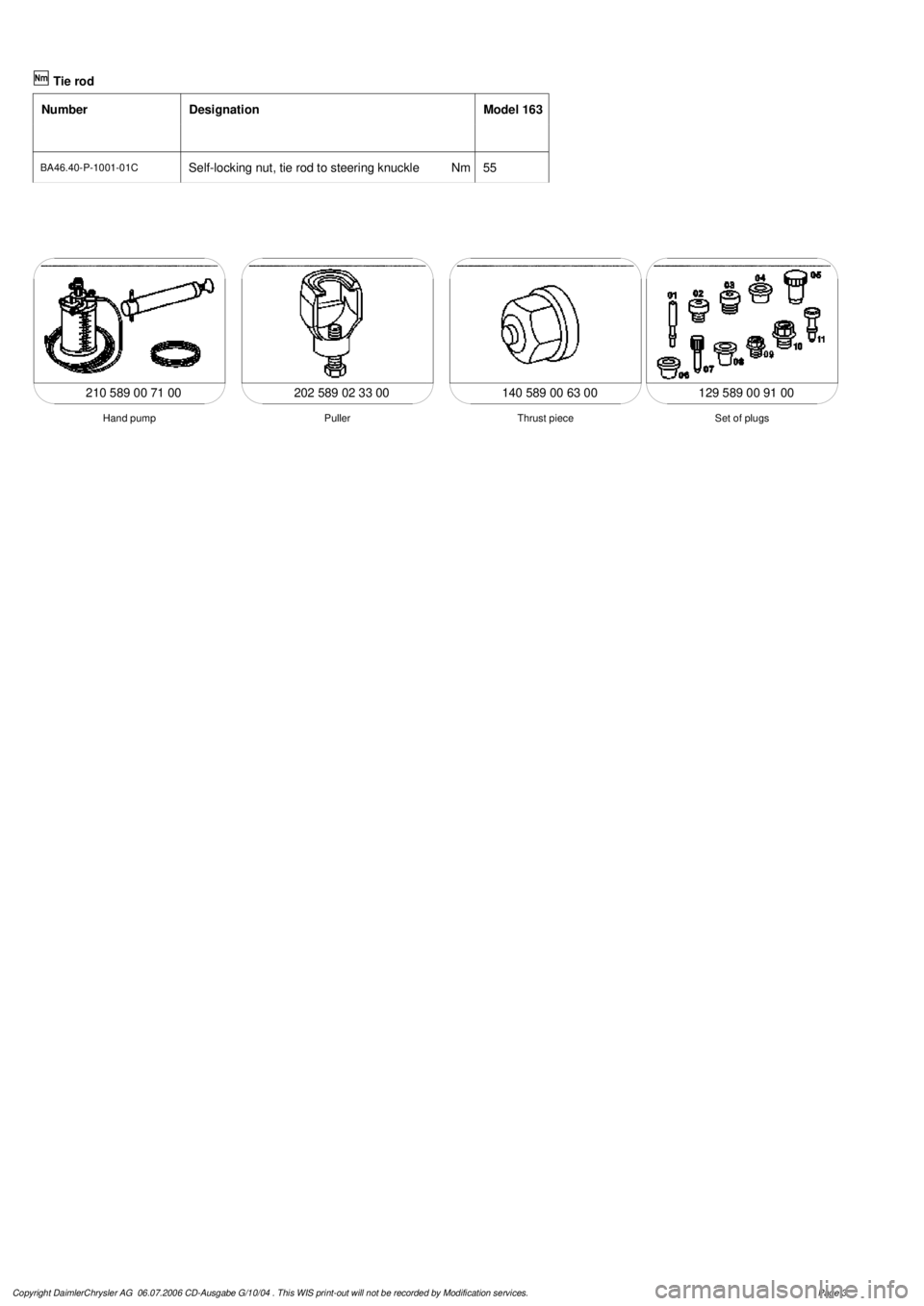
Tie rod
Number
Designation
Model 163
BA46.40-P-1001-01C
Self-locking nut, tie rod to steering knuckle
Nm
55
202 589 02 33 00
Thrust piece
Puller
Hand pump
210 589 00 71 00 140 589 00 63 00
Set of plugs
129 589 00 91 00
Copyright DaimlerChrysler AG 06.07.2006 CD-Ausgabe G/10/04 . This WIS print-out will not be recorde
d by Modification services.
Page 3
Page 3755 of 4133
AR20.40-P-5000GH
Remove/install electric fan
22.6.00
ENGINE
113.965 in MODEL 163.175
ENGINE
113.981 in MODEL 163.174
P20.40-2025-06
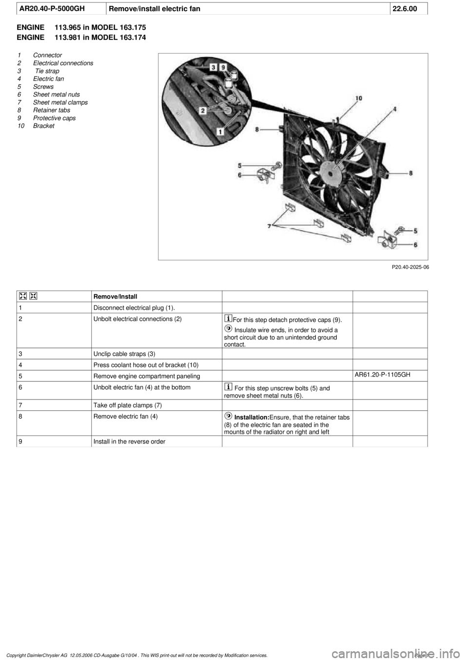
1
Connector
2
Electrical connections
3
Tie strap
4
Electric fan
5
Screws
6
Sheet metal nuts
7
Sheet metal clamps
8
Retainer tabs
9
Protective caps
10
Bracket
Remove/Install
1
Disconnect electrical plug (1).
2
Unbolt electrical connections (2)
For this step detach protective caps (9).
Insulate wire ends, in order to avoid a
short circuit due to an unintended ground
contact.
3
Unclip cable straps (3)
4
Press coolant hose out of bracket (10)
5
Remove engine compartment paneling
AR61.20-P-1105GH
6
Unbolt electric fan (4) at the bottom
For this step unscrew bolts (5) and
remove sheet metal nuts (6).
7
Take off plate clamps (7)
8
Remove electric fan (4)
Installation:
Ensure, that the retainer tabs
(8) of the electric fan are seated in the
mounts of the radiator on right and left
9
Install in the reverse order
Copyright DaimlerChrysler AG 12.05.2006 CD-Ausgabe G/10/04 . This WIS print-out will not be recorde
d by Modification services.
Page 1
Page 3756 of 4133
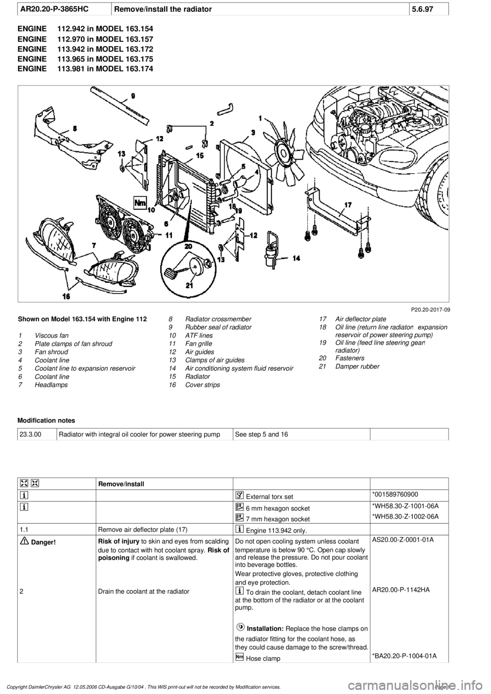
AR20.20-P-3865HC
Remove/install the radiator
5.6.97
ENGINE
112.942 in MODEL 163.154
ENGINE
112.970 in MODEL 163.157
ENGINE
113.942 in MODEL 163.172
ENGINE
113.965 in MODEL 163.175
ENGINE
113.981 in MODEL 163.174
P20.20-2017-09
Shown on Model 163.154 with Engine 112
1
Viscous fan
2
Plate clamps of fan shroud
3
Fan shroud
4
Coolant line
5
Coolant line to expansion reservoir
6
Coolant line
7
Headlamps
17
Air deflector plate
18
Oil line (return line radiator
!
expansion
reservoir of power steering pump)
19
Oil line (feed line steering gear
!
radiator)
20
Fasteners
21
Damper rubber
8
Radiator crossmember
9
Rubber seal of radiator
10
ATF lines
11
Fan grille
12
Air guides
13
Clamps of air guides
14
Air conditioning system fluid reservoir
15
Radiator
16
Cover strips
Modification notes
23.3.00
Radiator with integral oil cooler for power steering pump
See step 5 and 16
Remove/install
External torx set
*001589760900
6 mm hexagon socket
*WH58.30-Z-1001-06A
7 mm hexagon socket
*WH58.30-Z-1002-06A
1.1
Remove air deflector plate (17)
Engine 113.942 only.
Danger!
Risk of injury
to skin and eyes from scalding
due to contact with hot coolant spray.
Risk of
poisoning
if coolant is swallowed.
Do not open cooling system unless coolant
temperature is below 90 °C. Open cap slowly
and release the pressure. Do not pour coolant
into beverage bottles.
Wear protective gloves, protective clothing
and eye protection.
AS20.00-Z-0001-01A
2
Drain the coolant at the radiator
To drain the coolant, detach coolant line
at the bottom of the radiator or at the coolant
pump.
Installation:
Replace the hose clamps on
the radiator fitting for the coolant hose, as
they could cause damage to the screw/thread. AR20.00-P-1142HA
Hose clamp
*BA20.20-P-1004-01A
Copyright DaimlerChrysler AG 12.05.2006 CD-Ausgabe G/10/04 . This WIS print-out will not be recorde
d by Modification services.
Page 1
Page 3757 of 4133

3.1
Remove viscous fan (1)
Engine 112.942 /970 and 113.942.
Right-hand thread!
AR20.40-P-5660C
3.2
Remove electric fan
Only Engine 113.965 /981.
AR20.40-P-5000GH
4.1
Pull off plate clamps of fan shroud (2)
Only for Engine 112.942, from 5/98.
5.1
Remove fan shroud (3)
Only for Engine 112.942 /970 und
113.942. Unscrew the bolts at bottom of fan
shroud for this step
Installation:
If installing a new radiator
with integral power steering pump oil cooler, a
new fan shroud is required if a radiator
without integral oil cooler was previously
installed.
6
Remove headlamp (7).
AR82.10-P-4730GH
7
Remove radiator crossmember (8)
AR62.30-P-2300GH
8
Detach coolant line (4, 6) and expansion
reservoir coolant line (5) at the radiator
Installation:
Replace the hose clamps on
the radiator fitting for the coolant hose, as
they could cause damage to the screw/thread.
Hose clamp
*BA20.20-P-1004-01A
9
Remove the rubber seal on radiator (9)
10.1
Remove oil line (return line of radiator
!
power steering pump expansion reservoir)
(18) and oil line (feed line of steering gear
!
radiator) (19)
From 5/98 only, seal off the connections.
Set of plugs
*129589009100
11
Unscrew ATF lines (10) at the radiator
Seal off the connections.
*BA20.20-P-1001-01A
*BA20.20-P-1003-01A
Set of plugs
*129589009100
12.1
Detach the connector from the fan and
remove the fan grille (11)
Only for Engine 112.942 /970 and 113.942.
13
Unscrew the condenser from the radiator
Do not disconnect the lines.
14
Remove fasteners (20) and damper rubber
(21)
The damper rubber (21) is designed to
prevent possible vibrations between the
condenser and radiator (15) during off-road
driving.
15
Remove air conditioning system fluid
reservoir (14) from the radiator
Place aside with the lines connected.
Detach the condenser from the radiator.
16
Remove radiator (15)
When installing, the spigots on the
radiator must be inserted in the rubber
grommets in the bottom crossmember.
Installation:
On Model 163.154 with
Engine 112.942 before VIN end number
043553, when installing a new radiator with
integral power steering pump oil cooler,
additional operations are required, if they
have not already been carried out:
#
v
Retrofit the bracket for the oil cooler line of
the power steering pump
SM46.30-P-0002A
k
Radiator with integral oil cooler for the power
steering pump
BT20.20-P-0001-01A
17
Detach air guides (12)
Replace the clamps on air guides (13).
18
Install in the reverse order
19
Pour in coolant
AR20.00-P-1142HA
20
Check the headlamp setting and correct if
necessary
e
Check and adjust the headlamp setting
AP82.10-P-8260GH
Danger!
Risk of accident
caused by vehicle starting
off when engine is running.
Risk of injury
caused by contusions and burns when
working in engine during starting procedure
Secure the vehicle to prevent it from moving.
Wear closed and snug-fitting work clothes.
Do not grasp hot or rotating parts.
AS00.00-Z-0005-01A
21
Check the oil level in the automatic
transmission and correct if necessary
AR27.00-P-0101A
22
Check the cooling system for leaks
AR20.00-P-1010HA
Radiator, coolant hoses
Copyright DaimlerChrysler AG 12.05.2006 CD-Ausgabe G/10/04 . This WIS print-out will not be recorde
d by Modification services.
Page 2
Page 3758 of 4133
Number
Designation
Engine
112.942/
970,
113.942/
965/981
BA20.20-P-1001-01A
Union nut on automatic transmission
ATF line to radiatorNm
20
BA20.20-P-1003-01A
Banjo bolt
M12X1.5
Nm
30
BA20.20-P-1004-01A
Hose clamp
Nm
3
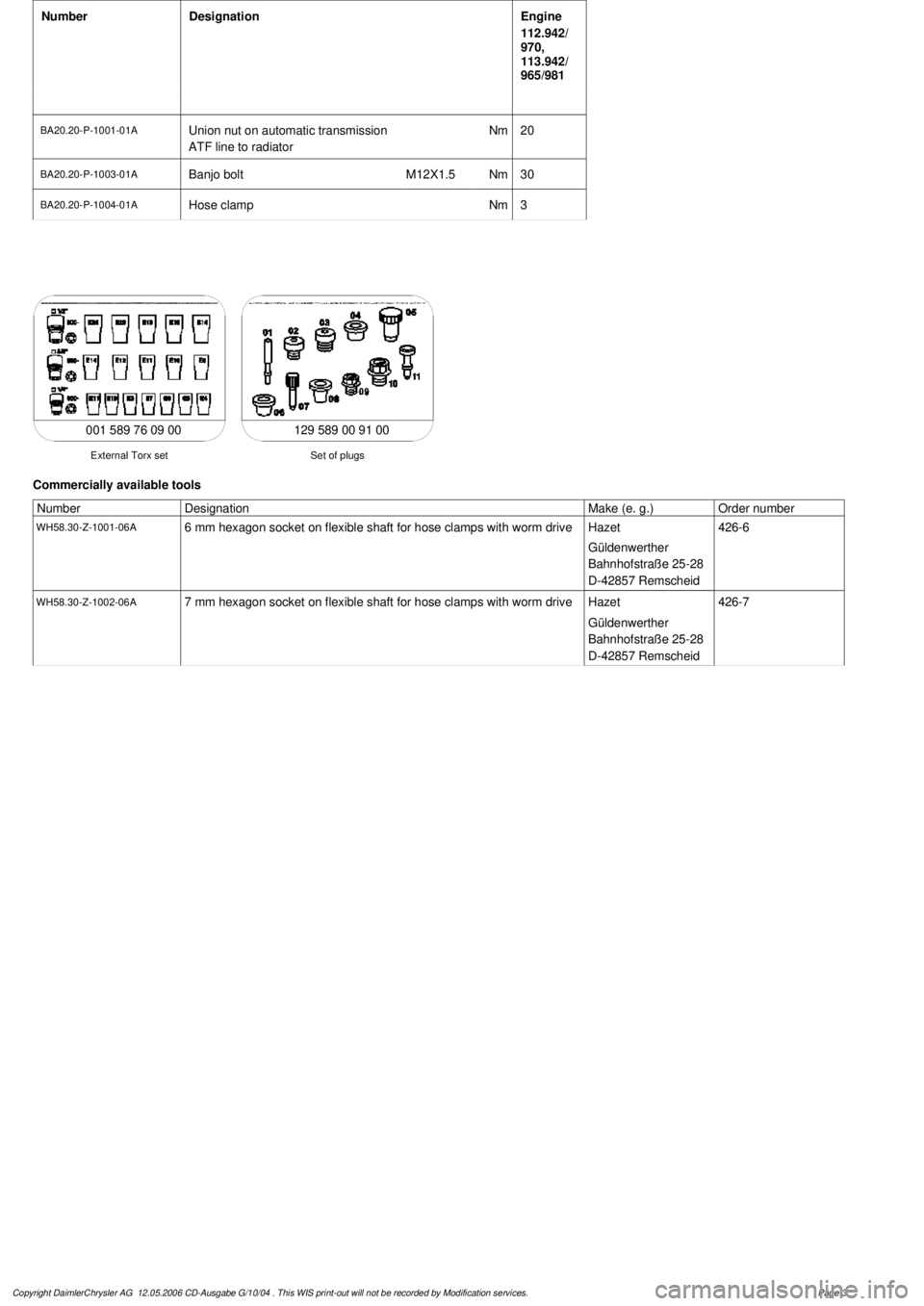
129 589 00 91 00
Set of plugs
External Torx set
001 589 76 09 00
Commercially available tools
Number
Designation
Make (e. g.)
Order number
WH58.30-Z-1001-06A
6 mm hexagon socket on flexible shaft for hose clamps with worm drive
Hazet
Güldenwerther
Bahnhofstraße 25-28
D-42857 Remscheid
426-6
WH58.30-Z-1002-06A
7 mm hexagon socket on flexible shaft for hose clamps with worm drive
Hazet
Güldenwerther
Bahnhofstraße 25-28
D-42857 Remscheid
426-7
Copyright DaimlerChrysler AG 12.05.2006 CD-Ausgabe G/10/04 . This WIS print-out will not be recorde
d by Modification services.
Page 3
Page 3759 of 4133
AR20.40-P-5000M
Remove/install electric fan
24.8.99
ENGINE
612.963 in MODEL 163.113
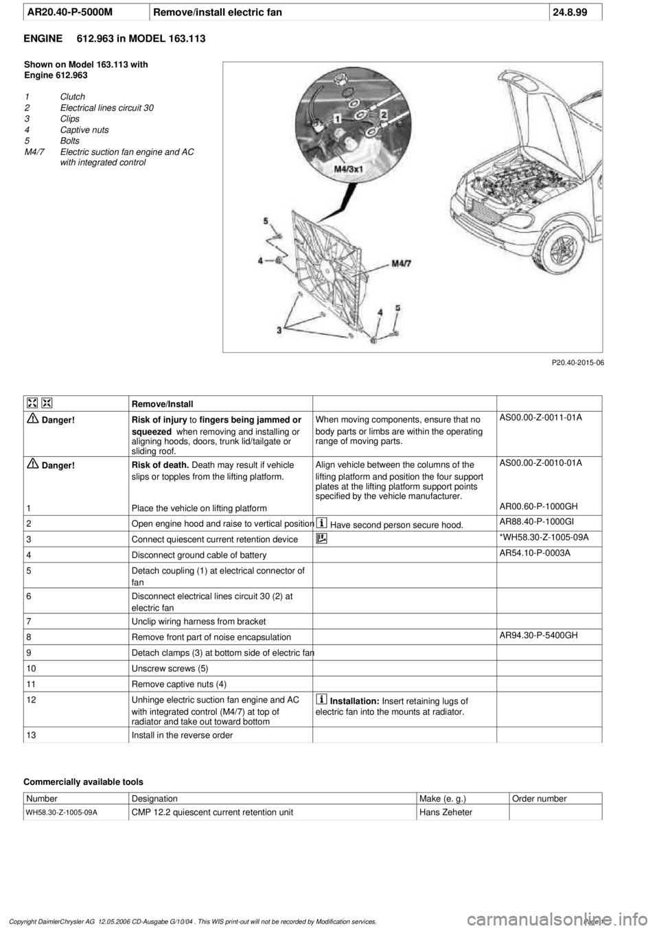
P20.40-2015-06
Shown on Model 163.113 with
Engine 612.963
1
Clutch
2
Electrical lines circuit 30
3
Clips
4
Captive nuts
5
Bolts
M4/7
Electric suction fan engine and AC
with integrated control
Remove/Install
Danger!
Risk of injury
to
fingers being jammed or
squeezed
when removing and installing or
aligning hoods, doors, trunk lid/tailgate or
sliding roof.
When moving components, ensure that no
body parts or limbs are within the operating
range of moving parts.
AS00.00-Z-0011-01A
Danger!
Risk of death.
Death may result if vehicle
slips or topples from the lifting platform.
Align vehicle between the columns of the
lifting platform and position the four support
plates
at the lifting platform support points
specified by the vehicle manufacturer.
AS00.00-Z-0010-01A
1
Place the vehicle on lifting platform
AR00.60-P-1000GH
2
Open engine hood and raise to vertical position
Have second person secure hood.
AR88.40-P-1000GI
3
Connect quiescent current retention device
*WH58.30-Z-1005-09A
4
Disconnect ground cable of battery
AR54.10-P-0003A
5
Detach coupling (1) at electrical connector of
fan
6
Disconnect electrical lines circuit 30 (2) at
electric fan
7
Unclip wiring harness from bracket
8
Remove front part of noise encapsulation
AR94.30-P-5400GH
9
Detach clamps (3) at bottom side of electric fan
10
Unscrew screws (5)
11
Remove captive nuts (4)
12
Unhinge electric suction fan engine and AC
with integrated control (M4/7) at top of
radiator and take out toward bottom
Installation:
Insert retaining lugs of
electric fan into the mounts at radiator.
13
Install in the reverse order
Commercially available tools
Number
Designation
Make (e. g.)
Order number
WH58.30-Z-1005-09A
CMP 12.2 quiescent current retention unit
Hans Zeheter
Copyright DaimlerChrysler AG 12.05.2006 CD-Ausgabe G/10/04 . This WIS print-out will not be recorde
d by Modification services.
Page 1
Page 3760 of 4133
AR20.20-P-3865MM
Remove/install radiator
10.11.99
ENGINE
612.963 in MODEL 163.113
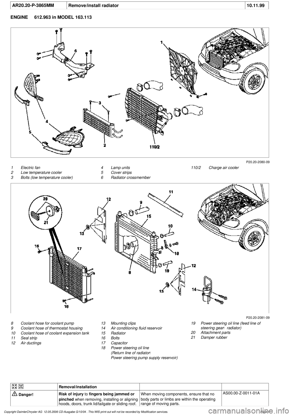
P20.20-2080-09
1
Electric fan
2
Low temperature cooler
3
Bolts (low temperature cooler)
110/2
Charge air cooler
4
Lamp units
5
Cover strips
6
Radiator crossmember
P20.20-2081-09
8
Coolant hose for coolant pump
9
Coolant hose of thermostat housing
10
Coolant hose of coolant expansion tank
11
Seal strip
12
Air ductings
19
Power steering oil line (feed line of
steering gear
!
radiator)
20
Attachment parts
21
Damper rubber
13
Mounting clips
14
Air conditioning fluid reservoir
15
Radiator
16
Bolts
17
Capacitor
18
Power steering oil line
(Return line of radiator
!
Power steering pump supply reservoir)
Removal/installation
Danger!
Risk of injury
to
fingers being jammed or
pinched
when removing, installing or aligning
hoods, doors, trunk lid/tailgate or sliding roof.
When moving components, ensure that no
body parts or limbs are within the operating
range of moving parts.
AS00.00-Z-0011-01A
Copyright DaimlerChrysler AG 12.05.2006 CD-Ausgabe G/10/04 . This WIS print-out will not be recorde
d by Modification services.
Page 1