MERCEDES-BENZ ML350 1997 Complete Repair Manual
Manufacturer: MERCEDES-BENZ, Model Year: 1997, Model line: ML350, Model: MERCEDES-BENZ ML350 1997Pages: 4133, PDF Size: 88.89 MB
Page 3931 of 4133
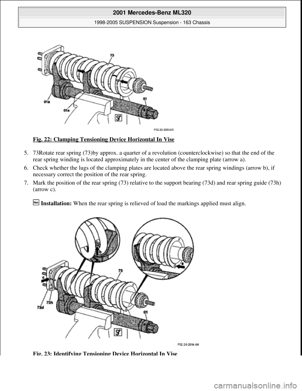
Fig. 22: Clamping Tensioning Device Horizontal In Vise
5. 73Rotate rear spring (73)by approx. a quarter of a revolution (counterclockwise) so that the end of the
rear spring winding is located approximately in the center of the clamping plate (arrow a).
6. Check whether the lugs of the clamping plates are located above the rear spring windings (arrow b), if
necessary correct the position of the rear spring.
7. Mark the position of the rear spring (73) relative to the support bearing (73d) and rear spring guide (73h)
(arrow c).
Installation: When the rear spring is relieved of load the markings applied must align.
Fig. 23: Identifying Tensioning Device Horizontal In Vise
2001 Mercedes-Benz ML320
1998-2005 SUSPENSION Suspension - 163 Chassis
me
Saturday, October 02, 2010 3:37:36 PMPage 23 © 2006 Mitchell Repair Information Company, LLC.
Page 3932 of 4133
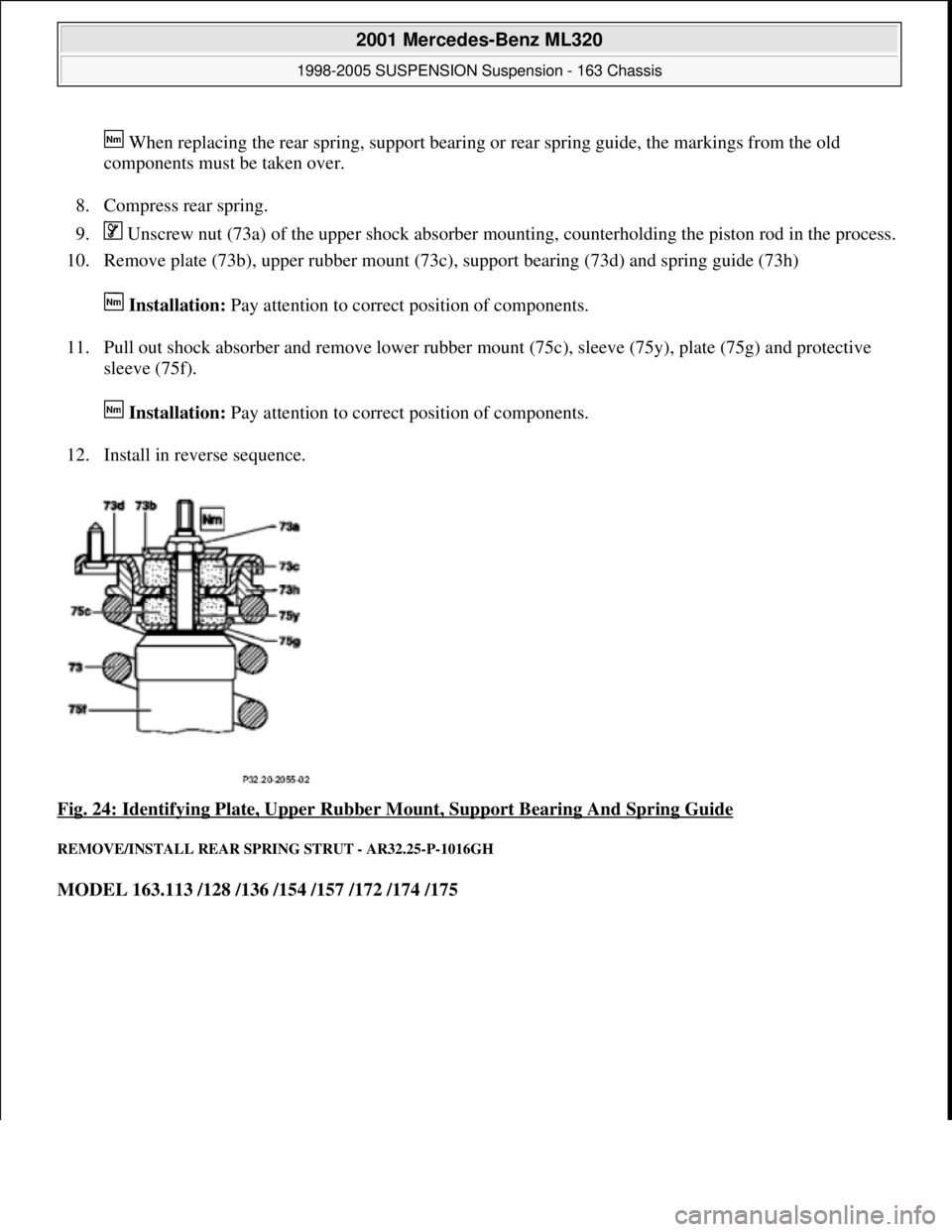
When replacing the rear spring, support bearing or rear spring guide, the markings from the old
components must be taken over.
8. Compress rear spring.
9. Unscrew nut (73a) of the upper shock absorber mounting, counterholding the piston rod in the process.
10. Remove plate (73b), upper rubber mount (73c), support bearing (73d) and spring guide (73h)
Installation: Pay attention to correct position of components.
11. Pull out shock absorber and remove lower rubber mount (75c), sleeve (75y), plate (75g) and protective
sleeve (75f).
Installation: Pay attention to correct position of components.
12. Install in reverse sequence.
Fig. 24: Identifying Plate, Upper Rubber Mount, Support Bearing And Spring Guide
REMOVE/INSTALL REAR SPRING STRUT - AR32.25-P-1016GH
MODEL 163.113 /128 /136 /154 /157 /172 /174 /175
2001 Mercedes-Benz ML320
1998-2005 SUSPENSION Suspension - 163 Chassis
me
Saturday, October 02, 2010 3:37:36 PMPage 24 © 2006 Mitchell Repair Information Company, LLC.
Page 3933 of 4133
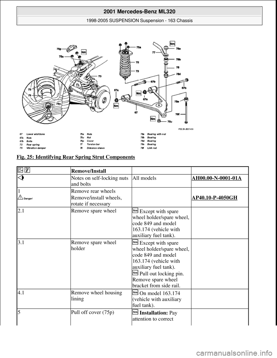
Fig. 25: Identifying Rear Spring Strut Components
Remove/Install
Notes on self-locking nuts
and boltsAll modelsAH00.00-N-0001-01A
1Remove rear wheels
Remove/install wheels,
rotate if necessary AP40.10-P-4050GH
2.1Remove spare wheel Except with spare
wheel holder/spare wheel,
code 849 and model
163.174 (vehicle with
auxiliary fuel tank).
3.1Remove spare wheel
holder Except with spare
wheel holder/spare wheel,
code 849 and model
163.174 (vehicle with
auxiliary fuel tank).
Pull out locking pin.
Remove spare wheel
bracket from side rail.
4.1Remove wheel housing
lining On model 163.174
(vehicle with auxiliary
fuel tank).
5Pull off cover (75p) Installation: Pay
attention to correct
2001 Mercedes-Benz ML320
1998-2005 SUSPENSION Suspension - 163 Chassis
me
Saturday, October 02, 2010 3:37:36 PMPage 25 © 2006 Mitchell Repair Information Company, LLC.
Page 3934 of 4133
Rear axle torsion strut
seating.
6Remove nuts (75a) from
top spring strut mounting
on frame side member *BA32.25-P-1002-03D
7Detach nut (75u) from
lower suspension strut
mounting to lower
transverse control arm (67) Counterhold threaded
rod.
*BA32.25-P-1001-03D
Lethal injuries are
possible if vehicle slips off
of lifting platformAlign vehicle between the
columns of the lifting
platform and position the
four support plates at the
lifting platform support
points specified by the
vehicle manufacturer.AS00.00-Z-0010-01A
8Support lower transverse
control arm (67)
9Remove link rod (78f)
between lower transverse
control arm (67) and
torsion bar (77) *BA32.20-P-1001-04F
10Detach lower transverse
control arm (67) from rear
axle carrier Installation: The rear
axle shaft must be
horizontal when
tightening the bolts (67b).
*BA35.20-P-1003-07A
11Lower the lower transverse
control arm (67) carefully,
pull out of guide and swing
downwards
12Press the suspension strut
upwards out of the
transverse control arm (67)
and remove In the event of
stiffness, if necessary
hammer the shock
absorber (75) carefully out
of the lower transverse
control arm (67) using a
plastic-headed mallet.
13Install in the reverse order
Inspect
14Check and correct
headlamp adjustment
Check and correct
headlamp adjustment AP82.10-P-8260GH
NumberDesignationModel Series 163
2001 Mercedes-Benz ML320
1998-2005 SUSPENSION Suspension - 163 Chassis
me
Saturday, October 02, 2010 3:37:36 PMPage 26 © 2006 Mitchell Repair Information Company, LLC.
Page 3935 of 4133
Rear axle shock absorber
Wheel location
REMOVAL & INSTALLATION
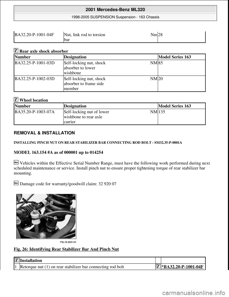
INSTALLING PINCH NUT ON REAR STABILIZER BAR CONNECTING ROD BOLT - SM32.35-P-0001A
MODEL 163.154 #A as of 000001 up to 014254
Vehicles within the Effective Serial Number Range, must have the following work performed during next
scheduled maintenance or service. Install pinch nut to ensure proper tightening torque of rear stabilizer bar
mounting.
Damage code for warranty/goodwill claim: 32 920 07
Fig. 26: Identifying Rear Stabilizer Bar And Pinch Nut
BA32.20-P-1001-04FNut, link rod to torsion
barNm28
NumberDesignationModel Series 163
BA32.25-P-1001-03DSelf-locking nut, shock
absorber to lower
wishboneNM85
BA32.25-P-1002-03DSelf-locking nut, shock
absorber to frame side
memberNM20
NumberDesignationModel Series 163
BA35.20-P-1003-07ASelf-locking nut of lower
wishbone to rear axle
carrierNM135
Installation
1Retorque nut (1) on rear stabilizer bar connecting rod bolt*BA32.20-P-1001-04F
2001 Mercedes-Benz ML320
1998-2005 SUSPENSION Suspension - 163 Chassis
me
Saturday, October 02, 2010 3:37:36 PMPage 27 © 2006 Mitchell Repair Information Company, LLC.
Page 3936 of 4133
Rear axle torsion bar
Parts ordering notes
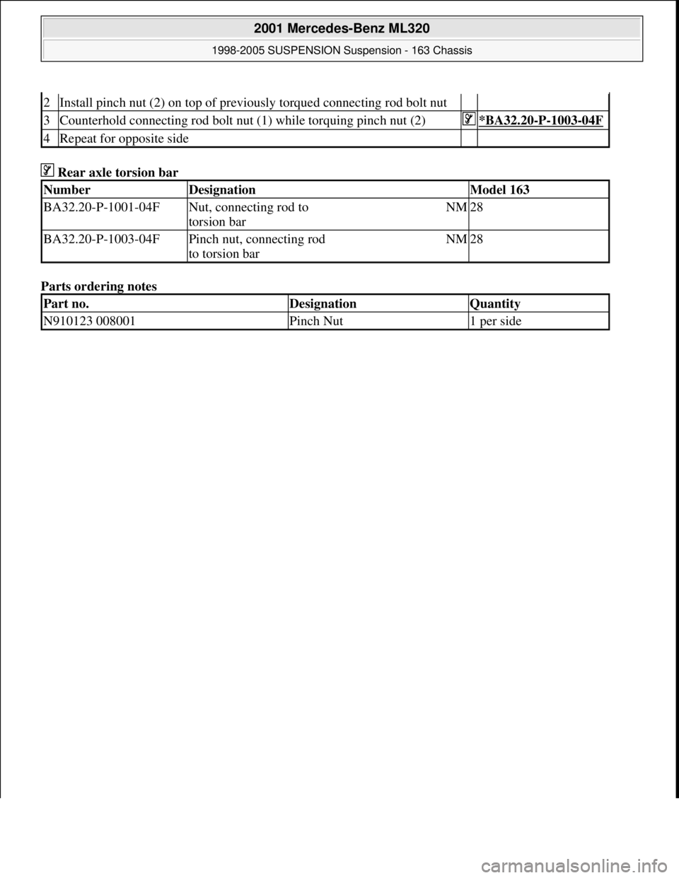
2Install pinch nut (2) on top of previously torqued connecting rod bolt nut
3Counterhold connecting rod bolt nut (1) while torquing pinch nut (2)*BA32.20-P-1003-04F
4Repeat for opposite side
NumberDesignationModel 163
BA32.20-P-1001-04FNut, connecting rod to
torsion barNM28
BA32.20-P-1003-04FPinch nut, connecting rod
to torsion barNM28
Part no.DesignationQuantity
N910123 008001Pinch Nut1 per side
2001 Mercedes-Benz ML320
1998-2005 SUSPENSION Suspension - 163 Chassis
me
Saturday, October 02, 2010 3:37:36 PMPage 28 © 2006 Mitchell Repair Information Company, LLC.
Page 3937 of 4133

GF77.20-P-3002GH
Synchronizing sliding /pop-up roof, function
19.2.97
MODEL
163 with CODE (414a) Electric glass sliding/pop-up roof
Synchronization
is necessary to match the counter status of the
position counter with the actual position of the sliding /pop-up roof in
the evaluation electronic module for the
sliding /pop-up roof (M12)
.
Synchronization is required when the
sliding /pop-up roof (M12)
has been disconnected from the power supply or a malfunction has
occurred during position measurement resulting in
desynchronization
.
In the desynchronized state the evaluation electronic module in the
sliding /pop-up roof (M12)
cannot recognize the position of the roof.
-----------------------------------------------------------------------------------------
In this case control is possible only to a limited extent; it is only
possible to open the pop-up roof for synchronization.
Synchronizing
When the
sliding /pop-up roof (M12)
is moved to the mechanical
end position "pop-up roof open" in the desynchronized state, the
evaluation electronic module recognizes that the motor is
locked up
and then performs
synchronization
; the position counter is set to "0"
and the sliding /pop-up roof can then be operated again without
limitations.
-----------------------------------------------------------------------------------------
Closing sliding /pop-up roof, function
GF77.20-P-2002GH
Desynchronizing sliding /pop-up roof, function
GF77.20-P-3003GH
Sliding/pop-up roof, location/purpose/
design/function
GF77.20-P-4100GH
Sliding /pop-up roof lock-up recognition,
function
GF77.20-P-3000GH
Sliding / pop-up roof position measurement,
function
GF77.20-P-3001GH
Copyright DaimlerChrysler AG 04.08.2006 CD-Ausgabe G/10/04 . This WIS print-out will not be recorde
d by Modification services.
Page 1
Page 3938 of 4133

BT27.51-P-0001-01A
Thickness of friction and steel disks K3
changed
TRANSMISSION
722.6
Production breakpoint data/changes/new features
Transmission/
Steering gear
Transmission ident.
end no. as of
Type of and reason for modification
722.6
Phased in
The thickness of the friction disks has been increased by 0.5 mm and
the thickness of the steel disks reduced by 0.7mm.
This improves heat dissipation and prevents shift judder
The clearance adjustment has not changed.
Copyright DaimlerChrysler AG 28.05.2006 CD-Ausgabe G/10/04 . This WIS print-out will not be recorde
d by Modification services.
Page 1
Page 3939 of 4133

BT27.51-P-0002-01A
Thickness of steel plates of B1, K1 and K2
modified
Transmission 722.6
k
TRANSMISSION
722.6## ## as of 1596205 as of 15.6.99
In order to reduce costs, the thickness of the steel plates has been
reduced by 0.7 mm.
The adjustment values for the play settings remain unchanged.
Copyright DaimlerChrysler AG 28.05.2006 CD-Ausgabe G/10/04 . This WIS print-out will not be recorde
d by Modification services.
Page 1
Page 3940 of 4133
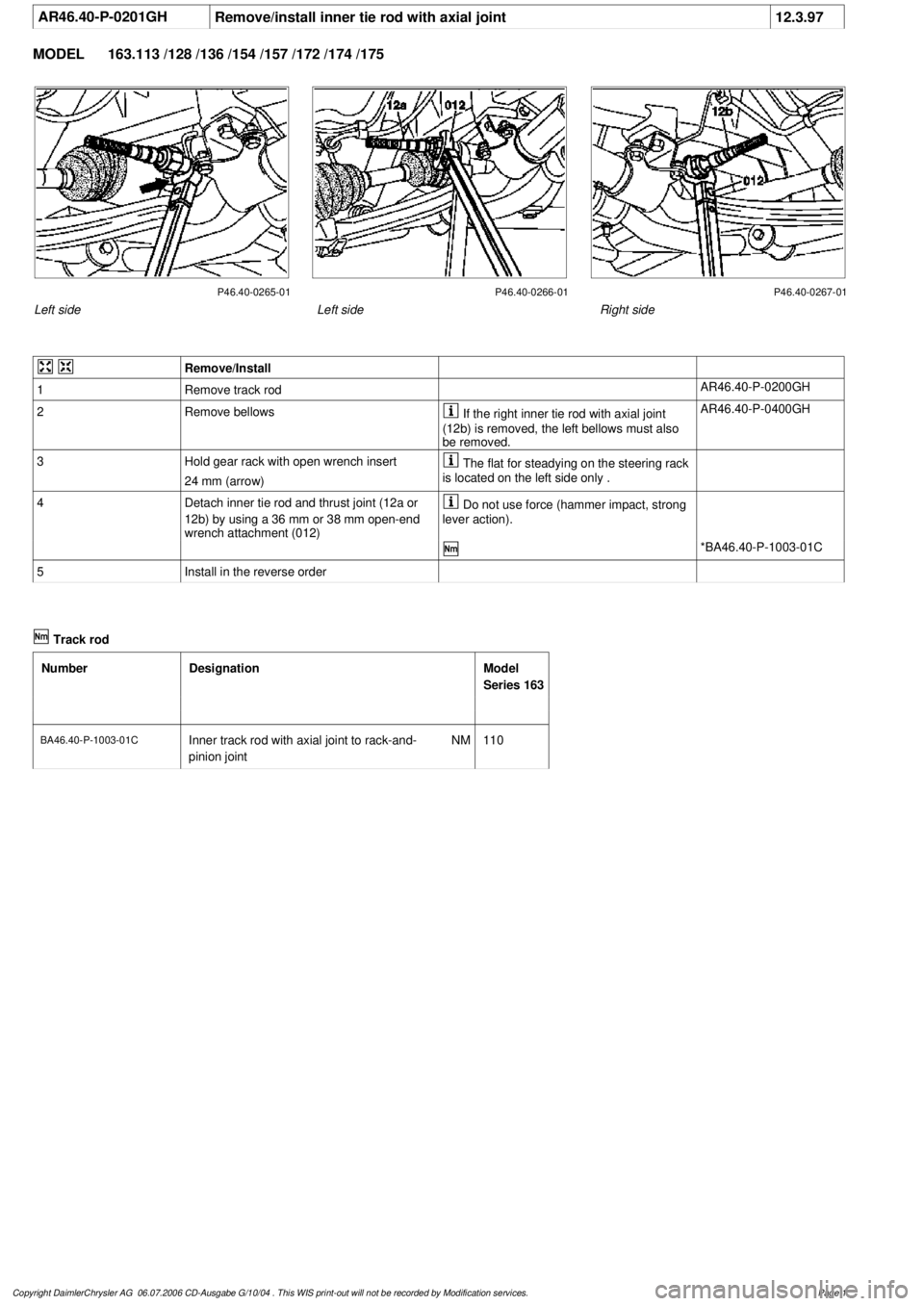
AR46.40-P-0201GH
Remove/install inner tie rod with axial joint
12.3.97
MODEL
163.113 /128 /136 /154 /157 /172 /174 /175
P46.40-0265-01 P46.40-0266-01 P46.40-0267-01
Left side
Right side
Left side
Remove/Install
1
Remove track rod
AR46.40-P-0200GH
2
Remove bellows
If the right inner tie rod with axial joint
(12b) is removed, the left bellows must also
be removed.
AR46.40-P-0400GH
3
Hold gear rack with open wrench insert
24 mm (arrow)
The flat for steadying on the steering rack
is located on the left side only .
4
Detach inner tie rod and thrust joint (12a or
12b) by using a 36 mm or 38 mm open-end
wrench attachment (012)
Do not use force (hammer impact, strong
lever action).
*BA46.40-P-1003-01C
5
Install in the reverse order
Track rod
Number
Designation
Model
Series 163
BA46.40-P-1003-01C
Inner track rod with axial joint to rack-and-
pinion joint
NM
110
Copyright DaimlerChrysler AG 06.07.2006 CD-Ausgabe G/10/04 . This WIS print-out will not be recorde
d by Modification services.
Page 1