MERCEDES-BENZ ML350 1997 Complete Repair Manual
Manufacturer: MERCEDES-BENZ, Model Year: 1997, Model line: ML350, Model: MERCEDES-BENZ ML350 1997Pages: 4133, PDF Size: 88.89 MB
Page 3901 of 4133
GF54.30-P-3009A
Stepper motor, location/design/function
7.7.99
MODEL
129, 140 as of 1.6.96,
163, 168, 170,
202 as of 1.8.96,
208,
210 as of 1.6.96,
215, 220
P54.30-0521-06
General
Stepper motors are motors which, like most
electric motors, consist of a fixed stator and a
moveable rotor. The rotary motion is not
continuous, rather the rotor turns in steps, a
certain angle at a time, for example 90°.
Design
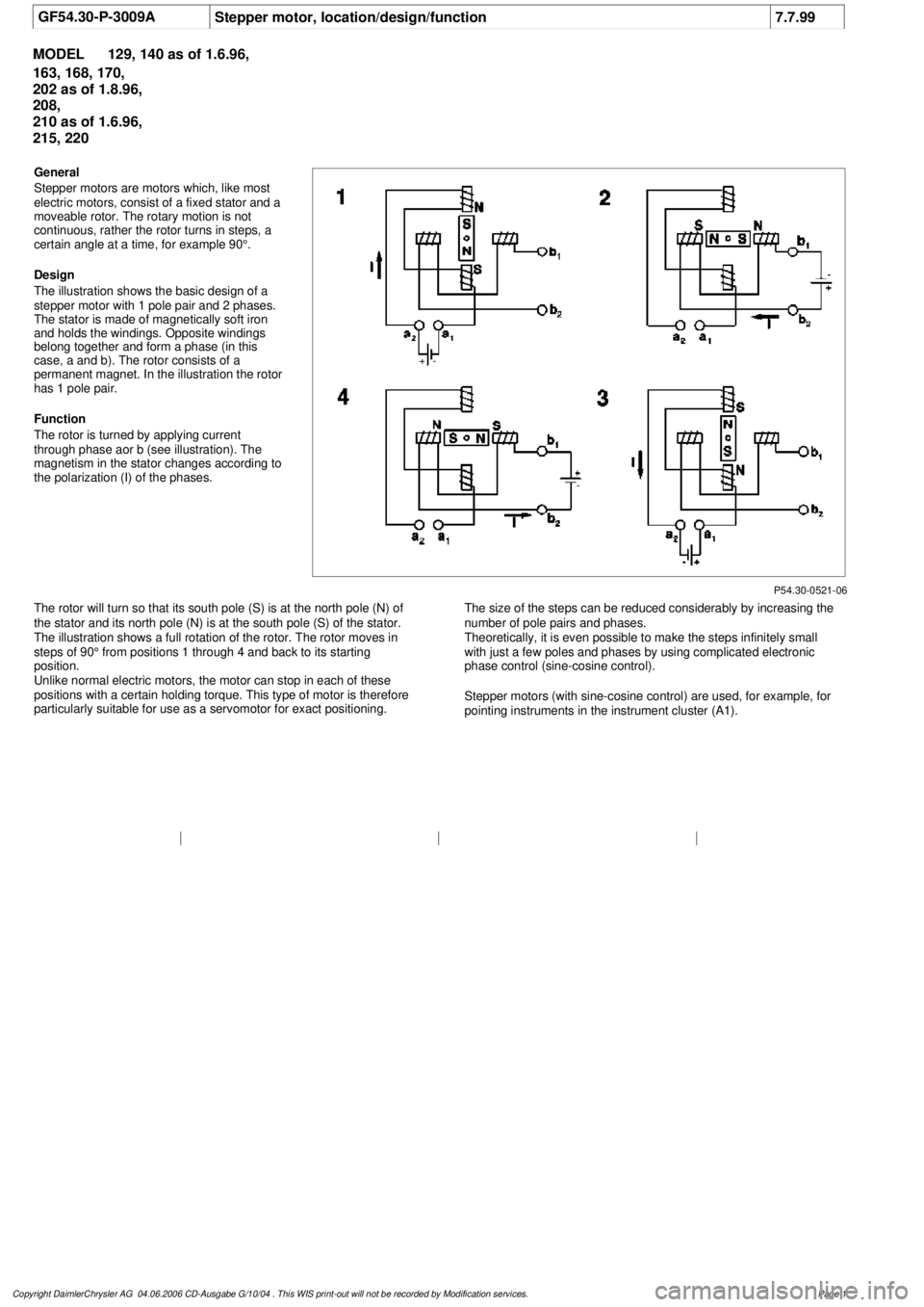
The illustration shows the basic design of a
stepper motor with 1 pole pair and 2 phases.
The stator is made of magnetically soft iron
and holds the windings. Opposite windings
belong together and form a phase (in this
case, a and b). The rotor consists of a
permanent magnet. In the illustration the rotor
has 1 pole pair.
Function
The rotor is turned by applying current
through phase aor b (see illustration). The
magnetism in the stator changes according to
the polarization (I) of the phases.
The rotor will turn so that its south pole (S) is at the north pole (N) of
the stator and its north pole (N) is at the south pole (S) of the stator.
The illustration shows a full rotation of the rotor. The rotor moves in
steps of 90° from positions 1 through 4 and back to its starting
position.
Unlike normal electric motors, the motor can stop in each of these
positions with a certain holding torque. This type of motor is therefore
particularly suitable for use as a servomotor for exact positioning.
The size of the steps can be reduced considerably by increasing the
number of pole pairs and phases.
Theoretically, it is even possible to make the steps infinitely small
with just a few poles and phases by using complicated electronic
phase control (sine-cosine control).
Stepper motors (with sine-cosine control) are used, for example, for
pointing instruments in the instrument cluster (A1).
Copyright DaimlerChrysler AG 04.06.2006 CD-Ausgabe G/10/04 . This WIS print-out will not be recorde
d by Modification services.
Page 1
Page 3902 of 4133
BT27.35-P-0004-01A
Strainer for modulating pressure and shift
pressure control solenoid valve, new
Transmission 722.6
k
TRANSMISSION
722.6## ## as of 0538312
P27.35-0248-06
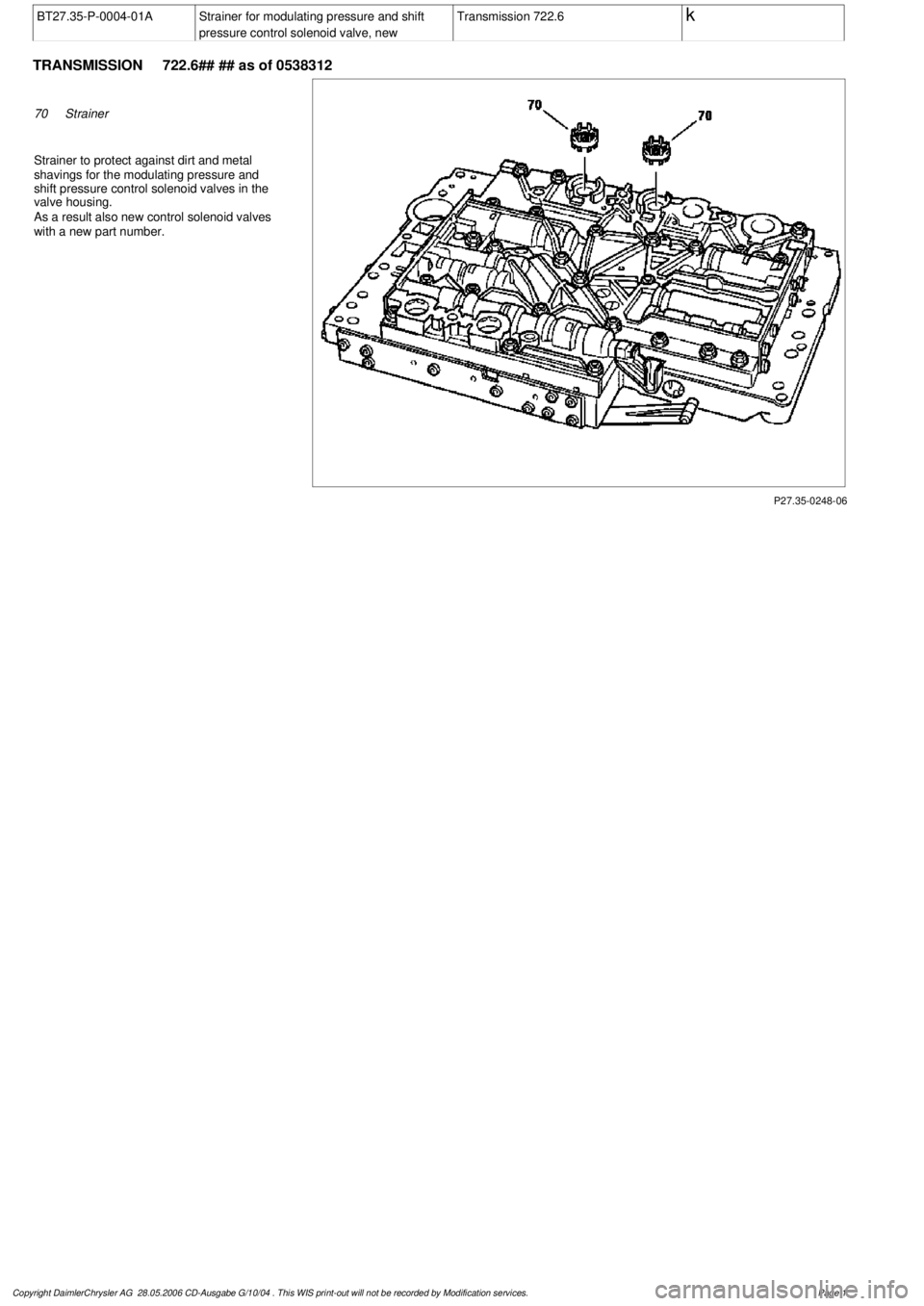
70
Strainer
Strainer to protect against dirt and metal
shavings for the modulating pressure and
shift pressure control solenoid valves in the
valve housing.
As a result also new control solenoid valves
with a new part number.
Copyright DaimlerChrysler AG 28.05.2006 CD-Ausgabe G/10/04 . This WIS print-out will not be recorde
d by Modification services.
Page 1
Page 3903 of 4133
BT27.35-P-0005-01A
Strainer in inlet to converter lock-up control
solenoid valve, new
Transmission 722.6
k
TRANSMISSION
722.6## ## as of 0485895
P27.35-0251-09
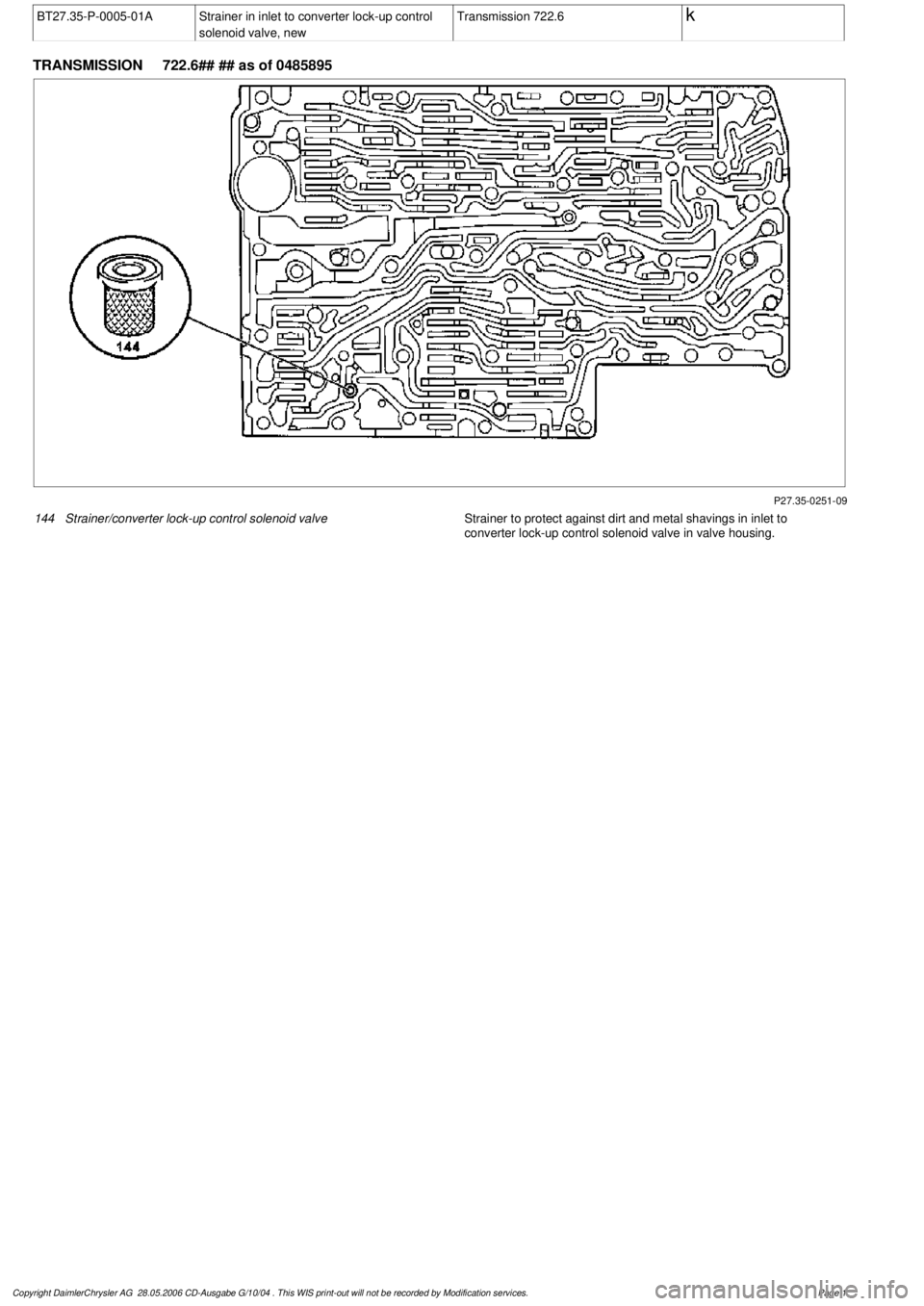
144
Strainer/converter lock-up control solenoid valve
Strainer to protect against dirt and metal shavings in inlet to
converter lock-up control solenoid valve in valve housing.
Copyright DaimlerChrysler AG 28.05.2006 CD-Ausgabe G/10/04 . This WIS print-out will not be recorde
d by Modification services.
Page 1
Page 3904 of 4133
AR88.30-P-0200-04GH
Prepare cutting tool
Commercially available tools
(see Workshop Equipment Manual)
Number
Designation
Make (e. g.)
Order number
WH58.30-Z-1010-10A
Cutting tool kit (compressed-air tool + blades)
Europe:
The Barn
Holly Tree Farm
Holmes Chapel Road
Lower Withington,
Cheshire, SK11 9DT
England
Tel.:
+44 1477 571700
Japan:
Osaka Chamber of
Commerce
2-8 Hommachibashi
Chuo-ku
Osaka, Japan, 540-
0029
Tel.:+81 6 6944 6445
USA:
SPX
Dealer Equipment
Services Tel.:
+1-888-458-4040
P88.30-2070-01
Observe general notes, guidelines and safety precautions for operation of pneumatic tools
contained in the operating instructions, included with the tool kit to avoid hazards and incorrect
operation.
Sharpen blades before use and while cutting with wet whetstone WK8 to obtain best results.
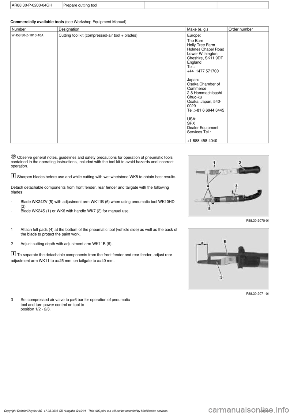
Detach detachable components from front fender, rear fender and tailgate with the following
blades:
-
Blade WK24ZV (5) with adjustment arm WK11B (6) when using pneumatic tool WK10HD
(3).
-
Blade WK24S (1) or WK6 with handle WK7 (2) for manual use.
P88.30-2071-01
1
Attach felt pads (4) at the bottom of the pneumatic tool (vehicle side) as well as the back of
the blade to protect the paint work.
2
Adjust cutting depth with adjustment arm WK11B (6).
To separate the detachable components from the front fender and rear fender, adjust rear
adjustment arm WK11 to a=25 mm, on tailgate to a=40 mm.
3
Set compressed air valve to p=6 bar for operation of pneumatic
tool and turn power control on tool to
position 1/2 - 2/3.
Copyright DaimlerChrysler AG 17.05.2006 CD-Ausgabe G/10/04 . This WIS print-out will not be recorde
d by Modification services.
Page 1
Page 3905 of 4133
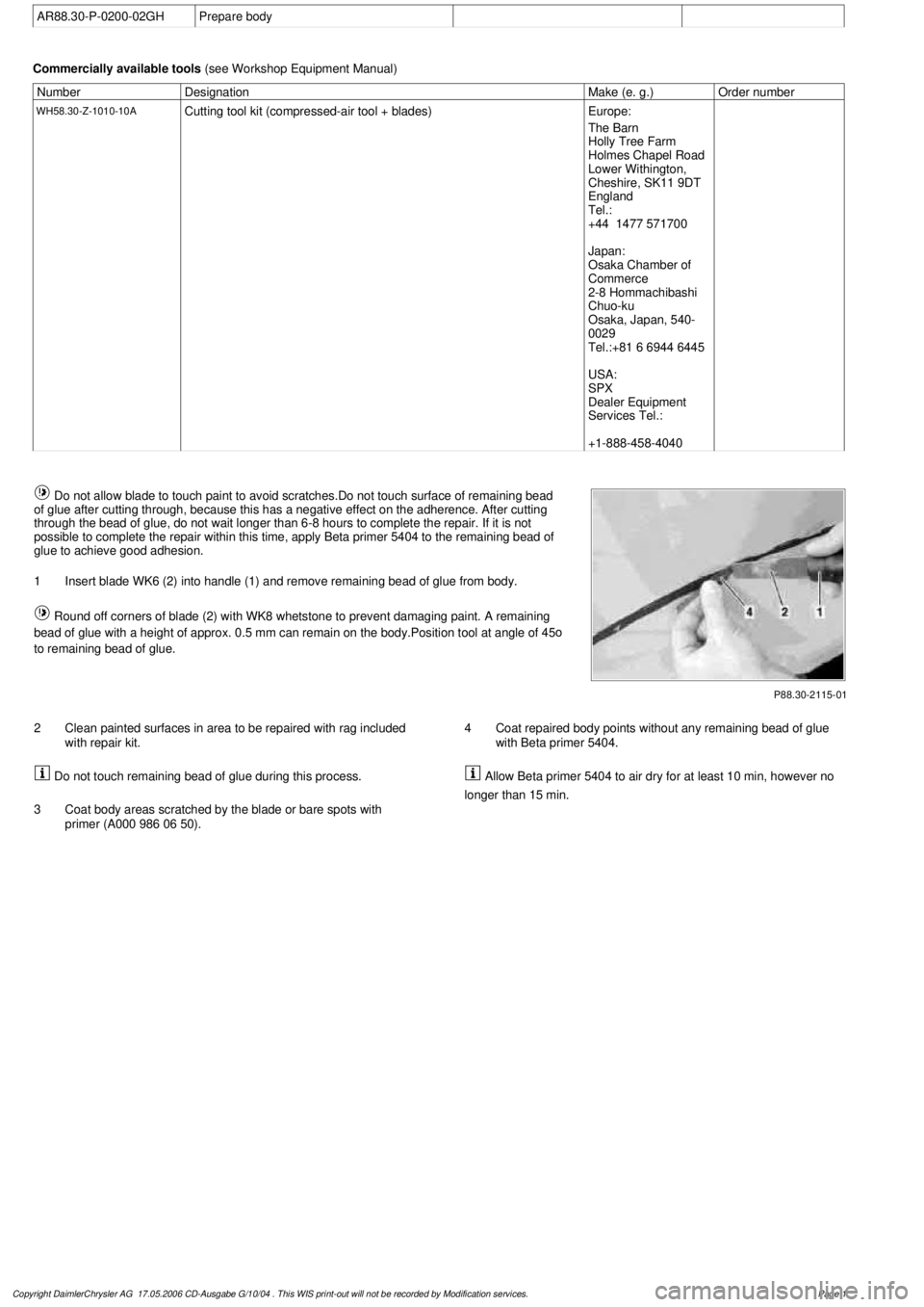
AR88.30-P-0200-02GH
Prepare body
Commercially available tools
(see Workshop Equipment Manual)
Number
Designation
Make (e. g.)
Order number
WH58.30-Z-1010-10A
Cutting tool kit (compressed-air tool + blades)
Europe:
The Barn
Holly Tree Farm
Holmes Chapel Road
Lower Withington,
Cheshire, SK11 9DT
England
Tel.:
+44 1477 571700
Japan:
Osaka Chamber of
Commerce
2-8 Hommachibashi
Chuo-ku
Osaka, Japan, 540-
0029
Tel.:+81 6 6944 6445
USA:
SPX
Dealer Equipment
Services Tel.:
+1-888-458-4040
P88.30-2115-01
Do not allow blade to touch paint to avoid scratches.Do not touch surface of remaining bead
of glue after cutting through, because this has a negative effect on the adherence. After cutting
through the bead of glue, do not wait longer than 6-8 hours to complete the repair. If it is not
possible to complete the repair within this time, apply Beta primer 5404 to the remaining bead of
glue to achieve good adhesion.
1
Insert blade WK6 (2) into handle (1) and remove remaining bead of glue from body.
Round off corners of blade (2) with WK8 whetstone to prevent damaging paint. A remaining
bead of glue with a height of approx. 0.5 mm can remain on the body.Position tool at angle of 45
o
to remaining bead of glue.
2
Clean painted surfaces in area to be repaired with rag included
with repair kit.
Do not touch remaining bead of glue during this process.
3
Coat body areas scratched by the blade or bare spots with
primer (A000 986 06 50).
4
Coat repaired body points without any remaining bead of glue
with Beta primer 5404. Allow Beta primer 5404 to air dry for at least 10 min, however no
longer than 15 min.
Copyright DaimlerChrysler AG 17.05.2006 CD-Ausgabe G/10/04 . This WIS print-out will not be recorde
d by Modification services.
Page 1
Page 3906 of 4133
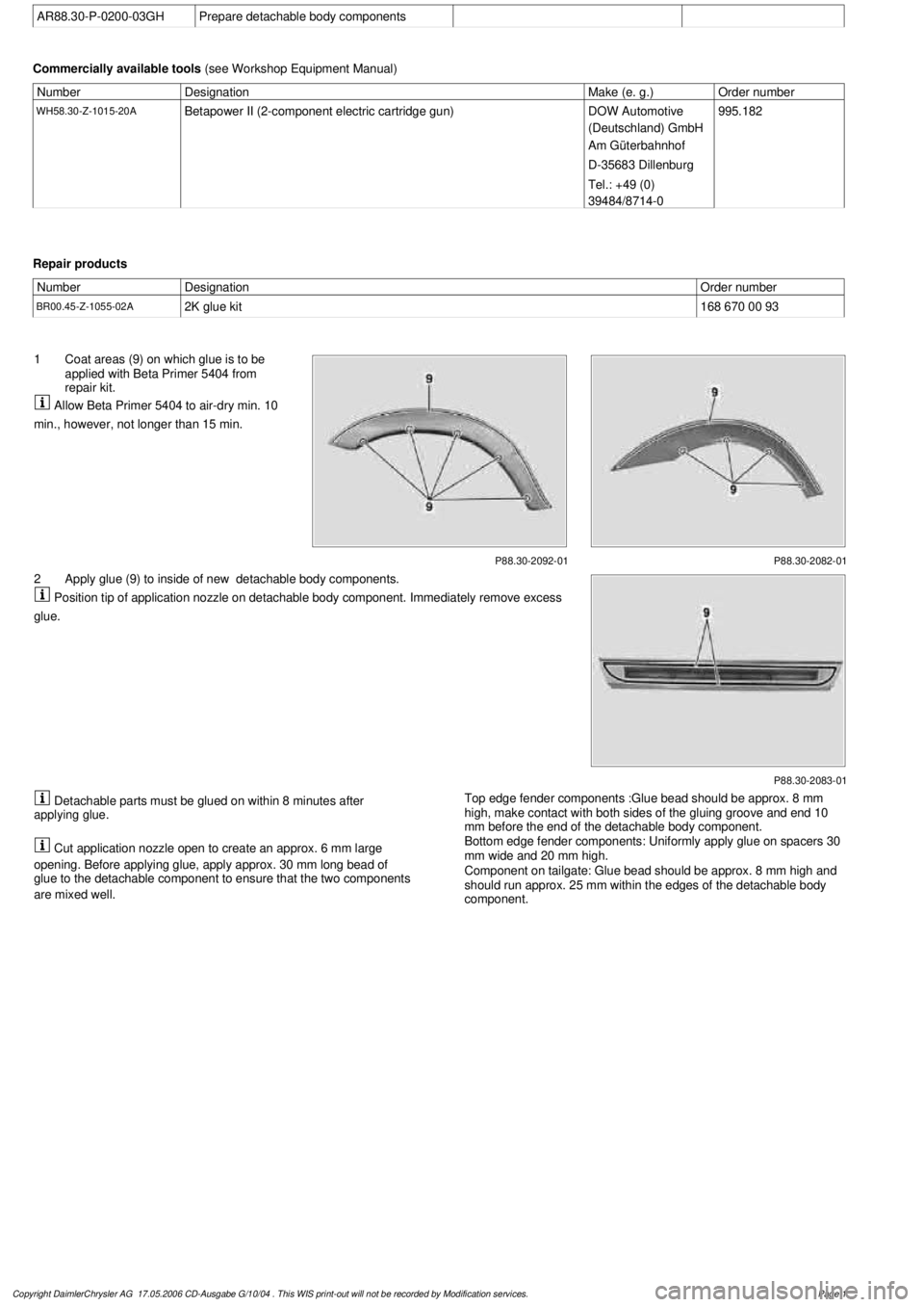
AR88.30-P-0200-03GH
Prepare detachable body components
Commercially available tools
(see Workshop Equipment Manual)
Number
Designation
Make (e. g.)
Order number
WH58.30-Z-1015-20A
Betapower II (2-component electric cartridge gun)
DOW Automotive
(Deutschland) GmbH
Am Güterbahnhof
D-35683 Dillenburg
Tel.: +49 (0)
39484/8714-0
995.182
Repair products
Number
Designation
Order number
BR00.45-Z-1055-02A
2K glue kit
168 670 00 93
P88.30-2092-01
1
Coat areas (9) on which glue is to be
applied with Beta Primer 5404 from
repair kit.
Allow Beta Primer 5404 to air-dry min. 10
min., however, not longer than 15 min.
P88.30-2082-01
P88.30-2083-01
2
Apply glue (9) to inside of new
detachable body components.
Position tip of application nozzle on detachable body component. Immediately remove excess
glue.
Detachable parts must be glued on within 8 minutes after
applying glue.
Cut application nozzle open to create an approx. 6 mm large
opening. Before applying glue, apply approx. 30 mm long bead of
glue to the detachable component to ensure that the two components
are mixed well.
Top edge fender components :Glue bead should be approx. 8 mm
high, make contact with both sides of the gluing groove and end 10
mm before the end of the detachable body component.
Bottom edge fender components: Uniformly apply glue on spacers 30
mm wide and 20 mm high.
Component on tailgate: Glue bead should be approx. 8 mm high and
should run approx. 25 mm within the edges of the detachable body
component.
Copyright DaimlerChrysler AG 17.05.2006 CD-Ausgabe G/10/04 . This WIS print-out will not be recorde
d by Modification services.
Page 1
Page 3907 of 4133
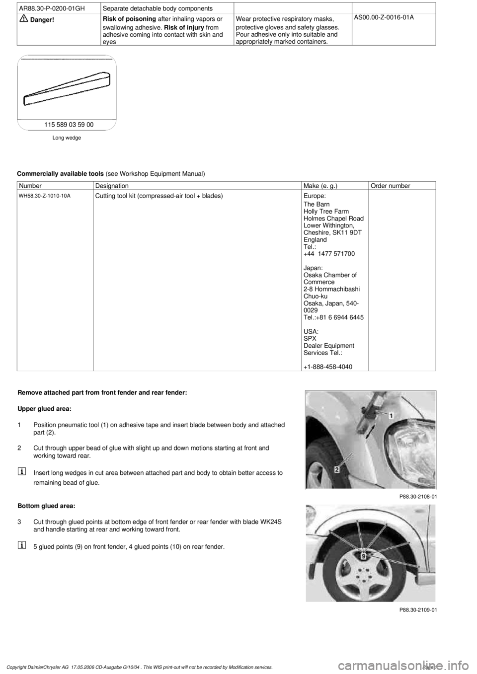
AR88.30-P-0200-01GH
Separate detachable body components
Danger!
Risk of poisoning
after inhaling vapors or
swallowing adhesive.
Risk of injury
from
adhesive coming into contact with skin and
eyes
Wear protective respiratory masks,
protective gloves and safety glasses.
Pour adhesive only into suitable and
appropriately marked containers.
AS00.00-Z-0016-01A
Long wedge
115 589 03 59 00
Commercially available tools
(see Workshop Equipment Manual)
Number
Designation
Make (e. g.)
Order number
WH58.30-Z-1010-10A
Cutting tool kit (compressed-air tool + blades)
Europe:
The Barn
Holly Tree Farm
Holmes Chapel Road
Lower Withington,
Cheshire, SK11 9DT
England
Tel.:
+44 1477 571700
Japan:
Osaka Chamber of
Commerce
2-8 Hommachibashi
Chuo-ku
Osaka, Japan, 540-
0029
Tel.:+81 6 6944 6445
USA:
SPX
Dealer Equipment
Services Tel.:
+1-888-458-4040
P88.30-2108-01
Remove attached part from front fender and rear fender:
Upper glued area:
1
Position pneumatic tool (1) on adhesive tape and insert blade between body and attached
part (2).
2
Cut through upper bead of glue with slight up and down motions starting at front and
working toward rear.
Insert long wedges in cut area between attached part and body to obtain better access to
remaining bead of glue.
P88.30-2109-01
Bottom glued area:
3
Cut through glued points at bottom edge of front fender or rear fender with blade WK24S
and handle starting at rear and working toward front.
5 glued points (9) on front fender, 4 glued points (10) on rear fender.
Copyright DaimlerChrysler AG 17.05.2006 CD-Ausgabe G/10/04 . This WIS print-out will not be recorde
d by Modification services.
Page 1
Page 3908 of 4133
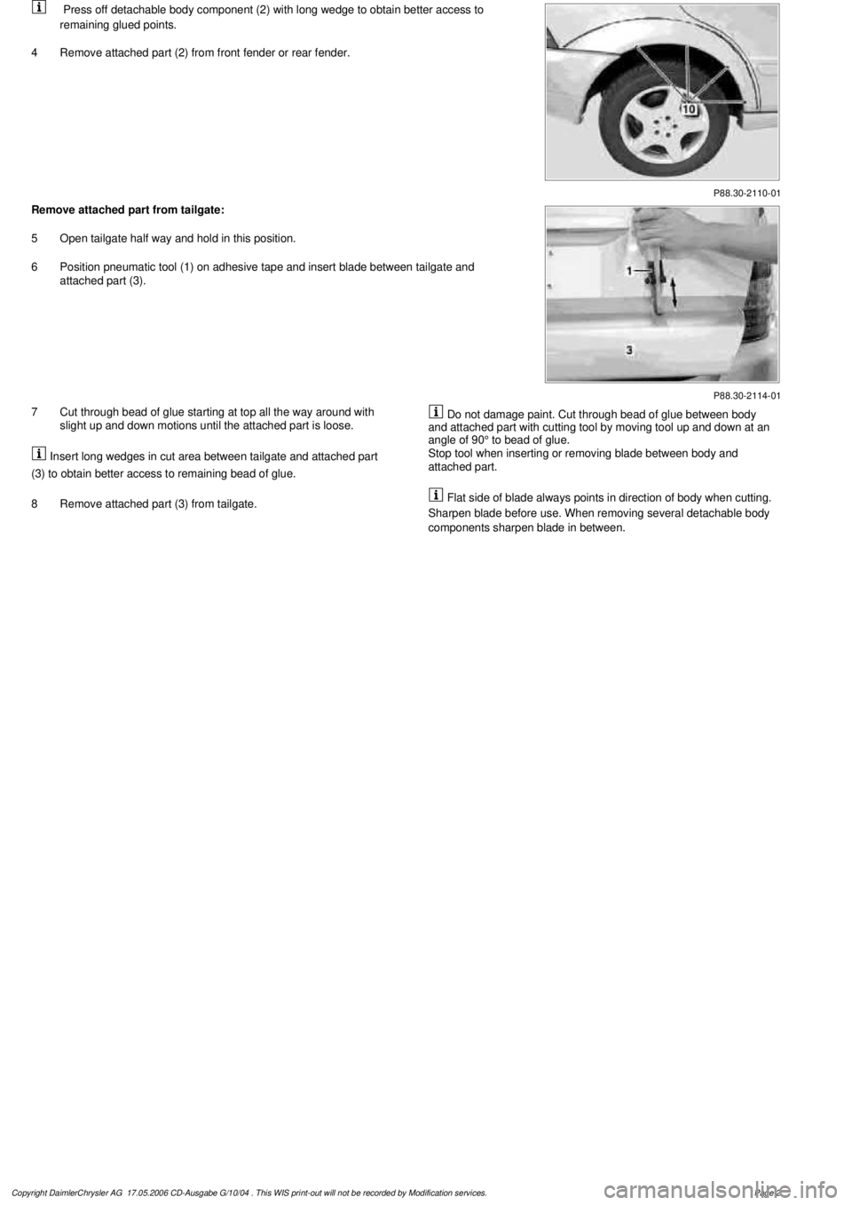
P88.30-2110-01
Press off detachable body component (2) with long wedge to obtain better access to
remaining glued points.
4
Remove attached part (2) from front fender or rear fender.
P88.30-2114-01
Remove attached part from tailgate:
5
Open tailgate half way and hold in this position.
6
Position pneumatic tool (1) on adhesive tape and insert blade between tailgate and
attached part (3).
7
Cut through bead of glue starting at top all the way around with
slight up and down motions until the attached part is loose.
Insert long wedges in cut area between tailgate and attached part
(3) to obtain better access to remaining bead of glue.
8
Remove attached part (3) from tailgate.
Do not damage paint. Cut through bead of glue between body
and attached part with cutting tool by moving tool up and down at an
angle of 90° to bead of glue.
Stop tool when inserting or removing blade between body and
attached part.
Flat side of blade always points in direction of body when cutting.
Sharpen blade before use. When removing several detachable body
components sharpen blade in between.
Copyright DaimlerChrysler AG 17.05.2006 CD-Ausgabe G/10/04 . This WIS print-out will not be recorde
d by Modification services.
Page 2
Page 3909 of 4133
1998-2005 SUSPENSION
Suspension - 163 Chassis
GENERAL INFORMATION
GENERAL NOTES ON WORKING ON VEHICLES WITH LEVEL CONTROL/ADS - AH32.00-P-0002-01A
All models with code 216b, 216c, 217a, 480
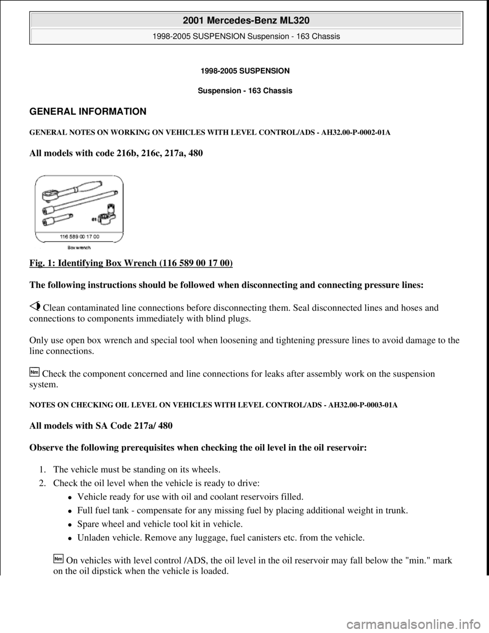
Fig. 1: Identifying Box Wrench (116 589 00 17 00)
The following instructions should be followed when disconnecting and connecting pressure lines:
Clean contaminated line connections before disconnecting them. Seal disconnected lines and hoses and
connections to components immediately with blind plugs.
Only use open box wrench and special tool when loosening and tightening pressure lines to avoid damage to the
line connections.
Check the component concerned and line connections for leaks after assembly work on the suspension
system.
NOTES ON CHECKING OIL LEVEL ON VEHICLES WITH LEVEL CONTROL/ADS - AH32.00-P-0003-01A
All models with SA Code 217a/ 480
Observe the following prerequisites when checking the oil level in the oil reservoir:
1. The vehicle must be standing on its wheels.
2. Check the oil level when the vehicle is ready to drive:
Vehicle ready for use with oil and coolant reservoirs filled.
Full fuel tank - compensate for any missing fuel by placing additional weight in trunk.
Spare wheel and vehicle tool kit in vehicle.
Unladen vehicle. Remove any luggage, fuel canisters etc. from the vehicle.
On vehicles with level control /ADS, the oil level in the oil reservoir may fall below the "min." mark
on the oil dipstick when the vehicle is loaded.
2001 Mercedes-Benz ML320
1998-2005 SUSPENSION Suspension - 163 Chassis
2001 Mercedes-Benz ML320
1998-2005 SUSPENSION Suspension - 163 Chassis
me
Saturday, October 02, 2010 3:37:35 PMPage 1 © 2006 Mitchell Repair Information Company, LLC.
me
Saturday, October 02, 2010 3:37:38 PMPage 1 © 2006 Mitchell Repair Information Company, LLC.
Page 3910 of 4133
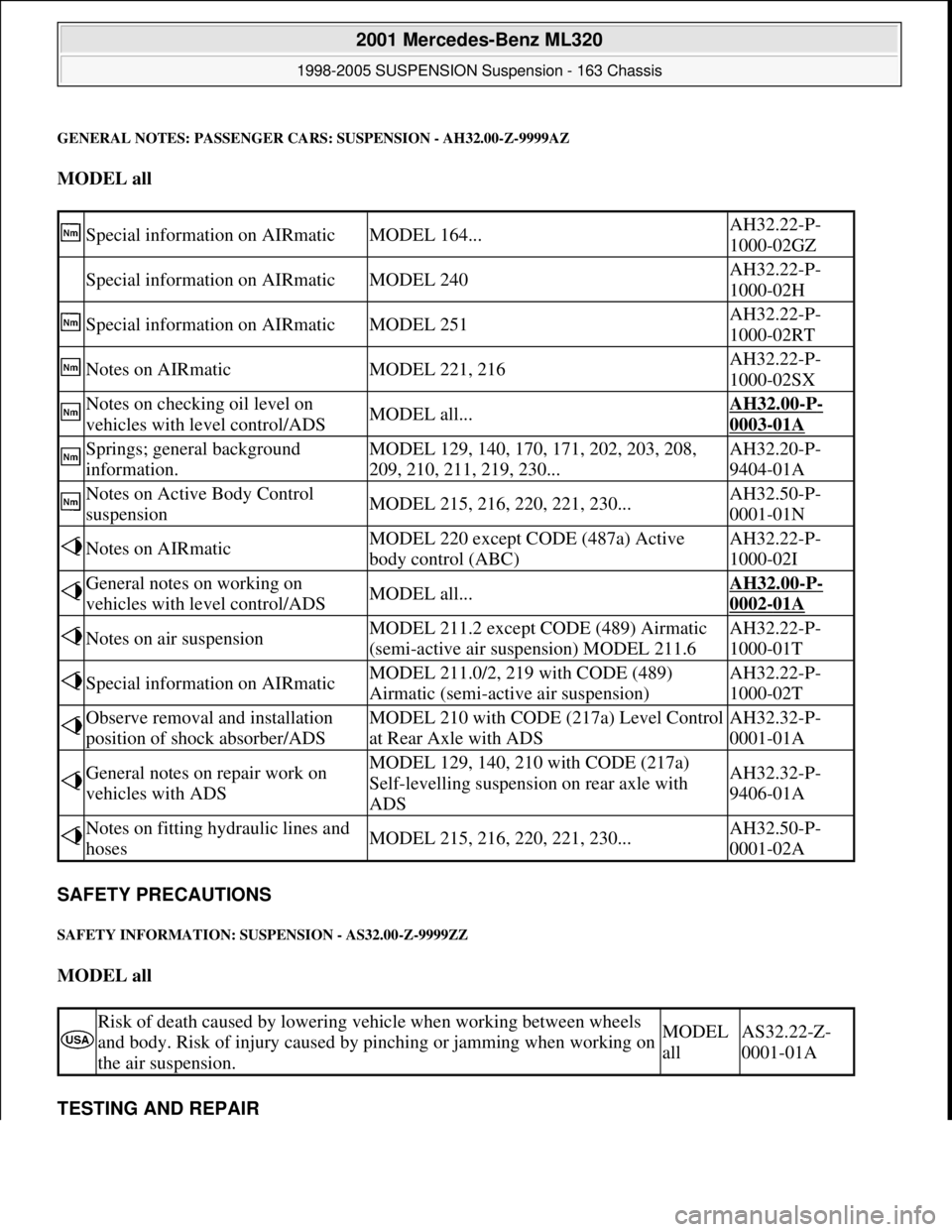
GENERAL NOTES: PASSENGER CARS: SUSPENSION - AH32.00-Z-9999AZ
MODEL all
SAFETY PRECAUTIONS
SAFETY INFORMATION: SUSPENSION - AS32.00-Z-9999ZZ
MODEL all
TESTING AND REPAIR
Special information on AIRmaticMODEL 164...AH32.22-P-
1000-02GZ
Special information on AIRmaticMODEL 240AH32.22-P-
1000-02H
Special information on AIRmaticMODEL 251AH32.22-P-
1000-02RT
Notes on AIRmaticMODEL 221, 216AH32.22-P-
1000-02SX
Notes on checking oil level on
vehicles with level control/ADSMODEL all...AH32.00-P-
0003-01A
Springs; general background
information.MODEL 129, 140, 170, 171, 202, 203, 208,
209, 210, 211, 219, 230...AH32.20-P-
9404-01A
Notes on Active Body Control
suspensionMODEL 215, 216, 220, 221, 230...AH32.50-P-
0001-01N
Notes on AIRmaticMODEL 220 except CODE (487a) Active
body control (ABC)AH32.22-P-
1000-02I
General notes on working on
vehicles with level control/ADSMODEL all...AH32.00-P-
0002-01A
Notes on air suspensionMODEL 211.2 except CODE (489) Airmatic
(semi-active air suspension) MODEL 211.6AH32.22-P-
1000-01T
Special information on AIRmaticMODEL 211.0/2, 219 with CODE (489)
Airmatic (semi-active air suspension)AH32.22-P-
1000-02T
Observe removal and installation
position of shock absorber/ADSMODEL 210 with CODE (217a) Level Control
at Rear Axle with ADSAH32.32-P-
0001-01A
General notes on repair work on
vehicles with ADSMODEL 129, 140, 210 with CODE (217a)
Self-levelling suspension on rear axle with
ADSAH32.32-P-
9406-01A
Notes on fitting hydraulic lines and
hosesMODEL 215, 216, 220, 221, 230...AH32.50-P-
0001-02A
Risk of death caused by lowering vehicle when working between wheels
and body. Risk of injury caused by pinching or jamming when working on
the air suspension.MODEL
allAS32.22-Z-
0001-01A
2001 Mercedes-Benz ML320
1998-2005 SUSPENSION Suspension - 163 Chassis
me
Saturday, October 02, 2010 3:37:35 PMPage 2 © 2006 Mitchell Repair Information Company, LLC.