phone MERCEDES-BENZ ML350 1997 Complete Workshop Manual
[x] Cancel search | Manufacturer: MERCEDES-BENZ, Model Year: 1997, Model line: ML350, Model: MERCEDES-BENZ ML350 1997Pages: 4133, PDF Size: 88.89 MB
Page 1504 of 4133
Model 129 HU - telephone (or Tele Aid) - CDC - HU
Model 163 HU - Sound - CDC - telephone (or TELE AID) - HU
Model 168 HU - telephone - CDC - HU
Model 170 HU - telephone - HU (ECE); HU - CDC - HU (Japan)
Model 202/208 HU - CDC - telephone (or Tele Aid) - VCS - HU
Model 203/209 HU - sound - portable CTEL interface - VCS - CDC - HU
Model 210 HU - CDC - VCS - telephone (or TELE AID) - HU
Model 215/220 HU - sound - CDC - telephone (or Tele Aid) - VCS - optional portable CTEL interface - HU
Model 230 HU - Sound - CDC - Telephone (or TELE AID) - SBS - HU
Model 414/463 HU - CDC - telephone - HU
The sequence represents the current maximum equipment. If special equipment (SA) is omitted, the
respective item is deleted, resulting in a new ring sequence.
Read out actual configuration using STAR DIAGNOSIS
As of September 1999 it is possible to read out the current actual configuration of a functioning D2B ring by
means of STAR DIAGNOSIS. This is particularly important in the case of later expansion of the D2B ring and
when retrofitting D2B components e.g. telephone.
In the diagnosis system there is the menu item "Retrofitting D2B components". Under this menu item, the
current actual configuration of a vehicle can be read out and written back immediately as a new nominal
configuration. The process is self-explanatory.
BASIC KNOWLEDGE
DIGITAL DATA BUS (D2B), FUNCTION - GF82.00-P-0001A
MODEL 129 as of 1.6.98, 163, 168 as of 1.9.98, 170, 202 as of 1.6.98, 203, 208, 210 as of 1.6.98, 215, 220
Component sequence, exemplified on model 220 with code (819) 6-disc CD changer, with code (810)
sound system, with code (813) voice control system (VCS) and with code (855) TELE AID
2001 Mercedes-Benz ML320
1998-2005 ACCESSORIES & BODY, CAB Electrical System - Body - 163 Chassis
me
Saturday, October 02, 2010 3:30:04 PMPage 9 © 2006 Mitchell Repair Information Company, LLC.
Page 1506 of 4133
Short-circuit resistance
Zero potential connection of components
No oxidation
Low weight of fiber optical cable
Minimum diameter of wiring harness
The digital data bus (D2B) has a closed ring structure. The communication and data components are arranged
here in a distributor line (in-series circuit). This arrangement is type specific and is illustrated by way of an
example on model 220 as follows:
Radio (A2)
CD player with changer (in trunk) (A2/6), with code (819) 6-disc CD changer
Sound amplifier (A2/13), with code (810) Sound System
Voice control system control unit (A35/11), with code (813) voice control system (VCS)
Telephone and TELE AID transmitter/receiver, D2B (A35/17), with code (855) TELE AID
Data transfer is conducted here in one direction only, i.e. the optical pulses for the voice control system control
unit (A35/11), for vehicles with code (813) voice control system (VCS), on model 220 pass through all
components connected to the ring, before arriving at the target components.
When the system is first put into operation, a system test is performed. In doing so the individual components
and their sequence in the ring structure of the Digital Data Bus (D2B) are registered by the component with the
master function.
A type-specific sequence is stored ex-factory. In turn, the storing of a sequence ex-factory means: if the radio
(A2) is taken from one model series and installed into another one, then during a system test the different
sequence of the components and an error message are filed in the diagnostic trouble code memory.
An error message is also filed if the radio (A2) is exchanged within a model series with different equipment
components. The system goes to the operational state regardless of the error message. STAR DIAGNOSIS
enables the sequence of the components to be subsequently altered in the Digital Data Bus (D2B).
The Digital Data Bus (D2B) is diagnosis capable via the data link connector (X11/4), except for models 129
and 202.
The operating principle of the Digital Data Bus (D2B) is the same for all model series; all that changes is the
sequence of components depending on the national version and equipment specification.
TABLE OF CONTENTS, FUNCTION DESCRIPTION OF DIGITAL DATA BUS (D2B) - GF82.00-P-0999ZZ
MODEL 129 as of 1.6.98, 163, 168 as of 1.9.98, 170, 202 as of 1.6.98, 203, 208, 210 as of 1.6.98, 215, 220
Data transfer, function GF82.00-P-2000A
2001 Mercedes-Benz ML320
1998-2005 ACCESSORIES & BODY, CAB Electrical System - Body - 163 Chassis
me
Saturday, October 02, 2010 3:30:04 PMPage 11 © 2006 Mitchell Repair Information Company, LLC.
Page 1510 of 4133
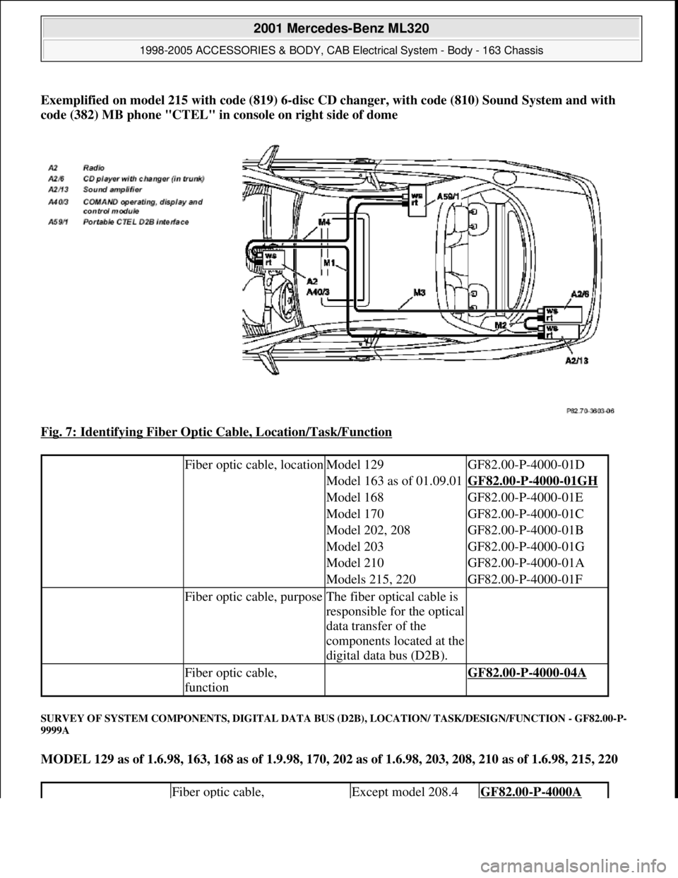
Exemplified on model 215 with code (819) 6-disc CD changer, with code (810) Sound System and with
code (382) MB phone "CTEL" in console on right side of dome
Fig. 7: Identifying Fiber Optic Cable, Location/Task/Function
SURVEY OF SYSTEM COMPONENTS, DIGITAL DATA BUS (D2B), LOCATION/ TASK/DESIGN/FUNCTION - GF82.00-P-
9999A
MODEL 129 as of 1.6.98, 163, 168 as of 1.9.98, 170, 202 as of 1.6.98, 203, 208, 210 as of 1.6.98, 215, 220
Fiber optic cable, locationModel 129GF82.00-P-4000-01D
Model 163 as of 01.09.01GF82.00-P-4000-01GH
Model 168GF82.00-P-4000-01E
Model 170GF82.00-P-4000-01C
Model 202, 208GF82.00-P-4000-01B
Model 203GF82.00-P-4000-01G
Model 210GF82.00-P-4000-01A
Models 215, 220GF82.00-P-4000-01F
Fiber optic cable, purposeThe fiber optical cable is
responsible for the optical
data transfer of the
components located at the
digital data bus (D2B).
Fiber optic cable,
function GF82.00-P-4000-04A
Fiber optic cable, Except model 208.4GF82.00-P-4000A
2001 Mercedes-Benz ML320
1998-2005 ACCESSORIES & BODY, CAB Electrical System - Body - 163 Chassis
me
Saturday, October 02, 2010 3:30:04 PMPage 15 © 2006 Mitchell Repair Information Company, LLC.
Page 1558 of 4133
and for reading and loading navigation data from navigation data CDs.
A special navigation CD must be inserted for navigation purposes.
The CD player integrated into the radio and navigation unit (A2/56) provides the following audio functions:
Fast forward or reverse (music search) The music played is audible during fast forward or reverse.
"Scan" function
Each track on a CD is played for 8 s. After a complete run through, the scan function is automatically
terminated.
"Random" function
All the tracks on a CD are played according to a random selection.
"Repeat" function
The current track is repeated.
"Display" function
The number and elapsed playing time for the current track, the total playing time and the number of tracks
on the CD are displayed.
Each CD includes a permanently stored table of contents (TOC record). The table of contents (TOC entry)
contains information such as the number of tracks on a CD and the CD's total playing time.
CD playback is automatically interrupted by the following functions (pause function):
Traffic messages and public warning messages over the radio data system (RDS)
Incoming telephone calls
CD playback is continued at the position at which the interruption took place. No part of the track is skipped
during the pause function.
The CD playback volume is only reduced during navigation system voice output.
CD player with changer,
location/task/design/ functionModels 209.3/4GF82.64-P-3113Q
Models 203.0/2/7
with code (819) CD
changer 6 discGF82.64-P-3113PA
Models 163, 208,
210 with code (819) GF82.64-P-3113B
2001 Mercedes-Benz ML320
1998-2005 ACCESSORIES & BODY, CAB Electrical System - Body - 163 Chassis
me
Saturday, October 02, 2010 3:30:05 PMPage 63 © 2006 Mitchell Repair Information Company, LLC.
Page 1563 of 4133
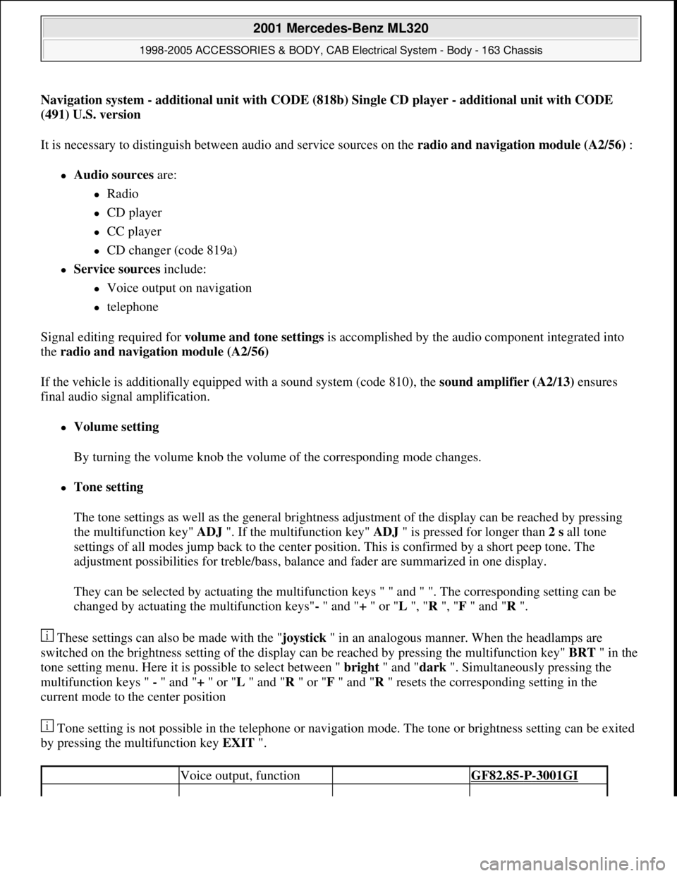
Navigation system - additional unit with CODE (818b) Single CD player - additional unit with CODE
(491) U.S. version
It is necessary to distinguish between audio and service sources on the radio and navigation module (A2/56) :
Audio sources are:
Radio
CD player
CC player
CD changer (code 819a)
Service sources include:
Voice output on navigation
telephone
Signal editing required for volume and tone settings is accomplished by the audio component integrated into
the radio and navigation module (A2/56)
If the vehicle is additionally equipped with a sound system (code 810), the sound amplifier (A2/13) ensures
final audio signal amplification.
Volume setting
By turning the volume knob the volume of the corresponding mode changes.
Tone setting
The tone settings as well as the general brightness adjustment of the display can be reached by pressing
the multifunction key" ADJ ". If the multifunction key" ADJ " is pressed for longer than 2 s all tone
settings of all modes jump back to the center position. This is confirmed by a short peep tone. The
adjustment possibilities for treble/bass, balance and fader are summarized in one display.
They can be selected by actuating the multifunction keys " " and " ". The corresponding setting can be
changed by actuating the multifunction keys"- " and "+ " or "L ", "R ", "F " and "R ".
These settings can also be made with the "joystick " in an analogous manner. When the headlamps are
switched on the brightness setting of the display can be reached by pressing the multifunction key" BRT" in the
tone setting menu. Here it is possible to select between " bright " and "dark ". Simultaneously pressing the
multifunction keys " - " and "+ " or "L " and "R " or "F " and "R " resets the corresponding setting in the
current mode to the center position
Tone setting is not possible in the telephone or navigation mode. The tone or brightness setting can be exited
by pressing the multifunction key EXIT ".
Voice output, function GF82.85-P-3001GI
2001 Mercedes-Benz ML320
1998-2005 ACCESSORIES & BODY, CAB Electrical System - Body - 163 Chassis
me
Saturday, October 02, 2010 3:30:05 PMPage 68 © 2006 Mitchell Repair Information Company, LLC.
Page 1567 of 4133
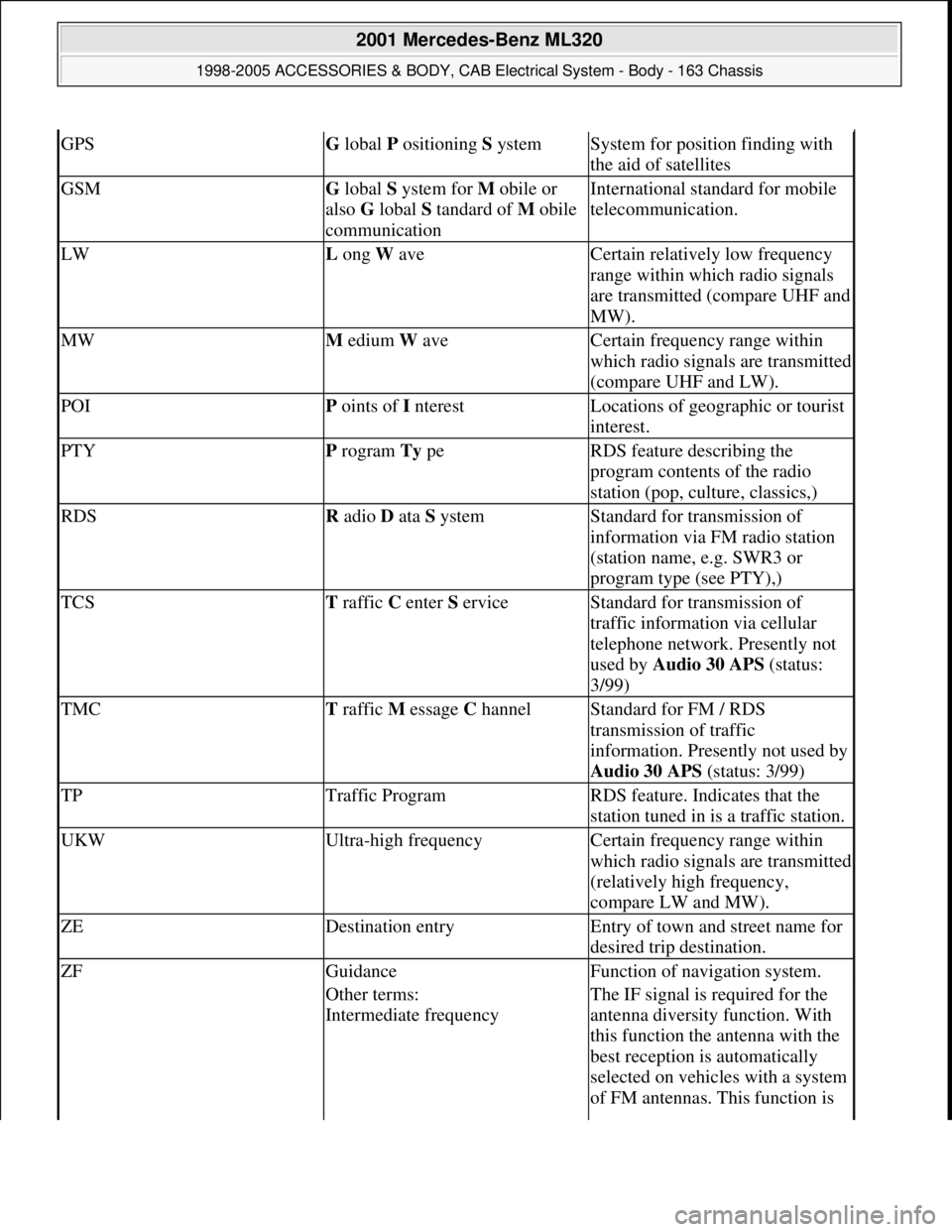
GPSG lobal P ositioning S ystemSystem for position finding with
the aid of satellites
GSMG lobal S ystem for M obile or
also G lobal S tandard of M obile
communicationInternational standard for mobile
telecommunication.
LWL ong W aveCertain relatively low frequency
range within which radio signals
are transmitted (compare UHF and
MW).
MWM edium W aveCertain frequency range within
which radio signals are transmitted
(compare UHF and LW).
POIP oints of I nterestLocations of geographic or tourist
interest.
PTYP rogram Ty peRDS feature describing the
program contents of the radio
station (pop, culture, classics,)
RDSR adio D ata S ystemStandard for transmission of
information via FM radio station
(station name, e.g. SWR3 or
program type (see PTY),)
TCST raffic C enter S erviceStandard for transmission of
traffic information via cellular
telephone network. Presently not
used by Audio 30 APS (status:
3/99)
TMCT raffic M essage C hannelStandard for FM / RDS
transmission of traffic
information. Presently not used by
Audio 30 APS (status: 3/99)
TPTraffic ProgramRDS feature. Indicates that the
station tuned in is a traffic station.
UKWUltra-high frequencyCertain frequency range within
which radio signals are transmitted
(relatively high frequency,
compare LW and MW).
ZEDestination entryEntry of town and street name for
desired trip destination.
ZFGuidanceFunction of navigation system.
Other terms:
Intermediate frequencyThe IF signal is required for the
antenna diversity function. With
this function the antenna with the
best reception is automatically
selected on vehicles with a system
of FM antennas. This function is
2001 Mercedes-Benz ML320
1998-2005 ACCESSORIES & BODY, CAB Electrical System - Body - 163 Chassis
me
Saturday, October 02, 2010 3:30:05 PMPage 72 © 2006 Mitchell Repair Information Company, LLC.
Page 1569 of 4133
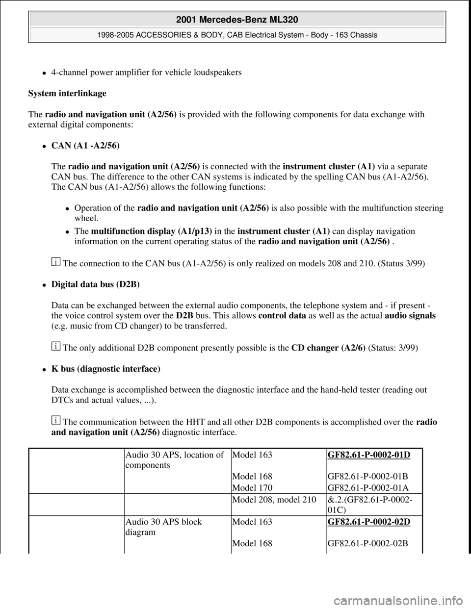
4-channel power amplifier for vehicle loudspeakers
System interlinkage
The radio and navigation unit (A2/56) is provided with the following components for data exchange with
external digital components:
CAN (A1 -A2/56)
The radio and navigation unit (A2/56) is connected with the instrument cluster (A1) via a separate
CAN bus. The difference to the other CAN systems is indicated by the spelling CAN bus (A1-A2/56).
The CAN bus (A1-A2/56) allows the following functions:
Operation of the radio and navigation unit (A2/56)is also possible with the multifunction steering
wheel.
The multifunction display (A1/p13) in the instrument cluster (A1) can display navigation
information on the current operating status of the radio and navigation unit (A2/56) .
The connection to the CAN bus (A1-A2/56) is only realized on models 208 and 210. (Status 3/99)
Digital data bus (D2B)
Data can be exchanged between the external audio components, the telephone system and - if present -
the voice control system over the D2B bus. This allows control data as well as the actual audio signals
(e.g. music from CD changer) to be transferred.
The only additional D2B component presently possible is the CD changer (A2/6) (Status: 3/99)
K bus (diagnostic interface)
Data exchange is accomplished between the diagnostic interface and the hand-held tester (reading out
DTCs and actual values, ...).
The communication between the HHT and all other D2B components is accomplished over the radio
and navigation unit (A2/56) diagnostic interface.
Audio 30 APS, location of
componentsModel 163GF82.61-P-0002-01D
Model 168GF82.61-P-0002-01B
Model 170GF82.61-P-0002-01A
Model 208, model 210&.2.(GF82.61-P-0002-
01C)
Audio 30 APS block
diagramModel 163GF82.61-P-0002-02D
Model 168GF82.61-P-0002-02B
2001 Mercedes-Benz ML320
1998-2005 ACCESSORIES & BODY, CAB Electrical System - Body - 163 Chassis
me
Saturday, October 02, 2010 3:30:05 PMPage 74 © 2006 Mitchell Repair Information Company, LLC.
Page 1571 of 4133
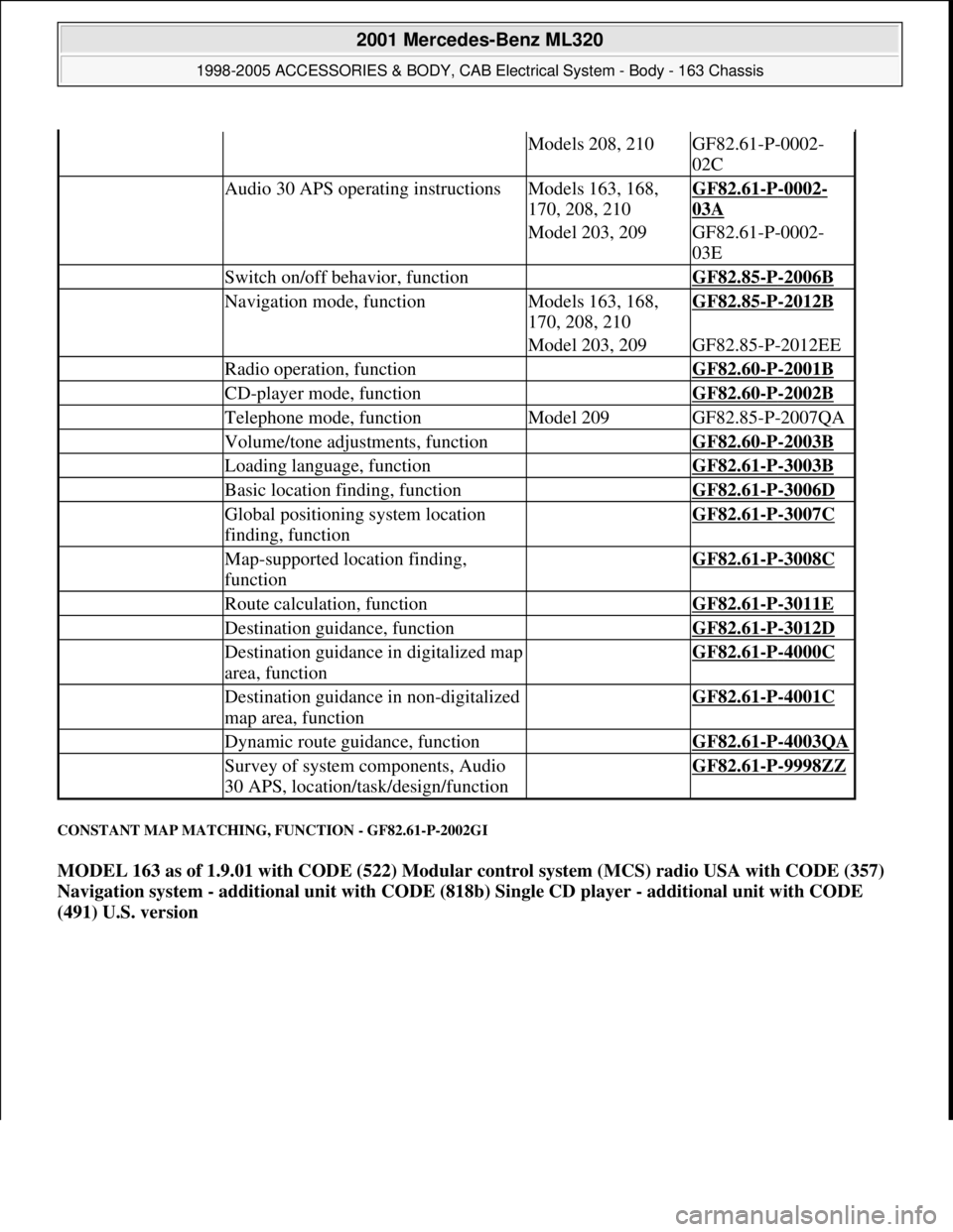
CONSTANT MAP MATCHING, FUNCTION - GF82.61-P-2002GI
MODEL 163 as of 1.9.01 with CODE (522) Modular control system (MCS) radio USA with CODE (357)
Navigation system - additional unit with CODE (818b) Single CD player - additional unit with CODE
(491) U.S. version
Models 208, 210GF82.61-P-0002-
02C
Audio 30 APS operating instructionsModels 163, 168,
170, 208, 210GF82.61-P-0002-
03A
Model 203, 209GF82.61-P-0002-
03E
Switch on/off behavior, function GF82.85-P-2006B
Navigation mode, functionModels 163, 168,
170, 208, 210GF82.85-P-2012B
Model 203, 209GF82.85-P-2012EE
Radio operation, function GF82.60-P-2001B
CD-player mode, function GF82.60-P-2002B
Telephone mode, functionModel 209GF82.85-P-2007QA
Volume/tone adjustments, function GF82.60-P-2003B
Loading language, function GF82.61-P-3003B
Basic location finding, function GF82.61-P-3006D
Global positioning system location
finding, function GF82.61-P-3007C
Map-supported location finding,
function GF82.61-P-3008C
Route calculation, function GF82.61-P-3011E
Destination guidance, function GF82.61-P-3012D
Destination guidance in digitalized map
area, function GF82.61-P-4000C
Destination guidance in non-digitalized
map area, function GF82.61-P-4001C
Dynamic route guidance, function GF82.61-P-4003QA
Survey of system components, Audio
30 APS, location/task/design/function GF82.61-P-9998ZZ
2001 Mercedes-Benz ML320
1998-2005 ACCESSORIES & BODY, CAB Electrical System - Body - 163 Chassis
me
Saturday, October 02, 2010 3:30:05 PMPage 76 © 2006 Mitchell Repair Information Company, LLC.
Page 1578 of 4133
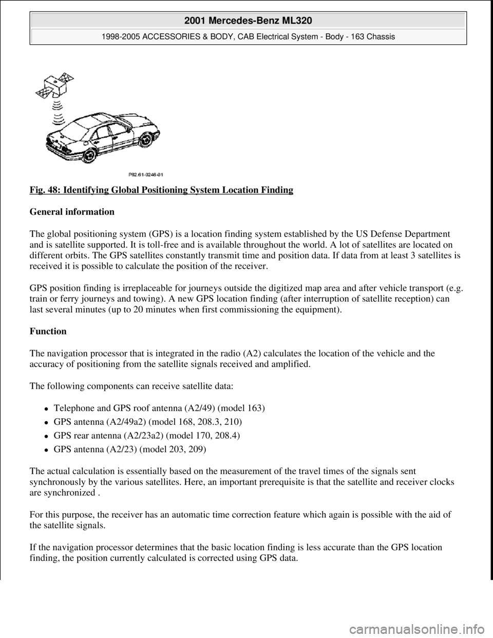
Fig. 48: Identifying Global Positioning System Location Finding
General information
The global positioning system (GPS) is a location finding system established by the US Defense Department
and is satellite supported. It is toll-free and is available throughout the world. A lot of satellites are located on
different orbits. The GPS satellites constantly transmit time and position data. If data from at least 3 satellites is
received it is possible to calculate the position of the receiver.
GPS position finding is irreplaceable for journeys outside the digitized map area and after vehicle transport (e.g.
train or ferry journeys and towing). A new GPS location finding (after interruption of satellite reception) can
last several minutes (up to 20 minutes when first commissioning the equipment).
Function
The navigation processor that is integrated in the radio (A2) calculates the location of the vehicle and the
accuracy of positioning from the satellite signals received and amplified.
The following components can receive satellite data:
Telephone and GPS roof antenna (A2/49) (model 163)
GPS antenna (A2/49a2) (model 168, 208.3, 210)
GPS rear antenna (A2/23a2) (model 170, 208.4)
GPS antenna (A2/23) (model 203, 209)
The actual calculation is essentially based on the measurement of the travel times of the signals sent
synchronously by the various satellites. Here, an important prerequisite is that the satellite and receiver clocks
are synchronized .
For this purpose, the receiver has an automatic time correction feature which again is possible with the aid of
the satellite signals.
If the navigation processor determines that the basic location finding is less accurate than the GPS location
findin
g, the position currently calculated is corrected using GPS data.
2001 Mercedes-Benz ML320
1998-2005 ACCESSORIES & BODY, CAB Electrical System - Body - 163 Chassis
me
Saturday, October 02, 2010 3:30:05 PMPage 83 © 2006 Mitchell Repair Information Company, LLC.
Page 1580 of 4133
and is available worldwide . Presently there are 266 satellites on 6 different earth orbits. The GPSsatellites
permanently transmit time and position data. If data from a minimum of 3 satellites is received (with two-
dimensional location finding) it is possible to calculate the position of the receiver.
The GPS location finding is particularly important when driving outside of the digitized map area and
following vehicle transport (e.g. train, ferry or towing).
A repeated GPS location finding (following satellite reception interruption) can take several minutes (when
unit is initially started up to 20 min .).
GPS map matching function
The navigation processor calculates the location of the vehicle and the accuracy of positioning from the
satellite signals received and amplified by the GPS antenna (A2/49) . The current calculation is based
primarily on the measurement of the transmission times for the signals transmitted synchronously by the
various satellites. Here, an important prerequisite is that the satellite and receiver clocks are synchronized . For
this purpose, the receiver has an automatic time correction feature which again is possible with the aid of the
satellite signals. If the navigation processor determines that the basic location finding is less precise than the
GPS location finding, the currently calculated position is corrected with the aid of the GPS data .
Moreover, the vehicle route is determined from the location sequence calculated with GPS .
Approx. 50 new GPS location finding calculations are performed each minute.
Possible interference when receiving GPS signals
Since GPS operates in the GHz (microwave) range and the signals are weak, reception interferences can
occur from
atmospheric interferences, e.g. weather, water vapor, fog,
multiple path reception due to signal reflections, e.g. from building walls
Signal shadows, e.g. in built-up areas, tunnels, high buildings, trees
A free view of the sky is therefore necessary for GPS reception The location finding accuracy is approx. 100
m or better .
Basic location finding,
function GF82.61-P-3006GI
Map-supported location
finding, function GF82.61-P-3008GI
Guidance, function GF82.61-P-3012GI
Radio and navigation
module, location/purpose/
design/function GF82.61-P-4109GI
GPS roof antenna/telephone, GF82.70-P-4111A
2001 Mercedes-Benz ML320
1998-2005 ACCESSORIES & BODY, CAB Electrical System - Body - 163 Chassis
me
Saturday, October 02, 2010 3:30:05 PMPage 85 © 2006 Mitchell Repair Information Company, LLC.