phone MERCEDES-BENZ ML350 1997 Complete Manual PDF
[x] Cancel search | Manufacturer: MERCEDES-BENZ, Model Year: 1997, Model line: ML350, Model: MERCEDES-BENZ ML350 1997Pages: 4133, PDF Size: 88.89 MB
Page 1592 of 4133
DYNAMIC ROUTE GUIDANCE, FUNCTION - GF82.61-P-4003QA
MODEL 163, 168, 170, 203.0 /2 /7, 208, 209.3 /4, 210 with CODE (353) Audio 30 APS
The current traffic situation is taken into consideration in the dynamic route guidance. The COMAND
navigation system Audio 30 APS can receive information on the traffic situation either by the Traffic Center
Service (TCS) or the Traffic Message Channel (TMC).
The services from the Traffic Center Service (TCS) are offered by an external provider and an application is
to be sent to the provider for use.
Traffic messages via Traffic Center Service (TCS)
The latest traffic situation information is transmitted by a service provider for a fee in the form of an SMS (short
message service) signal via the CTEL D network. The traffic data are only transmitted when the service
provider receives a corresponding request from the vehicle.
The request can be sent either:
Cyclically, every 15 minutes
Once
In order to reduce the data volume the current location of the vehicle is automatically sent to the D network
center when the information request is posted.
The service provider then transmits only traffic messages at within a radius of approx. 75 km of the vehicle. The
telephone system of the vehicle receives the traffic announcements and transmits them via the D2B to the traffic
data recorder that is integrated in the radio (A2).
It is possible to use the telephone during TCS data interchange.
Traffic messages via Traffic Message Channel (TMC)
Information on the current traffic situation is transmitted by a specially equipped radio-broadcast station aimed
at specific areas and coded (toll) or uncoded (toll free) via VHF. For this purpose an appropriate FM/ RDS
station must be tuned in.
The radio (A2) receives the traffic announcements and transmits them to the traffic data recorder. Since no
communication is accomplished between the vehicle and broadcasting corporation with TMC messages, the
traffic data recorder selects the traffic messa
ges related to the route on which the vehicle is presently driving as
Starguide, function GF82.85-P-2014GI
Information service,
function GF82.85-P-3016GI
Data transmission for
Starguide, function GF82.85-P-3017GI
2001 Mercedes-Benz ML320
1998-2005 ACCESSORIES & BODY, CAB Electrical System - Body - 163 Chassis
me
Saturday, October 02, 2010 3:30:05 PMPage 97 © 2006 Mitchell Repair Information Company, LLC.
Page 1593 of 4133
well as the surrounding area.
Traffic information analysis
In both cases (TCS or TMC) the traffic data recorder decodes the traffic information and forwards it when
requested to the navigation computer. The navigation processor makes the decision whether the route should be
changed. If necessary, a message that the route should be changed is output via the vehicle speaker.
For synchronization purposes the traffic data recorder needs a list from the navigation processor, in which each
stretch and each striking feature (e.g., freeway exit) of the recorded street network is clearly defined with the aid
of a number. The list is originally stored on DVD. If required (e.g. changing the DVD) it is automatically
loaded into the traffic data recorder. The traffic information stored in the traffic data recorder is erased
automatically after 0.5 hrs., max. 100 messages can be stored.
The decoded traffic messages are marked on the map using suitable symbols. They can also be displayed as
clear text. To this end the "alternate route" button should be pressed and the "TRAFFIC INFO" menu activated.
RADIO AND NAVIGATION UNIT, LOCATION - GF82.61-P-4109-01A
Models 163, 168, 170,208, 210 with code 353
Radio/navigation unit
location/task/design/ functionModels 163, 168,
170, 208, 210GF82.61-P-4109A
Model 209GF82.61-P-4109QA
Radio, location/task/design/functionModel 203GF82.60-P-4109P
Transmitter/receiver unit,
location/task/design/ functionModel 203, 210
with code (853) MB
standard telephone
with code (855)
TELE AID
with code (930) taxi
emergency call
Model 209
with code (853) MB
standard telephone
with code (855)
TELE AIDGF82.95-P-4300A
Telephone interface,
location/task/design/ functionModel 203, 209GF82.70-P-3107Q
2001 Mercedes-Benz ML320
1998-2005 ACCESSORIES & BODY, CAB Electrical System - Body - 163 Chassis
me
Saturday, October 02, 2010 3:30:05 PMPage 98 © 2006 Mitchell Repair Information Company, LLC.
Page 1595 of 4133
RADIO AND NAVIGATION MODULE, DESIGN - GF82.61-P-4109-03GI
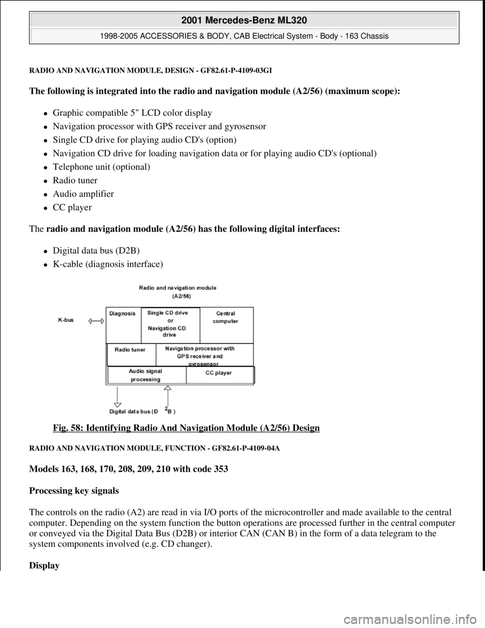
The following is integrated into the radio and navigation module (A2/56) (maximum scope):
Graphic compatible 5" LCD color display
Navigation processor with GPS receiver and gyrosensor
Single CD drive for playing audio CD's (option)
Navigation CD drive for loading navigation data or for playing audio CD's (optional)
Telephone unit (optional)
Radio tuner
Audio amplifier
CC player
The radio and navigation module (A2/56) has the following digital interfaces:
Digital data bus (D2B)
K-cable (diagnosis interface)
Fig. 58: Identifying Radio And Navigation Module (A2/56) Design
RADIO AND NAVIGATION MODULE, FUNCTION - GF82.61-P-4109-04A
Models 163, 168, 170, 208, 209, 210 with code 353
Processing key signals
The controls on the radio (A2) are read in via I/O ports of the microcontroller and made available to the central
computer. Depending on the system function the button operations are processed further in the central computer
or conveyed via the Digital Data Bus (D2B) or interior CAN (CAN B) in the form of a data telegram to the
system components involved (e.g. CD changer).
Display
2001 Mercedes-Benz ML320
1998-2005 ACCESSORIES & BODY, CAB Electrical System - Body - 163 Chassis
me
Saturday, October 02, 2010 3:30:05 PMPage 100 © 2006 Mitchell Repair Information Company, LLC.
Page 1596 of 4133
The display of the radios (A2) has 197 x 32 pixels. Texts are displayed in 3 lines.
After particular functions are called (e.g. navigation), the bottom line shows a variable inscription for the row of
buttons underneath (multifunction buttons). As a result the system can be operated very conveniently with a few
buttons, as the function which is activated when the button is operated, is shown in plain text (e.g. LANG,
ITEM, DYN, CLOCK etc.).
Audio signal output
The audio signals of the various sources (CD, voice output for navigation etc.) are processed by the radio (A2)
and amplified before output by the vehicle speakers.
On models 168, 170, 208 and 210 with the sound system (code 810) the audio signals are finally amplified
by the amplifier for the sound system (N40/3). For this, the audio source data (low-frequency signals) are
transmitted to the amplifier for the sound system (N40/3) via separate lines.
On models 163 and 209 the final amplification of the audio signal is performed by the sound amplifier
(A2/13). All the data are transmitted via the D2B.
Audio mute
An incoming phone call activates the audio mute function (a separate signal input exists on the radio (A2) for
this). When the audio mute function is activated, the current audio source (e.g. radio) is muted automatically.
Navigation processor, GPS control module and gyrosensor
The navigation processor is the central component of the navigation system.
It is integrated into the radio (A2) and from the incoming signals continuously calculates the location and once
the destination is entered calculates the route for navigation. The GPS receiver is integrated into the navigation
processor. It evaluates the satellite signals and calculates from them the vehicle position in degrees longitude
and latitude. Various GPS antennae are used to receive these signals depending on the vehicle model:
Model 163: telephone and GPS roof antenna (A2/49)
Models 168, 208.3, 210: GPS antenna (A2/49a2)
Models 170, 208.4: GPS rear antenna (A2/23a2)
Model 209: GPS antenna (A2/23)
Reception from at least 3 satellites is necessary for exact GPS position calculation. A free view of the sky is
required for this purpose.
The integrated gyrosensor continuously senses every change in direction of the vehicle. Evaluation of this data
is accomplished by the navigation processor.
Calibration of the gyrosensor is not required.
2001 Mercedes-Benz ML320
1998-2005 ACCESSORIES & BODY, CAB Electrical System - Body - 163 Chassis
me
Saturday, October 02, 2010 3:30:05 PMPage 101 © 2006 Mitchell Repair Information Company, LLC.
Page 1601 of 4133
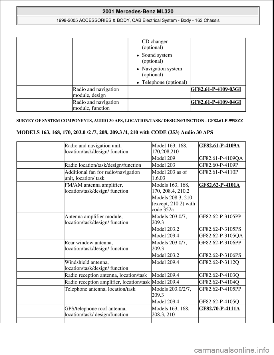
SURVEY OF SYSTEM COMPONENTS, AUDIO 30 APS, LOCATION/TASK/ DESIGN/FUNCTION - GF82.61-P-9998ZZ
MODELS 163, 168, 170, 203.0 /2 /7, 208, 209.3 /4, 210 with CODE (353) Audio 30 APS
CD changer
(optional)
Sound system
(optional)
Navigation system
(optional)
Telephone (optional)
Radio and navigation
module, design GF82.61-P-4109-03GI
Radio and navigation
module, function GF82.61-P-4109-04GI
Radio and navigation unit,
location/task/design/ functionModel 163, 168,
170,208,210GF82.61-P-4109A
Model 209GF82.61-P-4109QA
Radio location/task/design/functionModel 203GF82.60-P-4109P
Additional fan for radio/navigation
unit, location/ taskModel 203 as of
1.6.03GF82.61-P-4110P
FM/AM antenna amplifier,
location/task/design/ functionModels 163, 168,
170, 208.4, 210.2GF82.62-P-4101A
Models 208.3, 210
(except, 210.2) with
code 352a
Antenna amplifier module,
location/task/design/ functionModels 203.0/7,
209.3GF82.62-P-3105PP
Model 203.2GF82.62-P-3105PS
Model 209.4GF82.62-P-3105QA
Rear window antenna,
location/task/design/ functionModels 203.0/7,
209.3GF82.62-P-3106PP
Model 203.2GF82.62-P-3106PS
Windshield antenna,
location/task/design/ functionModel 209.4GF82.62-P-3112Q
Radio reception antenna, location/taskModel 209.4GF82.62-P-4103Q
Radio reception amplifier, location/taskModel 209.4GF82.62-P-4104Q
Telephone antenna, location/taskModels 203.0/2/7,
209.3GF82.62-P-4105PP
Model 209.4GF82.62-P-4105Q
GPS/telephone roof antenna,
location/task/ design/functionModels 163, 168,
208.3, 210GF82.70-P-4111A
2001 Mercedes-Benz ML320
1998-2005 ACCESSORIES & BODY, CAB Electrical System - Body - 163 Chassis
me
Saturday, October 02, 2010 3:30:05 PMPage 106 © 2006 Mitchell Repair Information Company, LLC.
Page 1602 of 4133
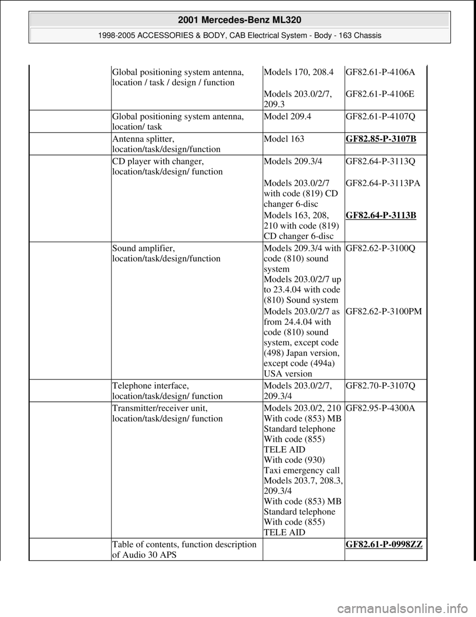
Global positioning system antenna,
location / task / design / functionModels 170, 208.4GF82.61-P-4106A
Models 203.0/2/7,
209.3GF82.61-P-4106E
Global positioning system antenna,
location/ taskModel 209.4GF82.61-P-4107Q
Antenna splitter,
location/task/design/functionModel 163GF82.85-P-3107B
CD player with changer,
location/task/design/ functionModels 209.3/4GF82.64-P-3113Q
Models 203.0/2/7
with code (819) CD
changer 6-discGF82.64-P-3113PA
Models 163, 208,
210 with code (819)
CD changer 6-discGF82.64-P-3113B
Sound amplifier,
location/task/design/functionModels 209.3/4 with
code (810) sound
system
Models 203.0/2/7 up
to 23.4.04 with code
(810) Sound systemGF82.62-P-3100Q
Models 203.0/2/7 as
from 24.4.04 with
code (810) sound
system, except code
(498) Japan version,
except code (494a)
USA versionGF82.62-P-3100PM
Telephone interface,
location/task/design/ functionModels 203.0/2/7,
209.3/4GF82.70-P-3107Q
Transmitter/receiver unit,
location/task/design/ functionModels 203.0/2, 210
With code (853) MB
Standard telephone
With code (855)
TELE AID
With code (930)
Taxi emergency call
Models 203.7, 208.3,
209.3/4
With code (853) MB
Standard telephone
With code (855)
TELE AIDGF82.95-P-4300A
Table of contents, function description
of Audio 30 APS GF82.61-P-0998ZZ
2001 Mercedes-Benz ML320
1998-2005 ACCESSORIES & BODY, CAB Electrical System - Body - 163 Chassis
me
Saturday, October 02, 2010 3:30:05 PMPage 107 © 2006 Mitchell Repair Information Company, LLC.
Page 1609 of 4133
analog filters, digital filters contain the following significant advantages:
the filter parameters (sound settings) do not alter throughout the period, this thus means that all the
settings can be repeated exactly
low noise level
the component outlay is significantly reduced, as the filter parameters are set by the software and not by
varying component values (resistances, capacitances or inductance values), thus the number of possible
filter settings is increased
Sound optimizations
Each of the six amplifier channels is equipped with an individual compensation, which can, when requested,
rectify the vehicle's acoustics. In addition further sound optimization settings can be made and effects such as,
e.g. 'voice emphasizing' or 'stereoscopic sound' invoked.
Bass, treble, volume, balance, fader and the dynamic loudness function can be individually set.
Noise suppression
The output level of the six 6 output stages is constantly monitored and regulated such that distortion is kept to a
minimum.
Automatic Vehicle Noise Compensation (VNC))
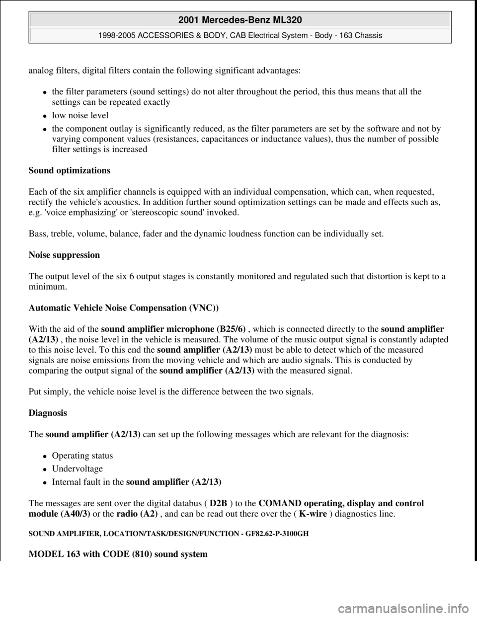
With the aid of the sound amplifier microphone (B25/6) , which is connected directly to the sound amplifier
(A2/13) , the noise level in the vehicle is measured. The volume of the music output signal is constantly adapted
to this noise level. To this end the sound amplifier (A2/13) must be able to detect which of the measured
signals are noise emissions from the moving vehicle and which are audio signals. This is conducted by
comparing the output signal of the sound amplifier (A2/13) with the measured signal.
Put simply, the vehicle noise level is the difference between the two signals.
Diagnosis
The sound amplifier (A2/13) can set up the following messages which are relevant for the diagnosis:
Operating status
Undervoltage
Internal fault in the sound amplifier (A2/13)
The messages are sent over the digital databus ( D2B ) to the COMAND operating, display and control
module (A40/3) or the radio (A2) , and can be read out there over the ( K-wire ) diagnostics line.
SOUND AMPLIFIER, LOCATION/TASK/DESIGN/FUNCTION - GF82.62-P-3100GH
MODEL 163 with CODE (810) sound system
2001 Mercedes-Benz ML320
1998-2005 ACCESSORIES & BODY, CAB Electrical System - Body - 163 Chassis
me
Saturday, October 02, 2010 3:30:06 PMPage 114 © 2006 Mitchell Repair Information Company, LLC.
Page 1610 of 4133
REAR WINDOW ANTENNAS, DESIGN - GF82.62-P-3106-03GH
Model 163
Antenna ranges
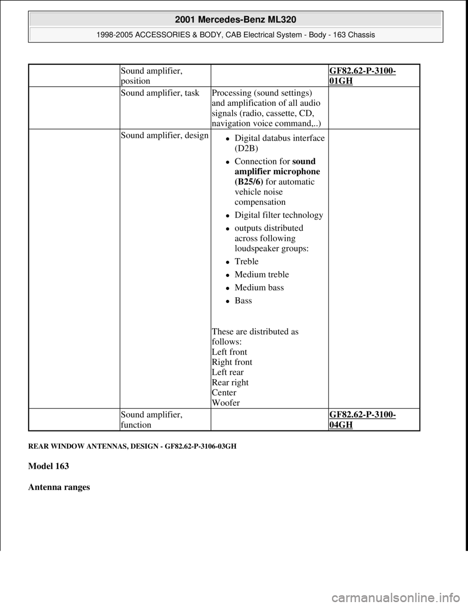
Sound amplifier,
position GF82.62-P-3100-
01GH
Sound amplifier, taskProcessing (sound settings)
and amplification of all audio
signals (radio, cassette, CD,
navigation voice command,..)
Sound amplifier, designDigital databus interface
(D2B)
Connection for sound
amplifier microphone
(B25/6) for automatic
vehicle noise
compensation
Digital filter technology
outputs distributed
across following
loudspeaker groups:
Treble
Medium treble
Medium bass
Bass
These are distributed as
follows:
Left front
Right front
Left rear
Rear right
Center
Woofer
Sound amplifier,
function GF82.62-P-3100-
04GH
2001 Mercedes-Benz ML320
1998-2005 ACCESSORIES & BODY, CAB Electrical System - Body - 163 Chassis
me
Saturday, October 02, 2010 3:30:06 PMPage 115 © 2006 Mitchell Repair Information Company, LLC.
Page 1614 of 4133
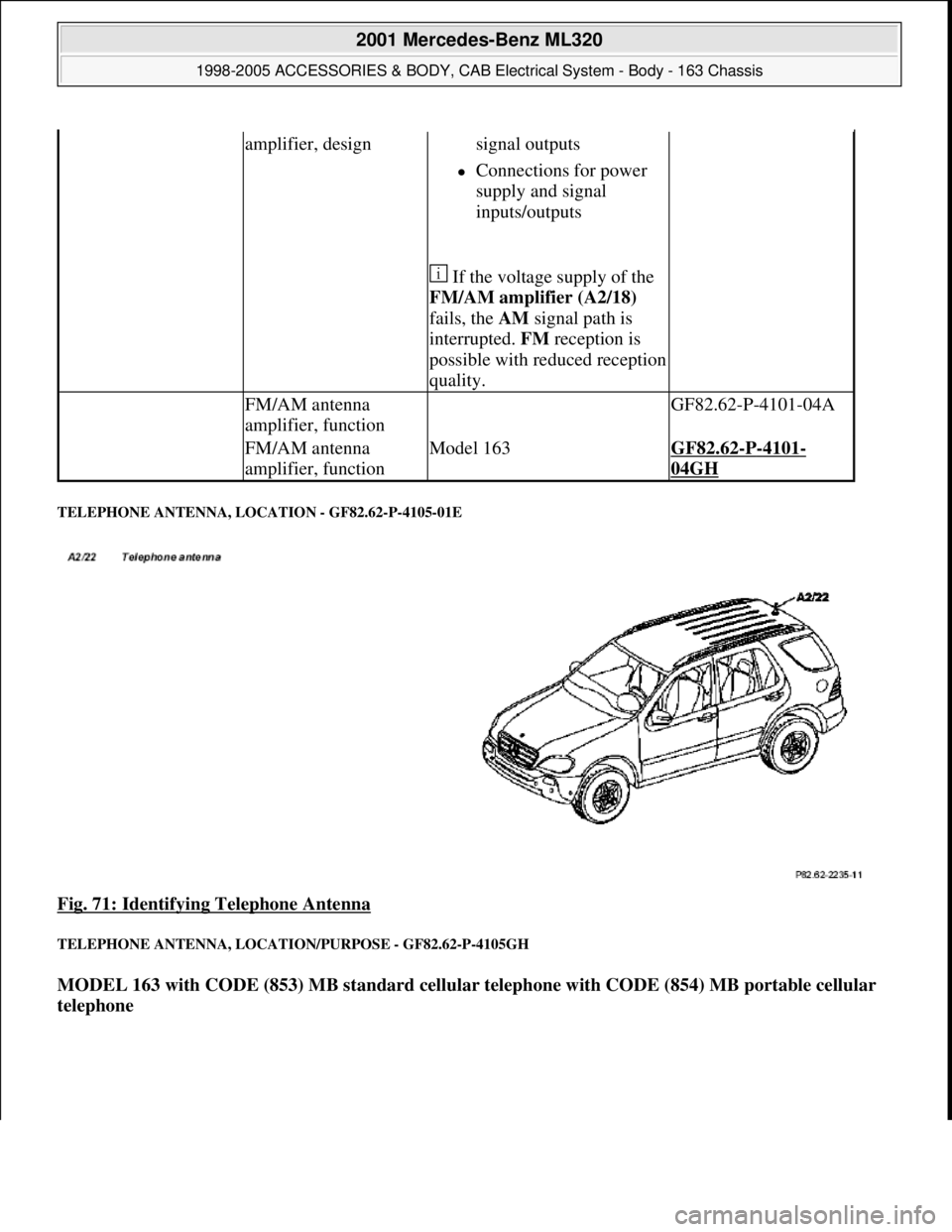
TELEPHONE ANTENNA, LOCATION - GF82.62-P-4105-01E
Fig. 71: Identifying Telephone Antenna
TELEPHONE ANTENNA, LOCATION/PURPOSE - GF82.62-P-4105GH
MODEL 163 with CODE (853) MB standard cellular telephone with CODE (854) MB portable cellular
telephone
amplifier, designsignal outputs
Connections for power
supply and signal
inputs/outputs
If the voltage supply of the
FM/AM amplifier (A2/18)
fails, the AM signal path is
interrupted. FM reception is
possible with reduced reception
quality.
FM/AM antenna
amplifier, function GF82.62-P-4101-04A
FM/AM antenna
amplifier, functionModel 163GF82.62-P-4101-
04GH
2001 Mercedes-Benz ML320
1998-2005 ACCESSORIES & BODY, CAB Electrical System - Body - 163 Chassis
me
Saturday, October 02, 2010 3:30:06 PMPage 119 © 2006 Mitchell Repair Information Company, LLC.
Page 1615 of 4133
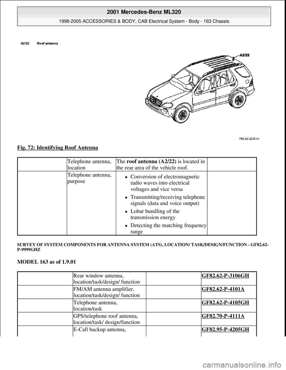
Fig. 72: Identifying Roof Antenna
SURVEY OF SYSTEM COMPONENTS FOR ANTENNA SYSTEM (ATS), LOCATION/ TASK/DESIGN/FUNCTION - GF82.62-
P-9999GHZ
MODEL 163 as of 1.9.01
Telephone antenna,
locationThe roof antenna (A2/22) is located in
the rear area of the vehicle roof.
Telephone antenna,
purposeConversion of electromagnetic
radio waves into electrical
voltages and vice versa
Transmitting/receiving telephone
signals (data and voice output)
Lobar bundling of the
transmission energy
Detecting the matching frequency
range
Rear window antenna,
location/task/design/ function GF82.62-P-3106GH
FM/AM antenna amplifier,
location/task/design/ function GF82.62-P-4101A
Telephone antenna,
location/task GF82.62-P-4105GH
GPS/telephone roof antenna,
location/task/ design/function GF82.70-P-4111A
E-Call backup antenna, GF82.95-P-4205GH
2001 Mercedes-Benz ML320
1998-2005 ACCESSORIES & BODY, CAB Electrical System - Body - 163 Chassis
me
Saturday, October 02, 2010 3:30:06 PMPage 120 © 2006 Mitchell Repair Information Company, LLC.