AUX MERCEDES-BENZ ML350 1997 Complete Manual PDF
[x] Cancel search | Manufacturer: MERCEDES-BENZ, Model Year: 1997, Model line: ML350, Model: MERCEDES-BENZ ML350 1997Pages: 4133, PDF Size: 88.89 MB
Page 3323 of 4133
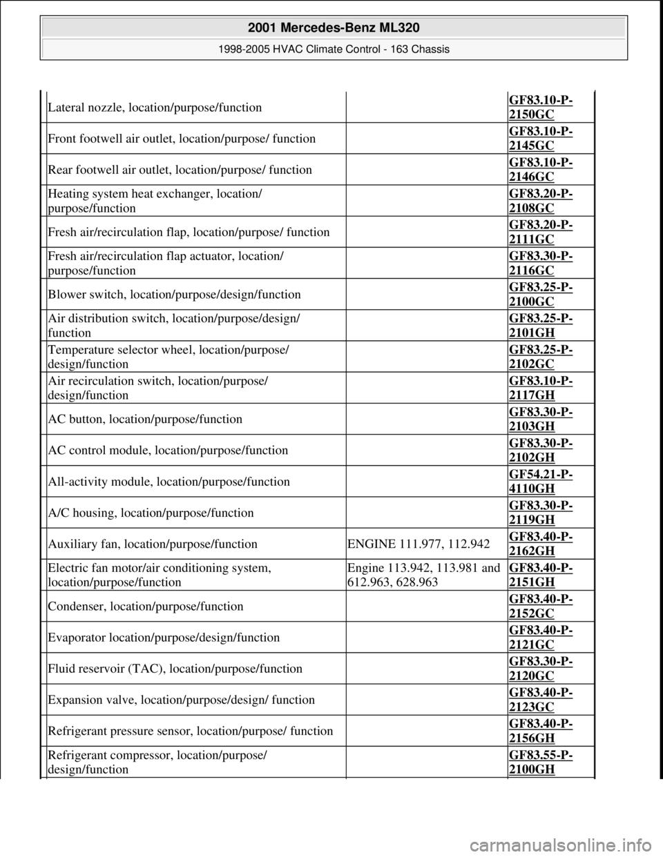
Lateral nozzle, location/purpose/function GF83.10-P-
2150GC
Front footwell air outlet, location/purpose/ function GF83.10-P-
2145GC
Rear footwell air outlet, location/purpose/ function GF83.10-P-
2146GC
Heating system heat exchanger, location/
purpose/function GF83.20-P-
2108GC
Fresh air/recirculation flap, location/purpose/ function GF83.20-P-
2111GC
Fresh air/recirculation flap actuator, location/
purpose/function GF83.30-P-
2116GC
Blower switch, location/purpose/design/function GF83.25-P-
2100GC
Air distribution switch, location/purpose/design/
function GF83.25-P-
2101GH
Temperature selector wheel, location/purpose/
design/function GF83.25-P-
2102GC
Air recirculation switch, location/purpose/
design/function GF83.10-P-
2117GH
AC button, location/purpose/function GF83.30-P-
2103GH
AC control module, location/purpose/function GF83.30-P-
2102GH
All-activity module, location/purpose/function GF54.21-P-
4110GH
A/C housing, location/purpose/function GF83.30-P-
2119GH
Auxiliary fan, location/purpose/functionENGINE 111.977, 112.942GF83.40-P-
2162GH
Electric fan motor/air conditioning system,
location/purpose/functionEngine 113.942, 113.981 and
612.963, 628.963GF83.40-P-
2151GH
Condenser, location/purpose/function GF83.40-P-
2152GC
Evaporator location/purpose/design/function GF83.40-P-
2121GC
Fluid reservoir (TAC), location/purpose/function GF83.30-P-
2120GC
Expansion valve, location/purpose/design/ function GF83.40-P-
2123GC
Refrigerant pressure sensor, location/purpose/ function GF83.40-P-
2156GH
Refrigerant compressor, location/purpose/
design/function GF83.55-P-
2100GH
2001 Mercedes-Benz ML320
1998-2005 HVAC Climate Control - 163 Chassis
me
Saturday, October 02, 2010 3:23:15 PMPage 79 © 2006 Mitchell Repair Information Company, LLC.
Page 3328 of 4133
The control module integrated in the AAC push-button control module (N22) looks after all system regulation
and control functions such as:
comparing preselected and actual temperatures and controlling the air temperature at the air outlets
automatic switchover from fresh air to recirculated air mode
electrical control of refrigerant compressor
controlling the auxiliary fan or the electric suction-type fan motor/ air conditioning with integrated
control
The AAC push-button control module (N22) has a diagnostic capability. Consequently, any faults which occur
are stored in the fault memory which can be read with the help of the diagnosis assistant system (DAS).
When the AAC push-button control module is replaced (N22), variant coding must be carried out using the
Diagnosis Assistant System (DAS).
The AAC push-button control module (N22) also performs the following actuations:
direct: refrigerant compressor; heating water circulation pump; PTC heater booster (OM 612 only), rear
window heater
via the CAN BUS: auxiliary fan, electric suction-type fan motor/air conditioning with integrated control,
blower control and air distribution in the rear compartment (automatic mode)
via the AC bus: blower motor; 8 stepping motors for air distribution
The following sensor signals are read in by the AAC push-button control module (N22):
direct: temperature sensor evaporator, pressure and temperature sensor refrigerant, in-car temperature
sensor, center nozzle vent air temperature sensor, footwell and rear passenger compartment, sun sensor
via the CAN BUS: Ambient temperature display temperature sensor, sensor for specified values in rear
control panel
REFRIGERANT CIRCUIT FUNCTION - GF83.40-P-2001GH
MODEL 163 up to 31.8.01 with CODE (580) Air conditioning or Tempmatic for USA
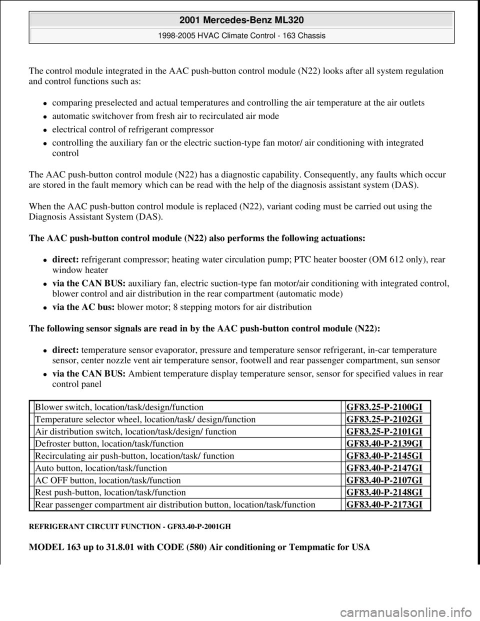
Blower switch, location/task/design/function GF83.25-P-2100GI
Temperature selector wheel, location/task/ design/function GF83.25-P-2102GI
Air distribution switch, location/task/design/ function GF83.25-P-2101GI
Defroster button, location/task/function GF83.40-P-2139GI
Recirculating air push-button, location/task/ function GF83.40-P-2145GI
Auto button, location/task/function GF83.40-P-2147GI
AC OFF button, location/task/function GF83.40-P-2107GI
Rest push-button, location/task/function GF83.40-P-2148GI
Rear passenger compartment air distribution button, location/task/function GF83.40-P-2173GI
2001 Mercedes-Benz ML320
1998-2005 HVAC Climate Control - 163 Chassis
me
Saturday, October 02, 2010 3:23:16 PMPage 84 © 2006 Mitchell Repair Information Company, LLC.
Page 3330 of 4133
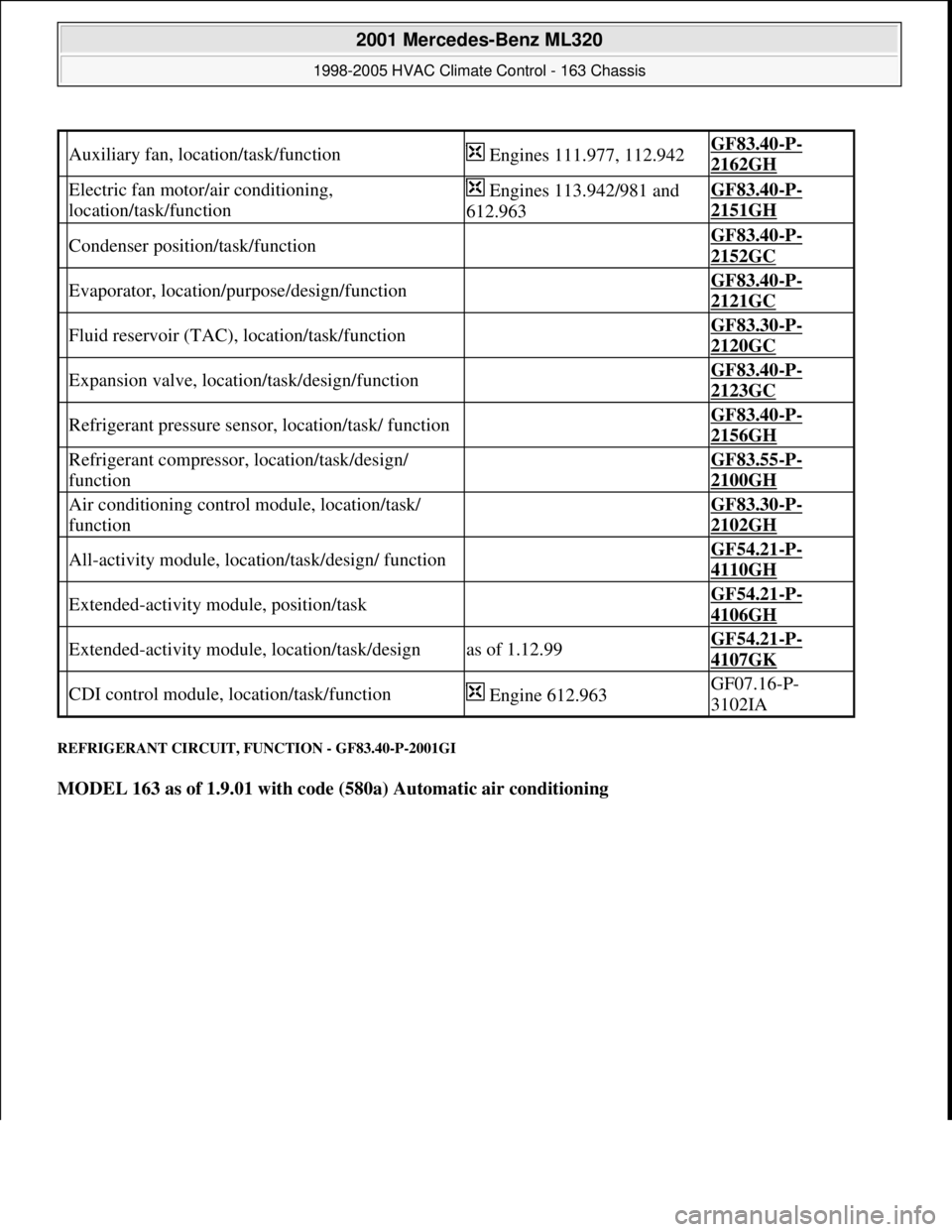
REFRIGERANT CIRCUIT, FUNCTION - GF83.40-P-2001GI
MODEL 163 as of 1.9.01 with code (580a) Automatic air conditioning
Auxiliary fan, location/task/function Engines 111.977, 112.942GF83.40-P-
2162GH
Electric fan motor/air conditioning,
location/task/function Engines 113.942/981 and
612.963GF83.40-P-
2151GH
Condenser position/task/function GF83.40-P-
2152GC
Evaporator, location/purpose/design/function GF83.40-P-
2121GC
Fluid reservoir (TAC), location/task/function GF83.30-P-
2120GC
Expansion valve, location/task/design/function GF83.40-P-
2123GC
Refrigerant pressure sensor, location/task/ function GF83.40-P-
2156GH
Refrigerant compressor, location/task/design/
function GF83.55-P-
2100GH
Air conditioning control module, location/task/
function GF83.30-P-
2102GH
All-activity module, location/task/design/ function GF54.21-P-
4110GH
Extended-activity module, position/task GF54.21-P-
4106GH
Extended-activity module, location/task/designas of 1.12.99GF54.21-P-
4107GK
CDI control module, location/task/function Engine 612.963GF07.16-P-
3102IA
2001 Mercedes-Benz ML320
1998-2005 HVAC Climate Control - 163 Chassis
me
Saturday, October 02, 2010 3:23:16 PMPage 86 © 2006 Mitchell Repair Information Company, LLC.
Page 3332 of 4133
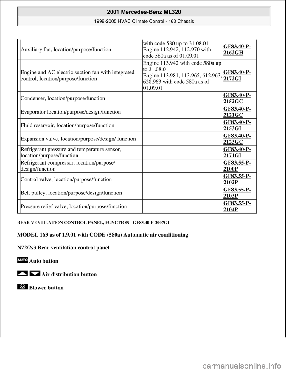
REAR VENTILATION CO NTROL PANEL, FUNCTION - GF83.40-P-2007GI
MODEL 163 as of 1.9.01 with CODE (580a) Automatic air conditioning
N72/2s3 Rear ventilation control panel
Auto button
Air distribution button
Blower button
Auxiliary fan, location/purpose/function
with code 580 up to 31.08.01
Engine 112.942, 112.970 with
code 580a as of 01.09.01GF83.40-P-
2162GH
Engine and AC electric su ction fan with integrated
control, location/purpose/function
Engine 113.942 with code 580a up
to 31.08.01
Engine 113.981, 113.965, 612.963,
628.963 with code 580a as of
01.09.01
GF83.40-P-
2172GI
Condenser, location/purpose/function GF83.40-P-
2152GC
Evaporator location/purpose/design/function GF83.40-P-
2121GC
Fluid reservoir, location/purpose/function GF83.40-P-
2153GI
Expansion valve, locati on/purpose/design/ function GF83.40-P-
2123GC
Refrigerant pressure and temperature sensor,
location/purpose/function GF83.40-P-
2171GI
Refrigerant compressor, location/purpose/
design/function GF83.55-P-
2100P
Control valve, location/purpose/function GF83.55-P-
2102P
Belt pulley, location/ purpose/design/function GF83.55-P-
2103P
Pressure relief valve, location/purpose/function GF83.55-P-
2104P
2001 Mercedes-Benz ML320
1998-2005 HVAC Climate Control - 163 Chassis
me
Saturday, October 02, 2010 3:23:16 PMPage 88 © 2006 Mitchell Repair Information Company, LLC.
Page 3341 of 4133
REST BUTTON, FUNCTION - GF83.40-P-2109-01GI
Function
Pressing the reset button ( ) on the AAC push-button control module (N22) switches on the residual engine
heat utilization system. When the engine is switched off, the residual heat heats the vehicle depending on the
temperature setting on the AAC push-button control panel (N22) and the ambient temperature in the vehicle
interior. The vehicle can be heated for approx. 30 min, with the engine switched off. The function is only
available with the ignition switched off or in position 1. If there is low voltage, the residual heat function is
automatically switched off.
The flaps are in automatic mode and the quantity of air is also automatically regulated.
The residual heat function is switched off,
if the electronic key is moved to position 2 in the starter switch,
after approx. 30 minutes,
if the battery voltage drops below 11V.
AUXILIARY FAN, FUNCTION - GF83.40-P-2115-01GH
Function
Depending on the refrigerant pressure and/or the coolant temperature the left auxiliary fan (M4m1), right
auxiliary fan (M4m2) are actuated.
The all-activity module (AAM) (N10) receives the coolant temperature from the coolant temperature sensor and
the refrigerant pressure from the refrigerant pressure sensor (B12).
The all-activity module (AAM) (N10) compares this input information with stored values and actuates the left
auxiliary fan (M4m1), right auxiliary fan (M4m2).
When the following values are indicated the left auxiliary fan (M4m1), right auxiliary fan (M4m2) are switched
on or off:
refrigerant pressure >16 bar = auxiliary fan ON
refrigerant pressure < 12 bar = auxiliary fan OFF
coolant temperature > 105°C = auxiliary fan ON
coolant temperature < 94°C = auxiliary fan OFF
AUXILIARY FAN, FUNCTION - GF83.40-P-2115-01GI
Function
Depending on the refrigerant pressure and/or the coolant temperature the left auxiliary fan (M4m1) and the right
auxiliary fan (M4m2) are actuated.
2001 Mercedes-Benz ML320
1998-2005 HVAC Climate Control - 163 Chassis
me
Saturday, October 02, 2010 3:23:16 PMPage 97 © 2006 Mitchell Repair Information Company, LLC.
Page 3342 of 4133

The all-activity module (AAM) (N10) receives the coolant temperature by the coolant temperature sensor
(B11/4) and the refrigerant pressure by the refrigerant pressure and temperature sensor (B12/2). The all-activity
module (AAM) (N10) compares this input information with stored values and actuates the left auxiliary fan
(M4m1) and the right auxiliary fan (M4m2).
When the following values are indicated the left auxiliary fan (M4m1), right auxiliary fan (M4m2) are switched
on or off:
refrigerant pressure >16 bar = auxiliary fan ON
refrigerant pressure <13 bar = auxiliary fan OFF
coolant temperature > 105°C = auxiliary fan ON
coolant temperature < 97°C = auxiliary fan OFF
AUXILIARY FAN, LOCATION - GF83.40-P-2115-02GH
The auxiliary fans are located (M4) directly in front of the condenser.
Fig. 79: Identifying Left Auxiliary Fan And Right Additional Fan
ENGINE/AIR CONDITIONING ELECTRIC FAN, FUNCTION - GF83.40-P-2118-01GH
Function
Depending on the refrigerant pressure and/or the coolant temperature the fan speed is increased infinitely.
Engines 612.963 and 628.963
The CDI control module (N3/9) receives the coolant temperature from the coolant temperature sensor and via
the all-activity module (AAM) (N10) via the CAN bus the refrigerant pressure from the refrigerant pressure
sensor (B12).
2001 Mercedes-Benz ML320
1998-2005 HVAC Climate Control - 163 Chassis
me
Saturday, October 02, 2010 3:23:16 PMPage 98 © 2006 Mitchell Repair Information Company, LLC.
Page 3349 of 4133
Fig. 85: Identifying Expansion Valve Design
REFRIGERANT PRESSURE SENSOR, FUNCTION - GF83.40-P-2126-01GH
Function
Shutting off the refrigerant compressor
The refrigerant pressure sensor (B12) sends the current value to the All Activity Module (N10). The All
Activity Module (N10) compares this input information with stored values and actuates the refrigerant
compressor.
At the following values, the refrigerant compressor is switched on or off:
refrigerant pressure > 3 bar = refrigerant compressor ON
refrigerant pressure < 2 bar = refrigerant compressor OFF
refrigerant pressure < 26 bar = refrigerant compressor ON
refrigerant pressure > 30 bar = refrigerant compressor OFF
Cut-in of the auxiliary fan (engines 111.977 and 112.942)
The pressure value received from the refrigerant pressure sensor (B12) is recorded by the All Activity Module
(N10) and compared there with a stored value.
As of 12/99, the Extended Activity Module (EAM, N10/1) assumes this task from the All Activity Module
(N10).
At the following values, the auxiliary fan (M4m1, M4m2) is switched on or off:
refrigerant pressure > 16 bar = auxiliary fan ON
refrigerant pressure <12 bar = auxiliary fan OFF
Cut-in of the electric fan for engine/AC (engines 113.942/981 and 612.963)
The pressure value received from the refrigerant pressure sensor (B12) is recorded by the All Activity Module
(N10), sent to the control module inte
grated in the electric fan for engine/AC and compared there with a stored
Expansion valve,
locationModel 168GF83.40-P-2123-
02GC
Model 163GF83.40-P-2123-
02GH
Expansion valve, taskThe expansion valve injects the liquid refrigerant into the
evaporator.
Expansion valve,
function GF83.40-P-2123-
01GC
2001 Mercedes-Benz ML320
1998-2005 HVAC Climate Control - 163 Chassis
me
Saturday, October 02, 2010 3:23:16 PMPage 105 © 2006 Mitchell Repair Information Company, LLC.
Page 3356 of 4133
REFRIGERANT PRESSURE SENSOR, LOCATION/TASK/FUNCTION - GF83.40-P-2156GH
MODEL 163 up to 31.08.01 with CODE (580) Air conditioning or Tempmatic for USA
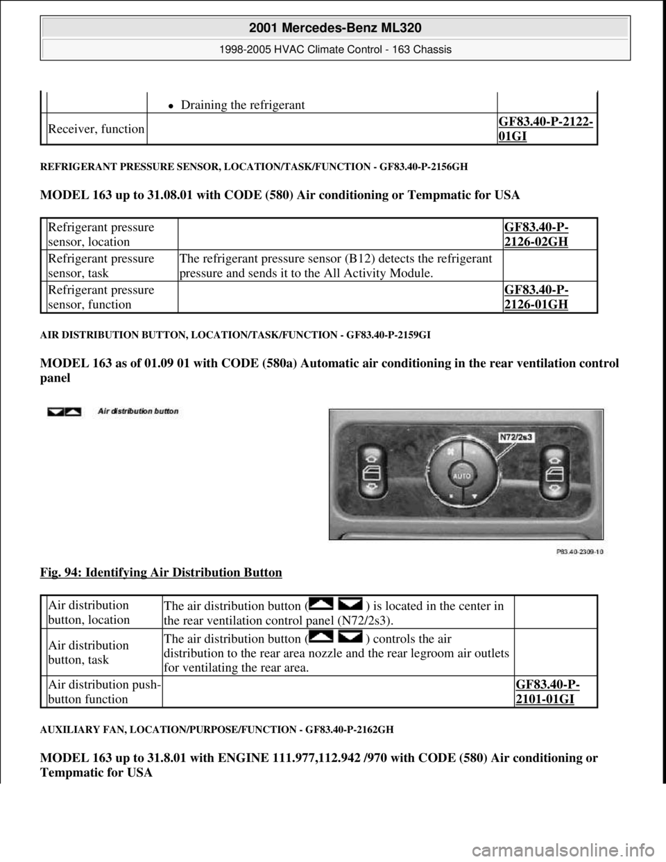
AIR DISTRIBUTION BUTTON, LOCATION/TASK/FUNCTION - GF83.40-P-2159GI
MODEL 163 as of 01.09 01 with CODE (580a) Automatic air conditioning in the rear ventilation control
panel
Fig. 94: Identifying Air Distribution Button
AUXILIARY FAN, LOCATION/PURPOSE/FUNCTION - GF83.40-P-2162GH
MODEL 163 up to 31.8.01 with ENGINE 111.977,112.942 /970 with CODE (580) Air conditioning or
Tempmatic for USA
Draining the refrigerant
Receiver, function GF83.40-P-2122-
01GI
Refrigerant pressure
sensor, location GF83.40-P-
2126-02GH
Refrigerant pressure
sensor, taskThe refrigerant pressure sensor (B12) detects the refrigerant
pressure and sends it to the All Activity Module.
Refrigerant pressure
sensor, function GF83.40-P-
2126-01GH
Air distribution
button, locationThe air distribution button ( ) is located in the center in
the rear ventilation control panel (N72/2s3).
Air distribution
button, taskThe air distribution button ( ) controls the air
distribution to the rear area nozzle and the rear legroom air outlets
for ventilating the rear area.
Air distribution push-
button function GF83.40-P-
2101-01GI
2001 Mercedes-Benz ML320
1998-2005 HVAC Climate Control - 163 Chassis
me
Saturday, October 02, 2010 3:23:16 PMPage 112 © 2006 Mitchell Repair Information Company, LLC.
Page 3357 of 4133
MODEL 163 as of 1.9.01 with ENGINE 112.942 /970 with CODE (580a) Automatic air conditioning
REFRIGERANT PRESSURE AND TEMPERATURE SENSOR, FUNCTION - GF83.40-P-2171-01GI
Detecting the refrigerant pressure
The refrigerant pressure and temperature sensor (B12/2) detects the refrigerant pressure and sends the
determined value via the CAN-BUS to the AAC push-button control module (N22). This value is compared
with a stored temperature/pressure curve.
The refrigerant pressure and temperature sensor (B12/2) operates in a pressure value range of from 0 to 35 bar.
Shutting of the refrigerant compressor
At the following values, the refrigerant compressor is switched off.
refrigerant pressure < 1.75 bar = refrigerant compressor OFF
refrigerant pressure > 30 bar = refrigerant compressor OFF
Switching on the refrigerant compressor
The refrigerant compressor is switched on at the following value
refrigerant pressure > 2.25 bar = refrigerant compressor ON
Detecting the refrigerant temperature
The refrigerant pressure and temperature sensor (B12/2) detects the temperature of the refrigerant and sends the
determined value via the CAN-BUS to the AAC push-button control module (N22). This value is compared
with a stored temperature/pressure curve and the refrigerant level is determined as a result.
With a refrigerant level that is too low, the refrigerant compressor is switched off by the AAC push-button
control module (N22) via the CAN-BUS.
The AC OFF mode is activated and can no longer be quit. Only when the error has been eliminated and the
diagnostic trouble code memory in the AAC push-button control module (N22) has been erased will the system
be operational again.
Auxiliary fan,
location GF83.40-P-2115-
02GH
Auxiliary fan,
purposeThe left auxiliary fan (M4m1) and right auxiliary fan (M4m2) serve
for cooling the coolant and the refrigerant.
Auxiliary fan,
functionup to 31.08.01GF83.40-P-2115-
01GH
as of 1.09.01GF83.40-P-2115-
01GI
2001 Mercedes-Benz ML320
1998-2005 HVAC Climate Control - 163 Chassis
me
Saturday, October 02, 2010 3:23:16 PMPage 113 © 2006 Mitchell Repair Information Company, LLC.
Page 3363 of 4133
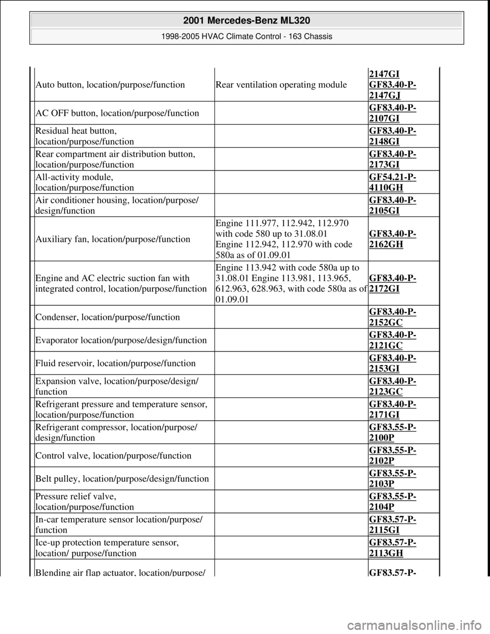
Auto button, location/purpose/functionRear ventilation operating module
2147GI
GF83.40
-P-
2147GJ
AC OFF button, location/purpose/function GF83.40-P-
2107GI
Residual heat button,
location/purpose/function GF83.40-P-
2148GI
Rear compartment air distribution button,
location/purpose/function GF83.40-P-
2173GI
All-activity module,
location/purpose/function GF54.21-P-
4110GH
Air conditioner housing, location/purpose/
design/function GF83.40-P-
2105GI
Auxiliary fan, location/purpose/function
Engine 111.977, 112.942, 112.970
with code 580 up to 31.08.01
Engine 112.942, 112.970 with code
580a as of 01.09.01
GF83.40-P-
2162GH
Engine and AC electric suction fan with
integrated control, location/purpose/function
Engine 113.942 with code 580a up to
31.08.01 Engine 113.981, 113.965,
612.963, 628.963, with code 580a as o
f
01.09.01
GF83.40-P-
2172GI
Condenser, location/purpose/function GF83.40-P-
2152GC
Evaporator location/purpose/design/function GF83.40-P-
2121GC
Fluid reservoir, location/purpose/function GF83.40-P-
2153GI
Expansion valve, location/purpose/design/
function GF83.40-P-
2123GC
Refrigerant pressure and temperature sensor,
location/purpose/function GF83.40-P-
2171GI
Refrigerant compressor, location/purpose/
design/function GF83.55-P-
2100P
Control valve, location/purpose/function GF83.55-P-
2102P
Belt pulley, location/purpose/design/function GF83.55-P-
2103P
Pressure relief valve,
location/purpose/function GF83.55-P-
2104P
In-car temperature sensor location/purpose/
function GF83.57-P-
2115GI
Ice-up protection temperature sensor,
location/ purpose/function GF83.57-P-
2113GH
Blending air flap actuator, location/purpose/ GF83.57-P-
2001 Mercedes-Benz ML320
1998-2005 HVAC Climate Control - 163 Chassis
me
Saturday, October 02, 2010 3:23:16 PMPage 119 © 2006 Mitchell Repair Information Company, LLC.