AUX MERCEDES-BENZ ML350 1997 Complete Workshop Manual
[x] Cancel search | Manufacturer: MERCEDES-BENZ, Model Year: 1997, Model line: ML350, Model: MERCEDES-BENZ ML350 1997Pages: 4133, PDF Size: 88.89 MB
Page 2506 of 4133
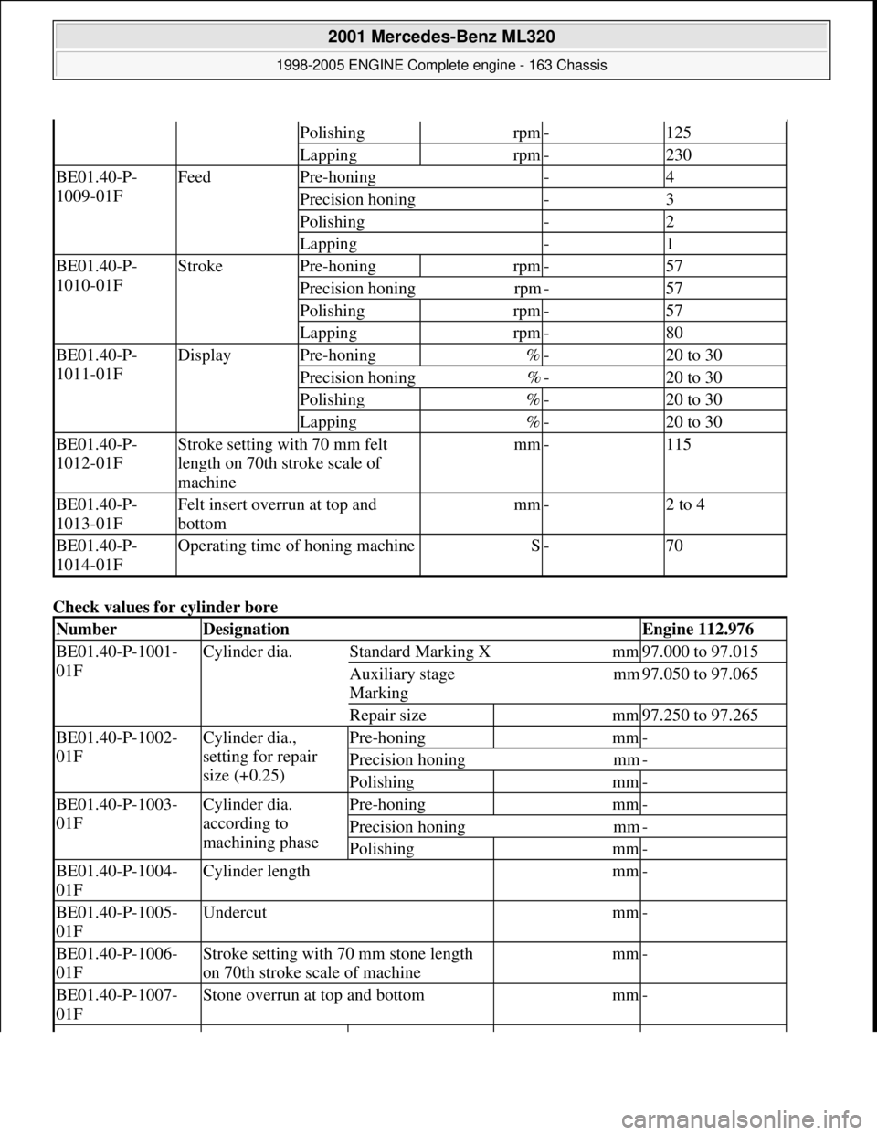
Check values for cylinder bore
Polishingrpm-125
Lappingrpm-230
BE01.40-P-
1009-01FFeedPre-honing-4
Precision honing-3
Polishing-2
Lapping-1
BE01.40-P-
1010-01FStrokePre-honingrpm-57
Precision honingrpm-57
Polishingrpm-57
Lappingrpm-80
BE01.40-P-
1011-01FDisplayPre-honing%-20 to 30
Precision honing%-20 to 30
Polishing%-20 to 30
Lapping%-20 to 30
BE01.40-P-
1012-01FStroke setting with 70 mm felt
length on 70th stroke scale of
machinemm-115
BE01.40-P-
1013-01FFelt insert overrun at top and
bottommm-2 to 4
BE01.40-P-
1014-01FOperating time of honing machineS-70
NumberDesignationEngine 112.976
BE01.40-P-1001-
01FCylinder dia.Standard Marking Xmm97.000 to 97.015
Auxiliary stage
Marking mm97.050 to 97.065
Repair sizemm97.250 to 97.265
BE01.40-P-1002-
01FCylinder dia.,
setting for repair
size (+0.25)Pre-honingmm-
Precision honingmm-
Polishingmm-
BE01.40-P-1003-
01FCylinder dia.
according to
machining phasePre-honingmm-
Precision honingmm-
Polishingmm-
BE01.40-P-1004-
01FCylinder lengthmm-
BE01.40-P-1005-
01FUndercutmm-
BE01.40-P-1006-
01FStroke setting with 70 mm stone length
on 70th stroke s cale of machinemm-
BE01.40-P-1007-
01FStone overrun at top and bottommm-
2001 Mercedes-Benz ML320
1998-2005 ENGINE Complete engine - 163 Chassis
me
Saturday, October 02, 2010 3:17:58 PMPage 150 © 2006 Mitchell Repair Information Company, LLC.
Page 2507 of 4133
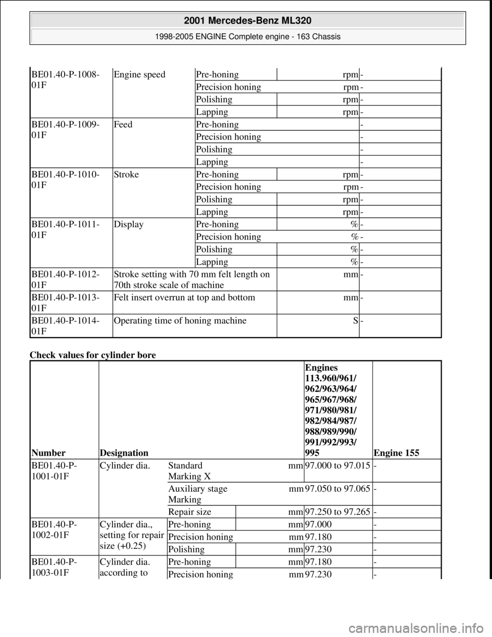
Check values for cylinder bore
BE01.40-P-1008-
01FEngine speedPre-honingrpm-
Precision honingrpm-
Polishingrpm-
Lappingrpm-
BE01.40-P-1009-
01FFeedPre-honing-
Precision honing-
Polishing-
Lapping-
BE01.40-P-1010-
01FStrokePre-honingrpm-
Precision honingrpm-
Polishingrpm-
Lappingrpm-
BE01.40-P-1011-
01FDisplayPre-honing%-
Precision honing%-
Polishing%-
Lapping%-
BE01.40-P-1012-
01FStroke setting with 70 mm felt length on
70th stroke scale of machinemm-
BE01.40-P-1013-
01FFelt insert overrun at top and bottommm-
BE01.40-P-1014-
01FOperating time of honing machineS-
NumberDesignation
Engines
113.960/961/
962/963/964/
965/967/968/
971/980/981/
982/984/987/
988/989/990/
991/992/993/
995
Engine 155
BE01.40-P-
1001-01FCylinder dia.Standard
Marking Xmm97.000 to 97.015-
Auxiliary stage
Marking mm97.050 to 97.065-
Repair sizemm97.250 to 97.265-
BE01.40-P-
1002-01FCylinder dia.,
setting for repair
size (+0.25)Pre-honingmm97.000-
Precision honingmm97.180-
Polishingmm97.230-
BE01.40-P-
1003-01FCylinder dia.
according to Pre-honingmm97.180-
Precision honingmm97.230-
2001 Mercedes-Benz ML320
1998-2005 ENGINE Complete engine - 163 Chassis
me
Saturday, October 02, 2010 3:17:58 PMPage 151 © 2006 Mitchell Repair Information Company, LLC.
Page 2541 of 4133
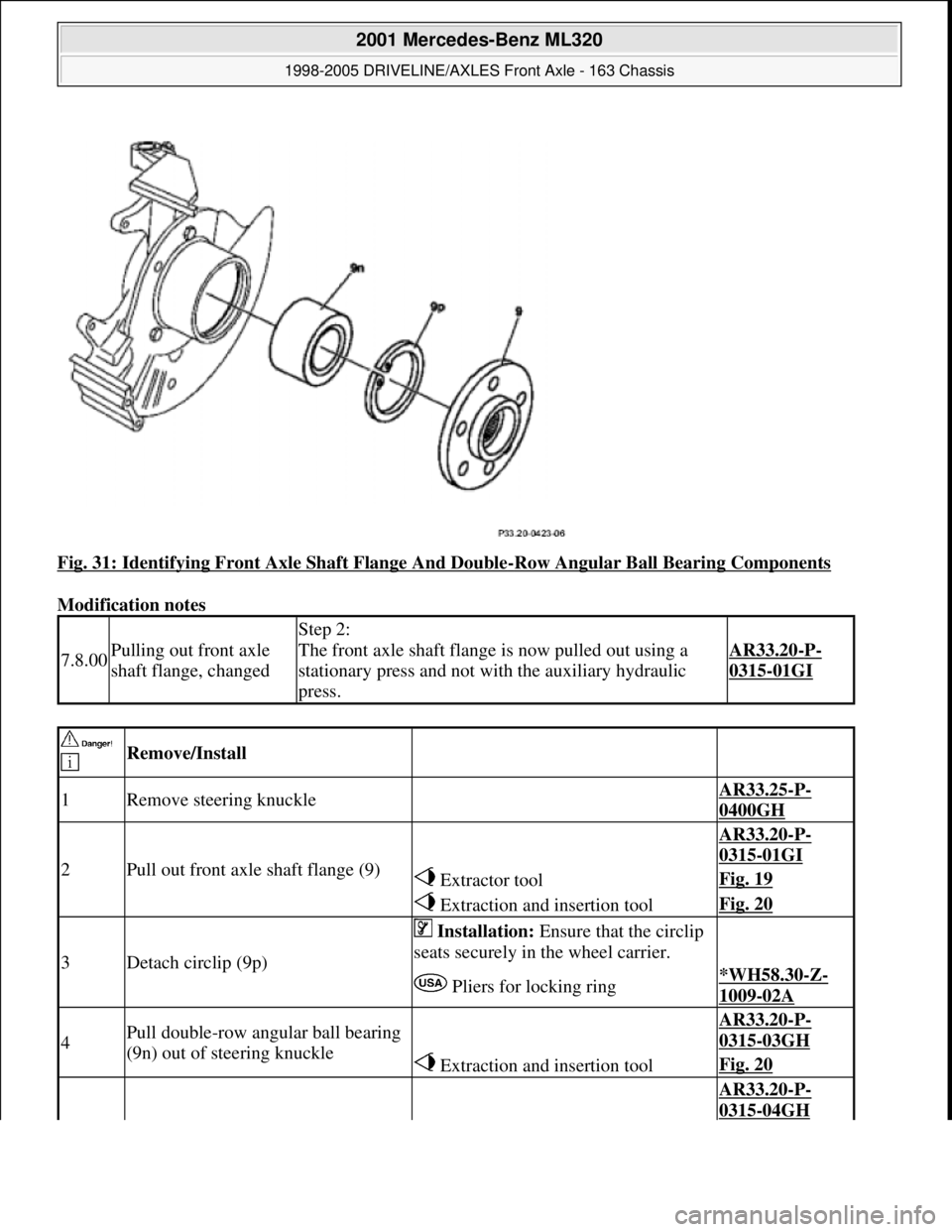
Fig. 31: Identifying Front Axle Shaft Flange And Double-Row Angular Ball Bearing Components
Modification notes
7.8.00Pulling out front axle
shaft flange, changed
Step 2:
The front axle shaft flange is now pulled out using a
stationary press and not with the auxiliary hydraulic
press.
AR33.20-P-
0315-01GI
Remove/Install
1Remove steering knuckle AR33.25-P-
0400GH
2Pull out front axle shaft flange (9)
AR33.20-P-
0315-01GI
Extractor toolFig. 19
Extraction and insertion toolFig. 20
3Detach circlip (9p)
Installation: Ensure that the circlip
seats securely in the wheel carrier.
Pliers for locking ring*WH58.30-Z-
1009-02A
4Pull double-row angular ball bearing
(9n) out of steering knuckle AR33.20-P-
0315-03GH
Extraction and insertion toolFig. 20
AR33.20-P-
0315-04GH
2001 Mercedes-Benz ML320
1998-2005 DRIVELINE/AXLES Front Axle - 163 Chassis
me
Saturday, October 02, 2010 3:38:22 PMPage 22 © 2006 Mitchell Repair Information Company, LLC.
Page 2655 of 4133
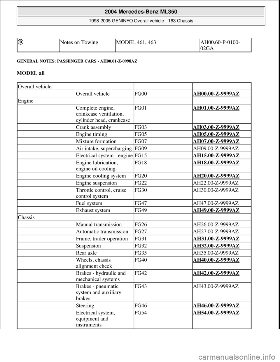
GENERAL NOTES: PASSENGER CARS - AH00.01-Z-0998AZ
MODEL all
Notes on TowingMODEL 461, 463AH00.60-P-0100-
02GA
Overall vehicle
Overall vehicleFG00AH00.00-Z-9999AZ
Engine
Complete engine,
crankcase ventilation,
cylinder head, crankcaseFG01AH01.00-Z-9999AZ
Crank assemblyFG03AH03.00-Z-9999AZ
Engine timingFG05AH05.00-Z-9999AZ
Mixture formationFG07AH07.00-Z-9999AZ
Air intake, superchargingFG09AH09.00-Z-9999AZ
Electrical system - engineFG15AH15.00-Z-9999AZ
Engine lubrication,
engine oil coolingFG18AH18.00-Z-9999AZ
Engine cooling systemFG20AH20.00-Z-9999AZ
Engine suspensionFG22AH22.00-Z-9999AZ
Throttle control, cruise
control systemFG30AH30.00-Z-9999AZ
Fuel systemFG47AH47.00-Z-9999AZ
Exhaust systemFG49AH49.00-Z-9999AZ
Chassis
Manual transmissionFG26AH26.00-Z-9999AZ
Automatic transmissionFG27AH27.00-Z-9999AZ
Frame, trailer operationFG31AH31.00-Z-9999AZ
SuspensionFG32AH32.00-Z-9999AZ
Rear axleFG35AH35.00-Z-9999AZ
Wheels, chassis
alignment checkFG40AH40.00-Z-9999AZ
Brakes - hydraulic and
mechanical systemsFG42AH42.00-Z-9999AZ
Brakes - pneumatic
system and auxiliary
brakesFG43AH43.00-Z-9999AZ
SteeringFG46AH46.00-Z-9999AZ
Electrical system,
equipment and
instrumentsFG54AH54.00-Z-9999AZ
2004 Mercedes-Benz ML350
1998-2005 GENINFO Overall vehicle - 163 Chassis
me
Saturday, October 02, 2010 3:47:44 PMPage 10 © 2006 Mitchell Repair Information Company, LLC.
Page 2690 of 4133
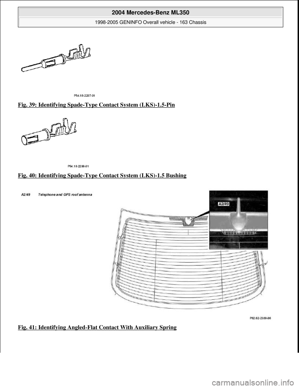
Fig. 39: Identifying Spade-Type Contact System (LKS)-1.5-Pin
Fig. 40: Identifying Spade
-Type Contact System (LKS)-1.5 Bushing
Fig. 41: Identifying Angled
-Flat Contact With Auxiliary Spring
2004 Mercedes-Benz ML350
1998-2005 GENINFO Overall vehicle - 163 Chassis
me
Saturday, October 02, 2010 3:47:44 PMPage 45 © 2006 Mitchell Repair Information Company, LLC.
Page 3158 of 4133
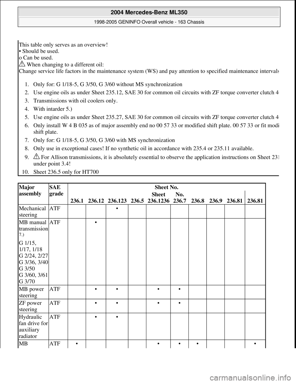
This table only serves as an overview!
• Should be used.
o Can be used.
When changing to a different oil:
Change service life factors in the maintenance system (WS) and pay attention to specified maintenance interval
s
1. Only for: G 1/18-5, G 3/50, G 3/60 without MS synchronization
2. Use engine oils as under Sheet 235.12, SAE 30 for common oil circuits with ZF torque converter clutch 4
0
3. Transmissions with oil coolers only.
4. With intarder 5.)
5. Use engine oils as under Sheet 235.27, SAE 30 for common oil circuits with ZF torque converter clutch 4
0
6. Only install W 4 B 035 as of major assembly end no 00 57 33 or modified shift plate. 00 57 33 or fit modi
shift plate.
7. Only for: G 1/18-5, G 3/50, G 3/60 with MS synchronization
8. Only use in exceptional cases! If no synthetic oil in accordance with 235.4 or 235.11 available.
9. For Allison transmissions, it is absolutely essential to observe the application instructions on Sheet 23
1
under point 3.4!
10. Sheet 236.5 only for HT700
Major
assemblySAE
gradeSheet No.
236.1236.12236.123236.5
Sheet
236.1236No.
236.7
236.8236.9236.81236.81
Mechanical
steeringATF •
MB manual
transmission
7.)
G 1/15,
1/17, 1/18
G 2/24, 2/27
G 3/36, 3/40
G 3/50
G 3/60, 3/61
G 3/70
ATF •
MB power
steeringATF •• ••
ZF power
steeringATF •• ••
Hydraulic
fan drive for
auxiliary
radiatorATF ••
MB ATF• ••• •
2004 Mercedes-Benz ML350
1998-2005 GENINFO Overall vehicle - 163 Chassis
me
Saturday, October 02, 2010 3:47:56 PMPage 513 © 2006 Mitchell Repair Information Company, LLC.
Page 3194 of 4133
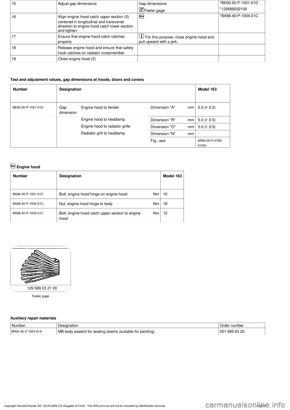
15
Adjust gap dimensions
Gap dimensions
*BE60.00-P-1001-01D
Feeler gage
*129589032100
16
Align engine hood catch upper section (5)
centered in longitudinal and transverse
direction to engine hood catch lower section
and tighten
*BA88.40-P-1004-01C
17
Ensure that engine hood catch catches
properly
For this purpose, close engine hood and
pull upward with a jerk.
18
Release engine hood and ensure that safety
hook catches on radiator crossmember
19
Close engine hood (2)
Test and adjustment values, gap dimensions at hoods, doors and covers
Number
Designation
Model 163
BE60.00-P-1001-01D
Gap
dimension
Engine hood to fender
Dimension "A"
mm
5.0 (
F
0.5)
Engine hood to headlamp
Dimension "R"
mm
5.0 (
F
0.5)
Engine hood to radiator grille
Dimension "O"
mm
5.0 (
F
0.5)
Radiator grill to headlamp
Dimension "N"
mm
-
Fig., see
AR60.00-P-0700-
01GH
Engine hood
Number
Designation
Model 163
BA88.40-P-1001-01C
Bolt, engine hood hinge on engine hood
Nm
10
BA88.40-P-1002-01C
Nut, engine hood hinge to body
Nm
18
BA88.40-P-1004-01C
Bolt, engine hood catch upper section to engine
hood
Nm
12
129 589 03 21 00
Feeler gage
Auxiliary repair materials
Number
Designation
Order number
BR00.45-Z-1004-01A
MB body sealant for sealing seams (suitable for painting)
001 989 63 20
Copyright DaimlerChrysler AG 09.05.2006 CD-Ausgabe G/10/04 . This WIS print-out will not be recorde
d by Modification services.
Page 2
Page 3196 of 4133
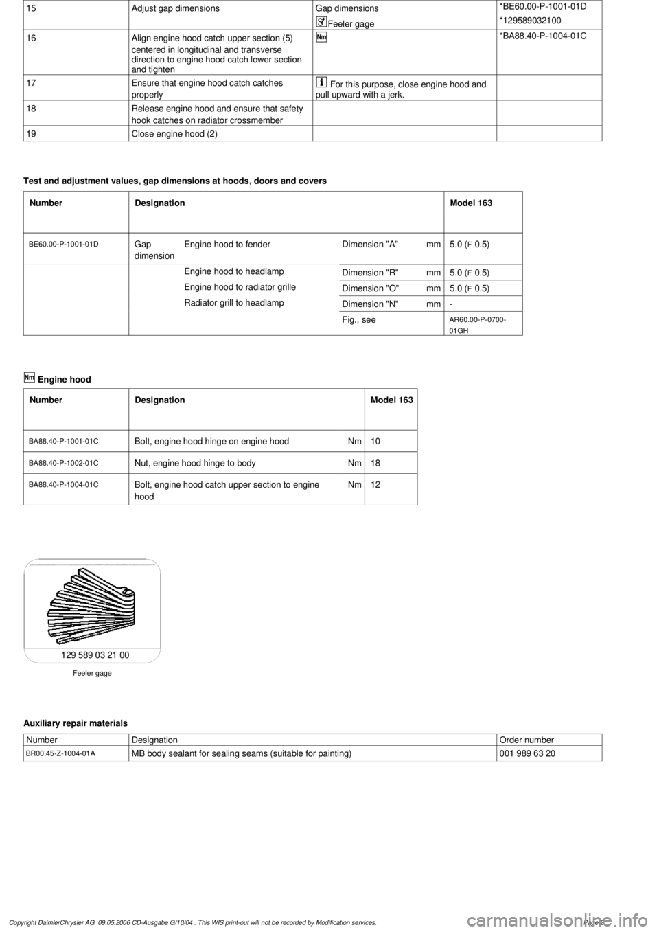
15
Adjust gap dimensions
Gap dimensions
*BE60.00-P-1001-01D
Feeler gage
*129589032100
16
Align engine hood catch upper section (5)
centered in longitudinal and transverse
direction to engine hood catch lower section
and tighten
*BA88.40-P-1004-01C
17
Ensure that engine hood catch catches
properly
For this purpose, close engine hood and
pull upward with a jerk.
18
Release engine hood and ensure that safety
hook catches on radiator crossmember
19
Close engine hood (2)
Test and adjustment values, gap dimensions at hoods, doors and covers
Number
Designation
Model 163
BE60.00-P-1001-01D
Gap
dimension
Engine hood to fender
Dimension "A"
mm
5.0 (
F
0.5)
Engine hood to headlamp
Dimension "R"
mm
5.0 (
F
0.5)
Engine hood to radiator grille
Dimension "O"
mm
5.0 (
F
0.5)
Radiator grill to headlamp
Dimension "N"
mm
-
Fig., see
AR60.00-P-0700-
01GH
Engine hood
Number
Designation
Model 163
BA88.40-P-1001-01C
Bolt, engine hood hinge on engine hood
Nm
10
BA88.40-P-1002-01C
Nut, engine hood hinge to body
Nm
18
BA88.40-P-1004-01C
Bolt, engine hood catch upper section to engine
hood
Nm
12
129 589 03 21 00
Feeler gage
Auxiliary repair materials
Number
Designation
Order number
BR00.45-Z-1004-01A
MB body sealant for sealing seams (suitable for painting)
001 989 63 20
Copyright DaimlerChrysler AG 09.05.2006 CD-Ausgabe G/10/04 . This WIS print-out will not be recorde
d by Modification services.
Page 2
Page 3225 of 4133
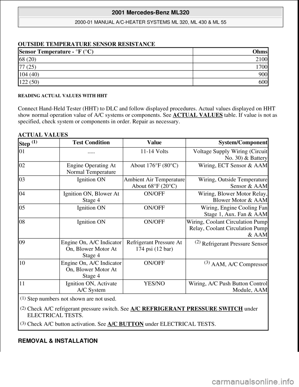
OUTSIDE TEMPERATURE SENSOR RESISTANCE
READING ACTUAL VALUES WITH HHT
Connect Hand-Held Tester (HHT) to DLC and follow displayed procedures. Actual values displayed on HHT
show normal operation value of A/C systems or components. See ACTUAL VALUES
table. If value is not as
specified, check system or components in order. Repair as necessary.
ACTUAL VALUES
REMOVAL & INSTALLATION
Sensor Temperature - °F (°C)Ohms
68 (20)2100
77 (25)1700
104 (40)900
122 (50)600
Step (1) Test ConditionValueSystem/Component
01.....11-14 VoltsVoltage Supply Wiring (Circuit
No. 30) & Battery
02Engine Operating At
Normal TemperatureAbout 176°F (80°C)Wiring, ECT Sensor & AAM
03Ignition ONAmbient Air Temperature
About 68°F (20°C)Wiring, Outside Temperature
Sensor & AAM
04Ignition ON, Blower At
Stage 4ON/OFFWiring, Blower Motor Relay,
Blower Motor & AAM
05Ignition ONON/OFFWiring, Engine Cooling Fan
Stage 1, Aux. Fan & AAM
08Ignition ONON/OFFWiring, Coolant Circulation Pump
Relay, Coolant Circulation Pump
& AAM
09Engine On, A/C Indicator
On, Blower Motor At
Stage 4Refrigerant Pressure At
174 psi (12 bar)(2) Refrigerant Pressure Sensor
10Engine On, A/C Indicator
On, Blower Motor At
Stage 4ON/OFF(3) AAM, A/C Compressor
11Ignition ON, Activate
A/C SystemYES/NOWiring, A/C Push Button Control
Module, AAM
(1)Step numbers not shown are not used.
(2)Check A/C refrigerant pressure switch. See A/C REFRIGERANT PRESSURE SWITCH under
ELECTRICAL TESTS.
(3)Check A/C button activation. See A/C BUTTON under ELECTRICAL TESTS.
2001 Mercedes-Benz ML320
2000-01 MANUAL A/C-HEATER SYSTEMS ML 320, ML 430 & ML 55
me
Saturday, October 02, 2010 3:25:10 PMPage 14 © 2006 Mitchell Repair Information Company, LLC.
Page 3318 of 4133
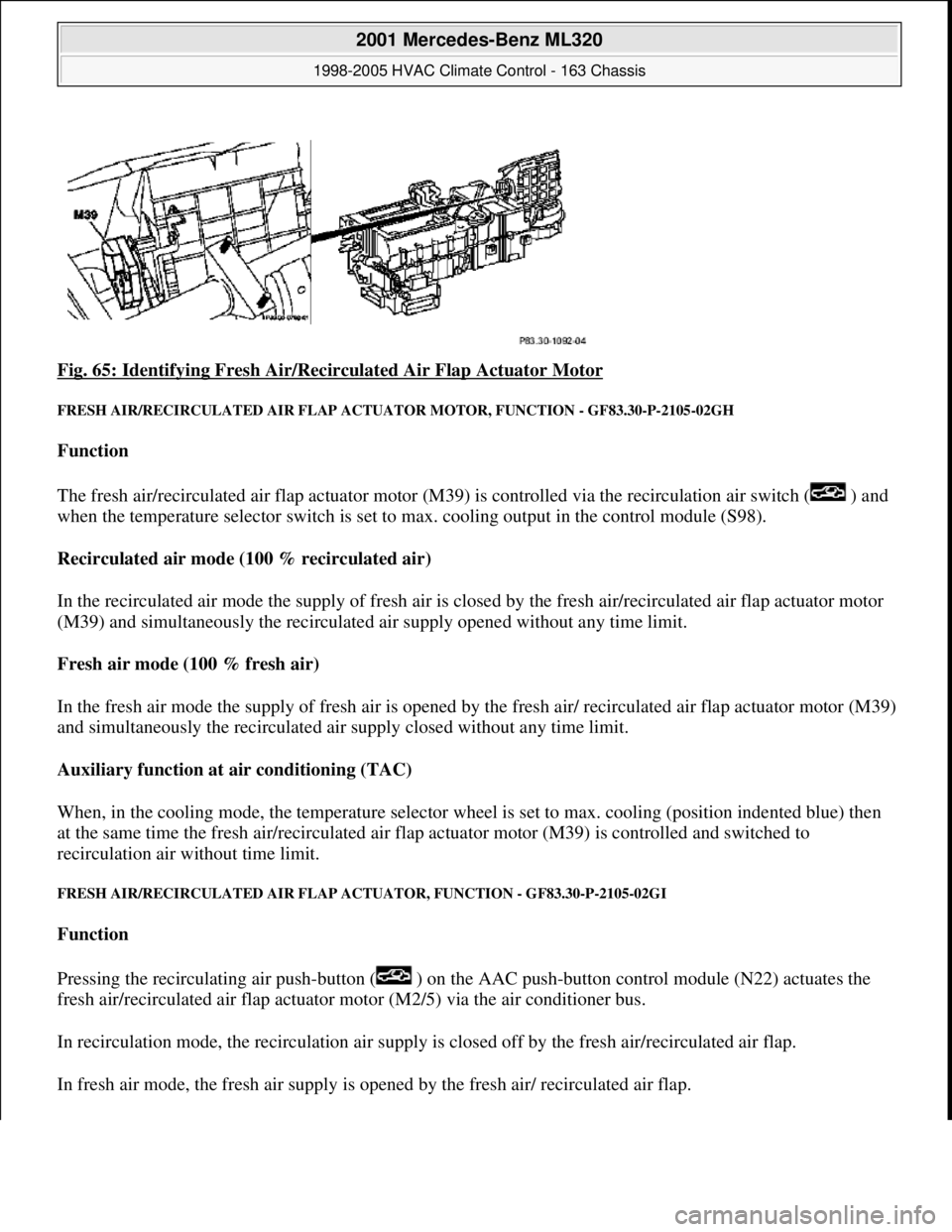
Fig. 65: Identifying Fresh Air/Recirc ulated Air Flap Actuator Motor
FRESH AIR/RECIRCULATED AIR FLAP ACTUATOR MOTO R, FUNCTION - GF83.30-P-2105-02GH
Function
The fresh air/recirculated air flap actuator motor (M39) is controlled via the recirculation air switch ( ) and
when the temperature selector switch is set to max. cooling output in the control module (S98).
Recirculated air mode (100 % recirculated air)
In the recirculated air mode the supply of fresh air is closed by the fresh air/recirculated air flap actuator motor
(M39) and simultaneously the recirculated air supply opened without any time limit.
Fresh air mode (100 % fresh air)
In the fresh air mode the supply of fresh air is opened by th e fresh air/ recirculated air flap actuator motor (M39)
and simultaneously the recirculated air supply closed without any time limit.
Auxiliary function at air conditioning (TAC)
When, in the cooling mode, the temperat ure selector wheel is set to max. cooling (position indented blue) then
at the same time the fres h air/recirculated air flap actuator moto r (M39) is controlled and switched to
recirculation air wi thout time limit.
FRESH AIR/RECIRCUL ATED AIR FLAP ACTUATOR, FU NCTION - GF83.30-P-2105-02GI
Function
Pressing the recirculating air push- button ( ) on the AAC push-button control module (N22) actuates the
fresh air/recirculated air flap actuator motor (M2/5) via the air conditioner bus.
In recirculation mode, the recircul ation air supply is closed off by th e fresh air/recirculated air flap.
In fresh air mode, the fresh air supply is ope ned by the fresh air/ recirculated air flap.
2001 Mercedes-Benz ML320
1998-2005 HVAC Climate Control - 163 Chassis
me
Saturday, October 02, 2010 3:23:15 PMPage 74 © 2006 Mitchell Repair Information Company, LLC.