coolant level MERCEDES-BENZ ML430 1997 Complete Workshop Manual
[x] Cancel search | Manufacturer: MERCEDES-BENZ, Model Year: 1997, Model line: ML430, Model: MERCEDES-BENZ ML430 1997Pages: 4133, PDF Size: 88.89 MB
Page 2584 of 4133
8
Disconnect coolant feed hose (3) to fuel cooler
Raise fuel cooler.
Hose clamp pliers (length 210 mm;
adjustment range 80 mm)
*WH58.30-Z-1026-02A
9
Install in the reverse order
Danger!
Risk of accident
as vehicle may start off by
itself with the engine running.
Risk of injury
as working around the engine during start-up
or while running may result in contusions and
burns
Secure vehicle to prevent it from moving off
by itself.
Wear closed and tight-fitting work clothes.
Do not grasp hot or rotating parts.
AS00.00-Z-0005-01A
10
Pour in coolant
*BF20.00-P-1001-02E
Switch heater to maximum and warm up
engine at moderate revs. Top up coolant
constantly at coolant expansion reservoir.
Close coolant expansion reservoir once
coolant temperature is 60-70 °C.
Note on coolant level
Models 124, 129, 140, 168, 170, 202, 208,
210, 220, 463
AH20.00-P-1142-01A
11
Inspect cooling system for leaks
AR20.00-P-1010HA
12
Run engine and inspect fuel system for leaks
Crankcase ventilation, cylinder head cover
Number
Designation
Engine
612.963
BA01.20-P-1002-01A
Screw of trim panel of cylinder head cover
to cylinder head cover
NM
10
BA01.20-P-1003-01A
Screw attaching cover panel to charge air
distribution pipe
NM
10
Cooling system
Number
Designation
Engine
612.963
BF20.00-P-1001-02E
Cooling system
Total capacity
Liter
Y
11,0
Capacity of anticorrosion/
antifreeze agent down to -37 °C
Liter
Y
5,5
Capacity of anticorrosion/
antifreeze agent down to -45 °C
Liter
Y
6,25
Specifications for Service
Products
SheetBB00.40-P-0310-01A
SheetBB00.40-P-0325-02A
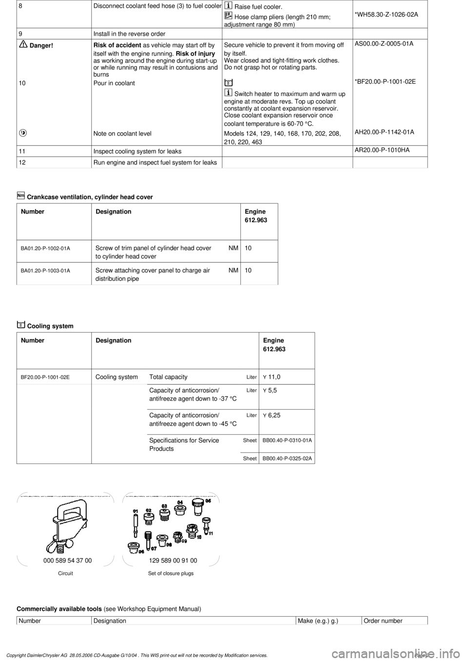
129 589 00 91 00
Set of closure plugs
Circuit
000 589 54 37 00
Commercially available tools
(see Workshop Equipment Manual)
Number
Designation
Make (e.g.) g.)
Order number
Copyright DaimlerChrysler AG 28.05.2006 CD-Ausgabe G/10/04 . This WIS print-out will not be recorde
d by Modification services.
Page 2
Page 2842 of 4133
Fig. 318: Identifying Active Service System (ASSYST) Display
ACTIVE SERVICE SYSTEM (ASSYST) INFLUENCING PARAMETERS - GF00.20-P-0003-05A
The values of various influencing parameters are required by ASSYST for calculating the demand-based service
interval, and these are included in the calculation of the service interval as weighting factors . There are two
versions within ASSYST, the difference being in the oil level sensors fitted:
The familiar oil level indicator switch (S43) is fitted to engines (104, 111, 119, 120, 602.982, 604, 605,
606). In view of the fact that this is a switch, it is only possible to detect if the oil level drops below the
minimum level.
The oil sensor (oil level/temperature/quality, B40) is used on more recent engines (e.g. 112, 113, 166,
611, 668). This sensor consists of 2 capacitor systems with the engine oil as an insulator. If the water
content of the oil or the oil level changes, there is a change in the capacitance of the "capacitor".
The capacitance is thus a measure for the oil level.
In addition, the oil sensor (oil level/temperature/quality, B40) contains a temperature sensor which
detects the temperature of the engine oil.
All the signals are processed in the electronics integrated in the sensor to form a PWM (pulse width
modulated) signal, and passed to the engine control module (N3).
In addition to the weighting factors, which depend on reallife driving conditions, quality factors are also used
for calculating the demand-based service interval (remaining distance and remaining time).
Survey of ASSYST influencing parameters
Weighting factors (dependant on reallife driving conditions):
Load torque
Engine speed
Oil level
Engine oil temperature
Oil correction factor (is used as comparative value for determining oil level)
Coolant temperature
These data are supplied by the injection system control module (N3) to the service microprocessor over
the CAN.
The data relating to oil level, engine oil temperature and oil correction factor are supplied by the oil
sensor (oil level/temperature/quality, B40) through the injection system control module (N3), and are
therefore only available on engines fitted with this sensor.
Quality factors (these are factory-set to base values and can be changed with the HHT, if operating
conditions of the vehicle so necessitate; they influence the start distance):
2004 Mercedes-Benz ML350
1998-2005 GENINFO Overall vehicle - 163 Chassis
me
Saturday, October 02, 2010 3:47:47 PMPage 197 © 2006 Mitchell Repair Information Company, LLC.
Page 2845 of 4133
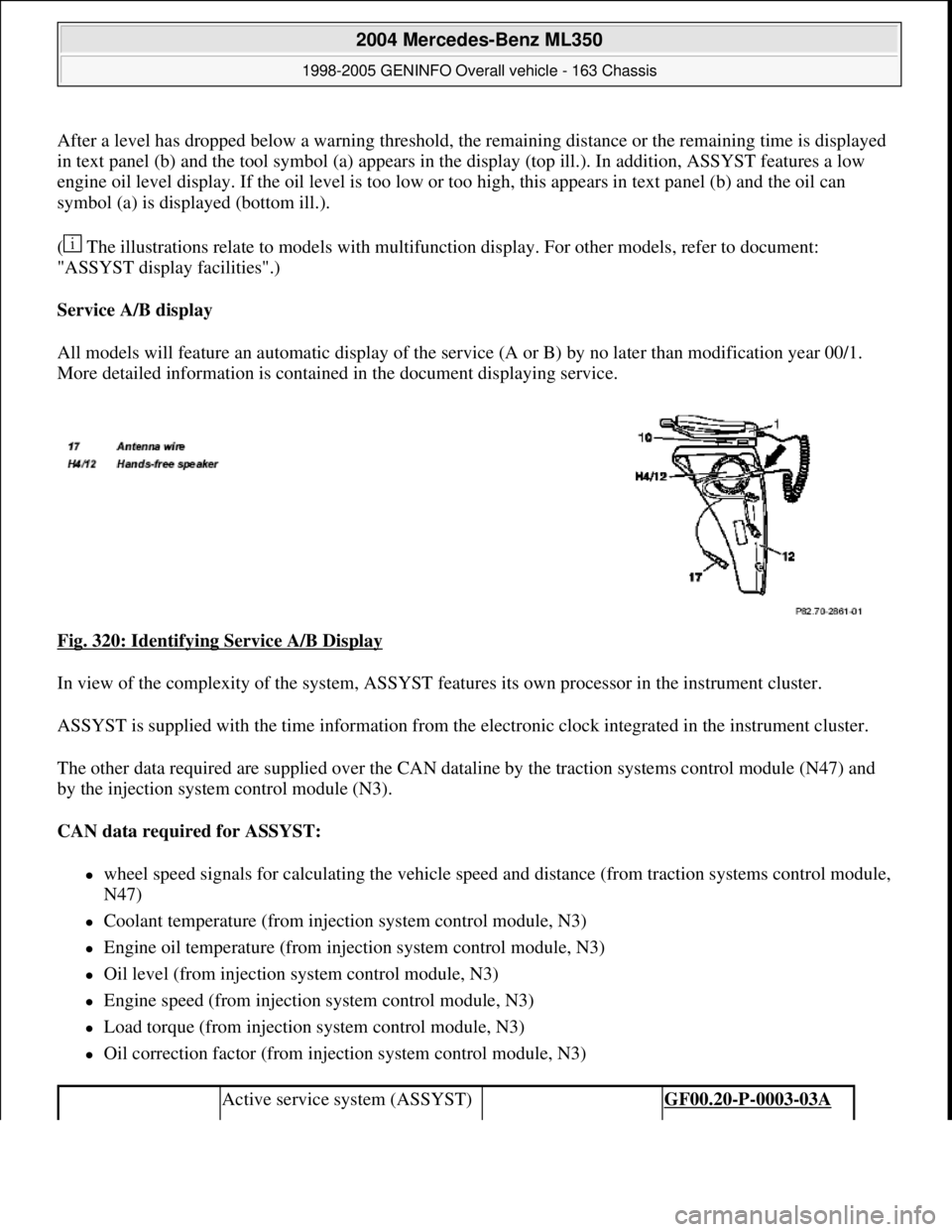
After a level has dropped below a warning threshold, the remaining distance or the remaining time is displayed
in text panel (b) and the tool symbol (a) appears in the display (top ill.). In addition, ASSYST features a low
engine oil level display. If the oil level is too low or too high, this appears in text panel (b) and the oil can
symbol (a) is displayed (bottom ill.).
( The illustrations relate to models with multifunction display. For other models, refer to document:
"ASSYST display facilities".)
Service A/B display
All models will feature an automatic display of the service (A or B) by no later than modification year 00/1.
More detailed information is contained in the document displaying service.
Fig. 320: Identifying Service A/B Display
In view of the complexity of the system, ASSYST features its own processor in the instrument cluster.
ASSYST is supplied with the time information from the electronic clock integrated in the instrument cluster.
The other data required are supplied over the CAN dataline by the traction systems control module (N47) and
by the injection system control module (N3).
CAN data required for ASSYST:
wheel speed signals for calculating the vehicle speed and distance (from traction systems control module,
N47)
Coolant temperature (from injection system control module, N3)
Engine oil temperature (from injection system control module, N3)
Oil level (from injection system control module, N3)
Engine speed (from injection system control module, N3)
Load torque (from injection system control module, N3)
Oil correction factor (from injection system control module, N3)
Active service system (ASSYST) GF00.20-P-0003-03A
2004 Mercedes-Benz ML350
1998-2005 GENINFO Overall vehicle - 163 Chassis
me
Saturday, October 02, 2010 3:47:47 PMPage 200 © 2006 Mitchell Repair Information Company, LLC.
Page 3051 of 4133
RENDER NEW VEHICLES, WHICH WERE IMMOBILIZED OPERATIONAL - AP00.70-P-1001ZZ
MODEL 129, 140, 163, 168, 170, 202, 203, 208, 209, 210, 211, 215, 220, 230, 240
MODEL 461.302 /332 /342 /345
MODEL
463.200 /204 /206 /207 /208 /209 /220 /221 /224/225 /227 /228 /230 /231 /232 /233 /240 /241 /243 /244 /245 /2
4
servicerecommend that the
vehicle fuel tank is
completely filled. Then
allow gasoline engines to
run warm for 2-3 minutes.
Notes on paintwork,
decorative and detachable
components AH98.00-P-9019-01Z
if necessary, corrosion
protection after painting
(Section D) AP98.00-P-0641A
1Perform delivery
inspection
2Check battery AR54.10-P-1129-01A
3
+Vent stationary heater and
top up coolantModel 163, 168, 170, 202,
203, 208, 209, 210, 211,
215, 220, 230, 240, 461,
463
Models 129, 140 with
stationary heater, code 228ra83001291165x
4Check fluid level of
engine cooling system,
correct if necessary and
check corrosion protection
as well as antifreeze and
correct if necessaryModel 129, 140, 163, 168,
170, 202, 203, 208, 209,
210, 211, 215, 220, 230,
240
Model 463 with engine
112, 113AP20.00-P-2010GA
Models 461, 463 with
engines 102, 103, 104,
117, 602, 603, 606, 612,
628AP20.00-P-2010G
Risk of accident caused
by vehicle starting off by
itself when engine is
running. Risk of injury
caused by contusions and
burns during starting Secure vehicle to prevent
it from moving. Wear
closed and snug-fitting
work clothes. Do not grasp
hot or rotating parts.AS00.00-Z-0005-01A
2004 Mercedes-Benz ML350
1998-2005 GENINFO Overall vehicle - 163 Chassis
me
Saturday, October 02, 2010 3:47:52 PMPage 406 © 2006 Mitchell Repair Information Company, LLC.
Page 3166 of 4133
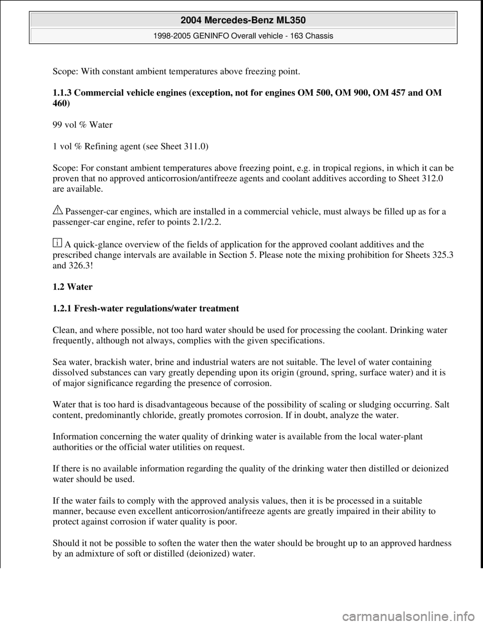
Scope: With constant ambient temperatures above freezing point.
1.1.3 Commercial vehicle engines (exception, not for engines OM 500, OM 900, OM 457 and OM
460)
99 vol % Water
1 vol % Refining agent (see Sheet 311.0)
Scope: For constant ambient temperatures above freezing point, e.g. in tropical regions, in which it can be
proven that no approved anticorrosion/antifreeze agents and coolant additives according to Sheet 312.0
are available.
Passenger-car engines, which are installed in a commercial vehicle, must always be filled up as for a
passenger-car engine, refer to points 2.1/2.2.
A quick-glance overview of the fields of application for the approved coolant additives and the
prescribed change intervals are available in Section 5. Please note the mixing prohibition for Sheets 325.3
and 326.3!
1.2 Water
1.2.1 Fresh-water regulations/water treatment
Clean, and where possible, not too hard water should be used for processing the coolant. Drinking water
frequently, although not always, complies with the given specifications.
Sea water, brackish water, brine and industrial waters are not suitable. The level of water containing
dissolved substances can vary greatly depending upon its origin (ground, spring, surface water) and it is
of major significance regarding the presence of corrosion.
Water that is too hard is disadvantageous because of the possibility of scaling or sludging occurring. Salt
content, predominantly chloride, greatly promotes corrosion. If in doubt, analyze the water.
Information concerning the water quality of drinking water is available from the local water-plant
authorities or the official water utilities on request.
If there is no available information regarding the quality of the drinking water then distilled or deionized
water should be used.
If the water fails to comply with the approved analysis values, then it is be processed in a suitable
manner, because even excellent anticorrosion/antifreeze agents are greatly impaired in their ability to
protect against corrosion if water quality is poor.
Should it not be possible to soften the water then the water should be brought up to an approved hardness
by an admixture of soft or distilled (deionized) water.
2004 Mercedes-Benz ML350
1998-2005 GENINFO Overall vehicle - 163 Chassis
me
Saturday, October 02, 2010 3:47:57 PMPage 521 © 2006 Mitchell Repair Information Company, LLC.
Page 3167 of 4133
If the chloride or total ionic content of the water is too high, then the level can be reduced through the
admixture of demineralized, in other words, ion-exchanged or distilled water.
Particular treatment processes will need to be used (desalination and demineralization or subprocesses)
depending upon the contaminants present in the water. Information on how to conduct water treatment is
available from water plants or water utilities as well as several companies and engineering consultants
who are experienced in this area.
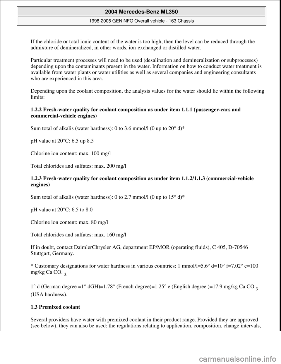
Depending upon the coolant composition, the analysis values for the water should lie within the following
limits:
1.2.2 Fresh-water quality for coolant composition as under item 1.1.1 (passenger-cars and
commercial-vehicle engines)
Sum total of alkalis (water hardness): 0 to 3.6 mmol/l (0 up to 20° d)*
pH value at 20°C: 6.5 up 8.5
Chlorine ion content: max. 100 mg/l
Total chlorides and sulfates: max. 200 mg/l
1.2.3 Fresh-water quality for coolant composition as under item 1.1.2/1.1.3 (commercial-vehicle
engines)
Sum total of alkalis (water hardness): 0 to 2.7 mmol/l (0 up to 15° d)*
pH value at 20°C: 6.5 to 8.0
Chlorine ion content: max. 80 mg/l
Total chlorides and sulfates: max. 160 mg/l
If in doubt, contact DaimlerChrysler AG, department EP/MOR (operating fluids), C 405, D-70546
Stuttgart, Germany.
* Customary designations for water hardness in various countries: 1 mmol/l=5.6° d=10° f=7.02° e=100
mg/kg Ca CO.
3.
1° d (German degree =1° dGH)=1.78° (French degree)=1.25° e (English degree )=17.9 mg/kg Ca CO
3
(USA hardness).
1.3 Premixed coolant
Several providers have water with premixed coolant in their product range. Provided they are approved
(see below), the
y can also be used; the regulations relating to application, composition, change intervals,
2004 Mercedes-Benz ML350
1998-2005 GENINFO Overall vehicle - 163 Chassis
me
Saturday, October 02, 2010 3:47:57 PMPage 522 © 2006 Mitchell Repair Information Company, LLC.
Page 3168 of 4133
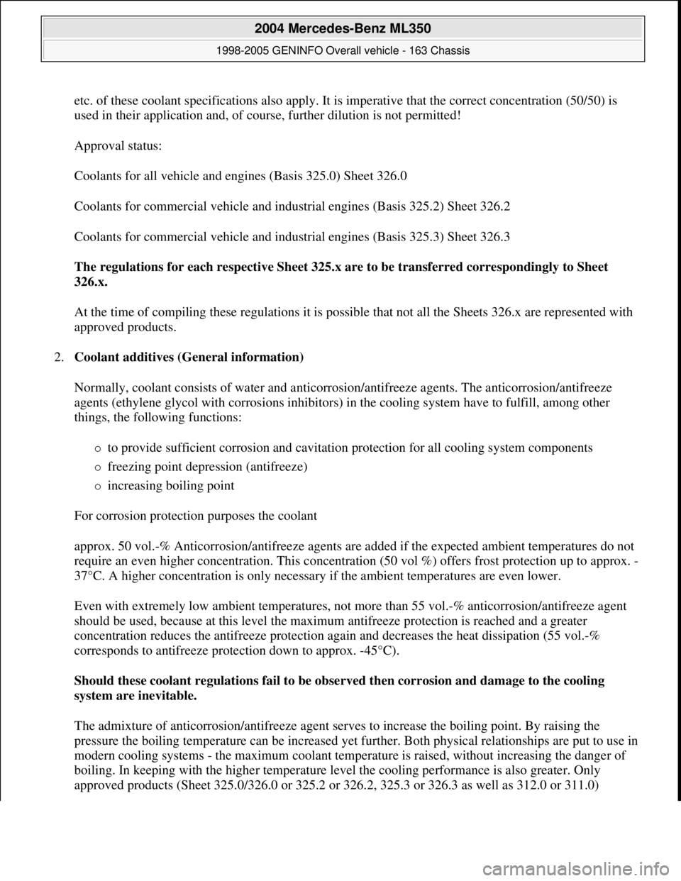
etc. of these coolant specifications also apply. It is imperative that the correct concentration (50/50) is
used in their application and, of course, further dilution is not permitted!
Approval status:
Coolants for all vehicle and engines (Basis 325.0) Sheet 326.0
Coolants for commercial vehicle and industrial engines (Basis 325.2) Sheet 326.2
Coolants for commercial vehicle and industrial engines (Basis 325.3) Sheet 326.3
The regulations for each respective Sheet 325.x are to be transferred correspondingly to Sheet
326.x.
At the time of compiling these regulations it is possible that not all the Sheets 326.x are represented with
approved products.
2.Coolant additives (General information)
Normally, coolant consists of water and anticorrosion/antifreeze agents. The anticorrosion/antifreeze
agents (ethylene glycol with corrosions inhibitors) in the cooling system have to fulfill, among other
things, the following functions:
to provide sufficient corrosion and cavitation protection for all cooling system components
freezing point depression (antifreeze)
increasing boiling point
For corrosion protection purposes the coolant
approx. 50 vol.-% Anticorrosion/antifreeze agents are added if the expected ambient temperatures do not
require an even higher concentration. This concentration (50 vol %) offers frost protection up to approx. -
37°C. A higher concentration is only necessary if the ambient temperatures are even lower.
Even with extremely low ambient temperatures, not more than 55 vol.-% anticorrosion/antifreeze agent
should be used, because at this level the maximum antifreeze protection is reached and a greater
concentration reduces the antifreeze protection again and decreases the heat dissipation (55 vol.-%
corresponds to antifreeze protection down to approx. -45°C).
Should these coolant regulations fail to be observed then corrosion and damage to the cooling
system are inevitable.
The admixture of anticorrosion/antifreeze agent serves to increase the boiling point. By raising the
pressure the boiling temperature can be increased yet further. Both physical relationships are put to use in
modern cooling systems - the maximum coolant temperature is raised, without increasing the danger of
boiling. In keeping with the higher temperature level the cooling performance is also greater. Only
approved products (Sheet 325.0/326.0 or 325.2 or 326.2, 325.3 or 326.3 as well as 312.0 or 311.0)
2004 Mercedes-Benz ML350
1998-2005 GENINFO Overall vehicle - 163 Chassis
me
Saturday, October 02, 2010 3:47:57 PMPage 523 © 2006 Mitchell Repair Information Company, LLC.
Page 3170 of 4133
Overview Section 5). However, it should always be remembered that anticorrosion/antifreeze
a
gents or coolants conforming to Sheet 325.3 and 326.3 must not be mixed with those conforming to
Sheet 325.0 or 326.0 or 325.2 and 326.2.
2.3 Coolant additives for commercial-vehicle en
gines without antifreeze specifications (refer to item
1.1.2) (not: BR 600, BR 100 and BR 200)
In those application cases where no antifreeze is necessary, coolant for commercial-vehicle engines as
under item 1.1.2 can be mixed to suit. It is impossible to cite generalized mixing proportions because the
application concentrations of products included in Sheet 312.0 may be different. If the tolerances exceed
or fall below those given in Sheet 312.0, then appropriate adjustments must be made. The coolant's
boiling point is only insignificantly increased by these additives. The starting-off water underlies the
more stringent regulations as under point 1.2.3. The usage period for this coolant is shorter than usual (see
position 3). If it is necessary to refill, the same product must be used and at the same concentration level.
The blending of different products is not permitted as stated in Sheet 312.0.
2.4 Coolant regulations for commercial vehicle engines (exception, not for engines OM 500, OM
900, OM 457 and OM 460)
In the event that neither an approved anticorrosion/antifreeze agent is available, nor a coolant additive in
accordance with sheet 312.0 and if temperatures do not drop below freezing then it is possible in this
exceptional case to use a coolant refining agent to 1 vol % if it is approved in sheet 311.0 (soluble
corrosion protection oil). This will not raise the boiling point. The starting-off water itself underlies the
more stringent regulations as under point 1.2.3.
The period of usage for this coolant, which may only be used in exceptional circumstances, is shorter than
usual (refer to position 3).
Water that is too hard may impair the emulsion resistance, with the result that the emulsion
breaks down (oil separation) and the engine's water jackets are contaminated.
2.4.1 Applying water refining mixture
When carrying out a new filling (initial filling or filling after a cleansing operation) an emulsion of 1.0-
1.5 vol % should be used. When refilling, an emulsion of 0.5-1.0 vol % should be used. Concentrations
that are too high (>1.5 vol %) do not improve the corrosion protection capability and may exert a negative
influence on seals and hoses.
3.Monitoring coolant operation
It is very important to monitor the coolant constantly if the engine is to run trouble free.
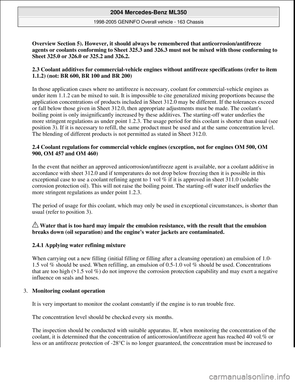
The concentration level should be checked every six months.
The inspection should be conducted with suitable apparatus. If, when monitoring the concentration of the
coolant, it is determined that the concentration of anticorrosion/antifreeze agent has reached 40 vol.% or
less or an antifreeze protection of -28°C is no lon
ger guaranteed, the concentration must be increased to
2004 Mercedes-Benz ML350
1998-2005 GENINFO Overall vehicle - 163 Chassis
me
Saturday, October 02, 2010 3:47:57 PMPage 525 © 2006 Mitchell Repair Information Company, LLC.
Page 3171 of 4133
the regulation filling of 50 vol.% (-37°C). When topping up (after coolant loss), an anticorrosion/
antifreeze agent content in the coolant of at least 50 vol. % (antifreeze protection down to -37°C) must be
ensured, or the concentration regulations according to point 2.3/2.4.1 must be observed. In closing an
example is given in Overview Section 5.
Non observance a observance of these regulations or the use of non-approved products will
result in serious damage.
The corrosion inhibitors diminish during operation and lose their protective capability. Coolant that is too
old, and has lost its important inhibitors and anti-aging additives, becomes strongly corrosive. The
coolant additives as under Sheets 311.0 and 312.0 will also age. This causes a deterioration in the level of
protection capability, and with regard to coolant refining agents this will also cause the emulsion to break
down.
For this reason it is important to replace the coolant, in order to ensure that its corrosion protection
capability is retained. If necessary the cooling system should be thoroughly cleansed before refilling with
the new coolant. A sufficient level of heat dissipation will only be given if the cooler surfaces are clean.
The maximum permissible period of usage for coolant is cited in Overview Section 5.
The use of approved operatin
g fluids, which naturally include the anticorrosion/antifreeze agents, is
a well-known constituent of the warranty conditions.
4.Disposal of coolants
The coolants are biologically-degradable material.
All statutory regulations or waste water regulations in each individual country with regard to the disposal
of used coolant must be observed.
It is recommended to have the possibilities available for disposing of materials explained by the local
responsible water authorities.
Currently in Germany methods are being compiled for the purification of used coolant. The separate
collection of all used operating fluids is highly recommended.
However, as a consequence of the complex tasks asked of a modern coolant, it is on no account advisable
to use an improperly "recycled" coolant, which has only undergone a mechanical pre-purification process
5.Overview
Which coolant additive, what change interval for which engines?
Passenger cars engines
Sheet No.Engine seriesChange interval
years/km
M100/M200OM600
2004 Mercedes-Benz ML350
1998-2005 GENINFO Overall vehicle - 163 Chassis
me
Saturday, October 02, 2010 3:47:57 PMPage 526 © 2006 Mitchell Repair Information Company, LLC.
Page 3288 of 4133
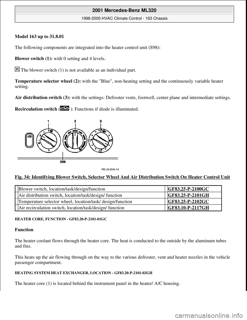
Model 163 up to 31.8.01
The following components are integrated into the heater control unit (S98):
Blower switch (1): with 0 setting and 4 levels.
The blower switch (1) is not available as an individual part.
Temperature selector wheel (2): with the "Blue", non-heating setting and the continuously variable heater
setting.
Air distribution switch (3): with the settings: Defroster vents, footwe ll, center plane and intermediate settings.
Recirculation switch ( ): Functions if diode is illuminated.
Fig. 34: Identifying Blower Switch, Selector Wheel And Air Distribution Switch On Heater Control Unit
HEATER CORE, FUNCTI ON - GF83.20-P-2101-01GC
Function
The heater coolant flows through the heater core. The he at is conducted to the outside by the aluminum tubes
and fins.
This heats up the air flowing through on the way to the vari ous defroster, vent and heater nozzles in the vehicle
passenger compartment.
HEATING SYSTEM HEAT EXCHANGE R, LOCATION - GF83.20-P-2101-02GH
The heater core (1) is located behind the instrument panel in the heater/ A/C housing.
Blower switch, location/task/design/function GF83.25-P-2100GC
Air distribution switch, locat ion/task/design/ function GF83.25-P-2101GH
Temperature selector wheel, location/task/ design/function GF83.25-P-2102GC
Air recirculation switch, loca tion/task/design/ function GF83.10-P-2117GH
2001 Mercedes-Benz ML320
1998-2005 HVAC Climate Control - 163 Chassis
me
Saturday, October 02, 2010 3:23:15 PMPage 44 © 2006 Mitchell Repair Information Company, LLC.