coolant level MERCEDES-BENZ ML430 1997 Complete Manual PDF
[x] Cancel search | Manufacturer: MERCEDES-BENZ, Model Year: 1997, Model line: ML430, Model: MERCEDES-BENZ ML430 1997Pages: 4133, PDF Size: 88.89 MB
Page 3357 of 4133
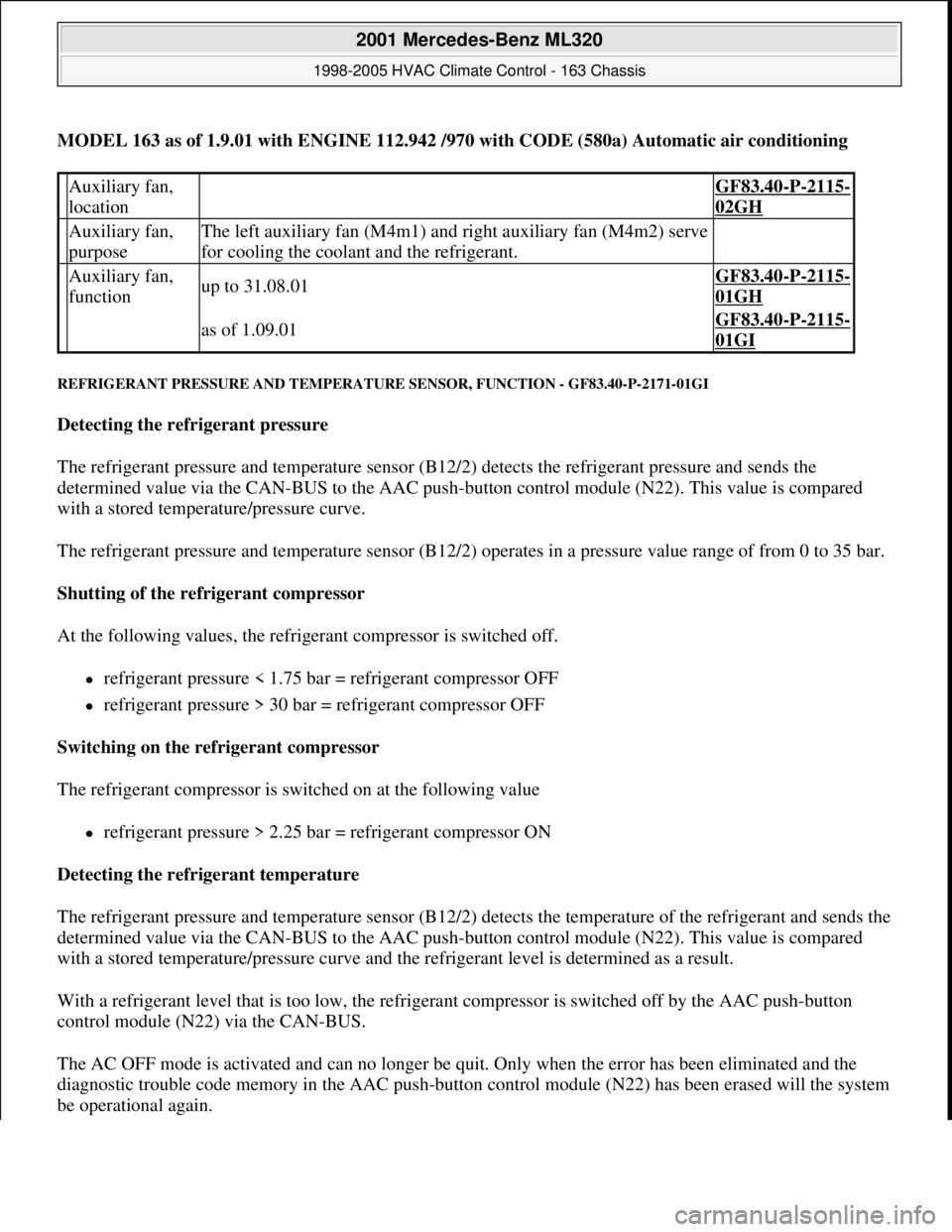
MODEL 163 as of 1.9.01 with ENGINE 112.942 /970 with CODE (580a) Automatic air conditioning
REFRIGERANT PRESSURE AND TEMPERATURE SENSOR, FUNCTION - GF83.40-P-2171-01GI
Detecting the refrigerant pressure
The refrigerant pressure and temperature sensor (B12/2) detects the refrigerant pressure and sends the
determined value via the CAN-BUS to the AAC push-button control module (N22). This value is compared
with a stored temperature/pressure curve.
The refrigerant pressure and temperature sensor (B12/2) operates in a pressure value range of from 0 to 35 bar.
Shutting of the refrigerant compressor
At the following values, the refrigerant compressor is switched off.
refrigerant pressure < 1.75 bar = refrigerant compressor OFF
refrigerant pressure > 30 bar = refrigerant compressor OFF
Switching on the refrigerant compressor
The refrigerant compressor is switched on at the following value
refrigerant pressure > 2.25 bar = refrigerant compressor ON
Detecting the refrigerant temperature
The refrigerant pressure and temperature sensor (B12/2) detects the temperature of the refrigerant and sends the
determined value via the CAN-BUS to the AAC push-button control module (N22). This value is compared
with a stored temperature/pressure curve and the refrigerant level is determined as a result.
With a refrigerant level that is too low, the refrigerant compressor is switched off by the AAC push-button
control module (N22) via the CAN-BUS.
The AC OFF mode is activated and can no longer be quit. Only when the error has been eliminated and the
diagnostic trouble code memory in the AAC push-button control module (N22) has been erased will the system
be operational again.
Auxiliary fan,
location GF83.40-P-2115-
02GH
Auxiliary fan,
purposeThe left auxiliary fan (M4m1) and right auxiliary fan (M4m2) serve
for cooling the coolant and the refrigerant.
Auxiliary fan,
functionup to 31.08.01GF83.40-P-2115-
01GH
as of 1.09.01GF83.40-P-2115-
01GI
2001 Mercedes-Benz ML320
1998-2005 HVAC Climate Control - 163 Chassis
me
Saturday, October 02, 2010 3:23:16 PMPage 113 © 2006 Mitchell Repair Information Company, LLC.
Page 3381 of 4133
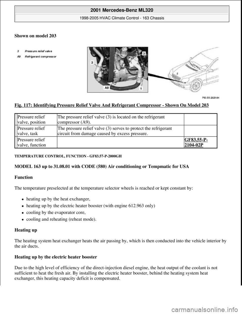
Shown on model 203
Fig. 117: Identifying Pressure Relief Valve And Refrigerant Compressor
- Shown On Model 203
TEMPERATURE CONTROL, FUNCTION - GF83.57-P-2000GH
MODEL 163 up to 31.08.01 with CODE (580) Air conditioning or Tempmatic for USA
Function
The temperature preselected at the temperature selector wheels is reached or kept constant by:
heating up by the heat exchanger,
heating up by the electric heater booster (with engine 612.963 only)
cooling by the evaporator core,
cooling and reheating (reheat mode).
Heating up
The heating system heat exchanger heats the air passing by, which is then conducted into the vehicle interior by
the air ducts.
Heating up by the electric heater booster
Due to the high level of efficiency of the direct-injection diesel engine, the heat output of the coolant is not
sufficient to heat the fresh air. By installing the electric heater booster, behind the heating system heat
exchanger, this heating capacity deficit is compensated.
Pressure relief
valve, positionThe pressure relief valve (3) is located on the refrigerant
compressor (A9).
Pressure relief
valve, taskThe pressure relief valve (3) serves to protect the refrigerant
circuit from damage caused by excess pressure.
Pressure relief
valve, function GF83.55-P-
2104-02P
2001 Mercedes-Benz ML320
1998-2005 HVAC Climate Control - 163 Chassis
me
Saturday, October 02, 2010 3:23:17 PMPage 137 © 2006 Mitchell Repair Information Company, LLC.
Page 3412 of 4133
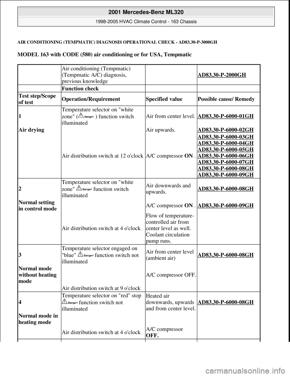
AIR CONDITIONING (TEMPMATIC) DIAGNOSIS OPERATIONAL CHECK - AD83.30-P-3000GH
MODEL 163 with CODE (580) air conditioning or for USA, Tempmatic
Air conditioning (Tempmatic)
(Tempmatic A/C) diagnosis,
previous knowledge
AD83.30-P-2000GH
Function check
Test step/Scope
of test Operation/Requirement Specified value Possible cause/ Remedy
1
Temperature selector on "white
zone" ( ) function switch
illuminated
Air from center level.AD83.30-P-6000-01GH
Air drying Air upwards.AD83.30-P-6000-02GH
Air distribution switch at 12 o'clockA/C compressor ON .
AD83.30-P-6000-03GH
AD83.30
-P-6000-04GH
AD83.30
-P-6000-05GH
AD83.30
-P-6000-06GH
AD83.30
-P-6000-07GH
AD83.30
-P-6000-08GH
AD83.30
-P-6000-09GH
2
Temperature selector on "white
zone" function switch
illuminatedAir downwards and
upwards.AD83.30-P-6000-08GH
Normal setting
in control mode A/C compressor ON .AD83.30-P-6000-09GH
Air distribution switch at 4 o'clock
Flow of temperature-
controlled air from
center level as well.
Coolant circulation
pump runs.
3
Temperature selector engaged on
"blue" function switch not
illuminatedAir from center level
(ambient air)AD83.30-P-6000-08GH
Normal mode
without heating
mode
A/C compressor OFF.
Air distribution switch at 9 o'clock
4
Temperature selector on "red" stop
function switch not
illuminatedHeated air
downwards, upwards
and from center level.
AD83.30-P-6000-08GH
Normal mode in
heating mode
Air distribution switch at 4 o'clockA/C compressor
OFF.
2001 Mercedes-Benz ML320
1998-2005 HVAC Climate Control - 163 Chassis
me
Saturday, October 02, 2010 3:23:17 PMPage 168 © 2006 Mitchell Repair Information Company, LLC.
Page 3421 of 4133
Remove/install air outlet
temperature sensorMODEL 163...AR83.30-P-
8087GJ
Remove, install in-car
temperature sensor for aspirator
blower (M9)MODELS 163.113/136/154/172/174 as of 1.9.99 up to
31.8.01AR83.30-P-
8100GH
Remove/install switch
unit/automatic air conditioning
control moduleMODEL 163.113/154 /174 #A as of 289565, 163.113 #X
as of 754620, 163.128 /157 /175AR83.40-P-
6500GH
Remove and install sun sensorMODEL 163...AR83.40-P-
6720GH
Remove/install summer/winter
operation switchMODEL 163, 168, 170, 202, 208 ...AR83.70-P-
0001A
Removing, installing stationary
heater antennaMODEL 163.### 1# Retrofitted stationary heater with
Telestart T60AR83.70-P-
0002B
Remove/install stationary heater
antennaMODEL 163.### 1# Retrofitted stationary heater with
Telestart T70AR83.70-P-
0002BA
Remove/install Telestart
receiverMODEL 163, 168, 170, 202, 208, 210 ...AR83.70-P-
0003BA
Removing and installing
telestart receiverMODEL 163.### 1# Retrofitted telestart T60AR83.70-P-
0003H
Checking Telestart remote
controlMODEL 163, 168, 170, 202, 208, 210 Telestart T60AR83.70-P-
0005A
Check Telestart transmitterMODEL 163, 168, 170, 202, 203, 208, 209,
210,211,220,463...AR83.70-P-
0005IA
Check emission level, adjust if
necessaryMODEL 163, 168, 170, 202, 208, 210 ...AR83.70-P-
1177H
Remove/install heater unitMODELS 163.136/154/157/172/174/175 1# Retrofitted
Thermo Top C stationary heaterAR83.70-P-
5302I
Remove/install heaterMODEL 163.113 1# Retrofitted Thermo Top C stationary
heaterAR83.70-P-
5302IA
Remove/install heaterMODEL 163.128 Retrofitted Thermo Top C stationary
heaterAR83.70-P-
5302IB
Remove/install combustion air
blower unitMODEL 163, 168, 170, 202, 208, 210 ...AR83.70-P-
5555G
Removing and installing fuel
metering pumpMODEL 163.### 1# up to 31.12.99 Retrofitted Thermo
Top C stationary heaterAR83.70-P-
5652G
Remove/install coolant
circulation pumpMODEL 163.### (except 163.128) 1# Retrofitted
Thermo Top C stationary heaterAR83.70-P-
5700E
Remove/install burner insertMODEL 163, 168, 170, 202, 208, 210 ...AR83.70-P-
5772G
Remove/install burner insert
with glow pinMODEL 129, 163, 168, 170, 202, 203, 209, 210, 211,
215, 219, 220, 230, 240 ...AR83.70-P-
5773A
Remove/install timerMODEL 163, 168, 170, 202, 208 ...AR83.70-P-
5892D
2001 Mercedes-Benz ML320
1998-2005 HVAC Climate Control - 163 Chassis
me
Saturday, October 02, 2010 3:23:17 PMPage 177 © 2006 Mitchell Repair Information Company, LLC.
Page 3478 of 4133
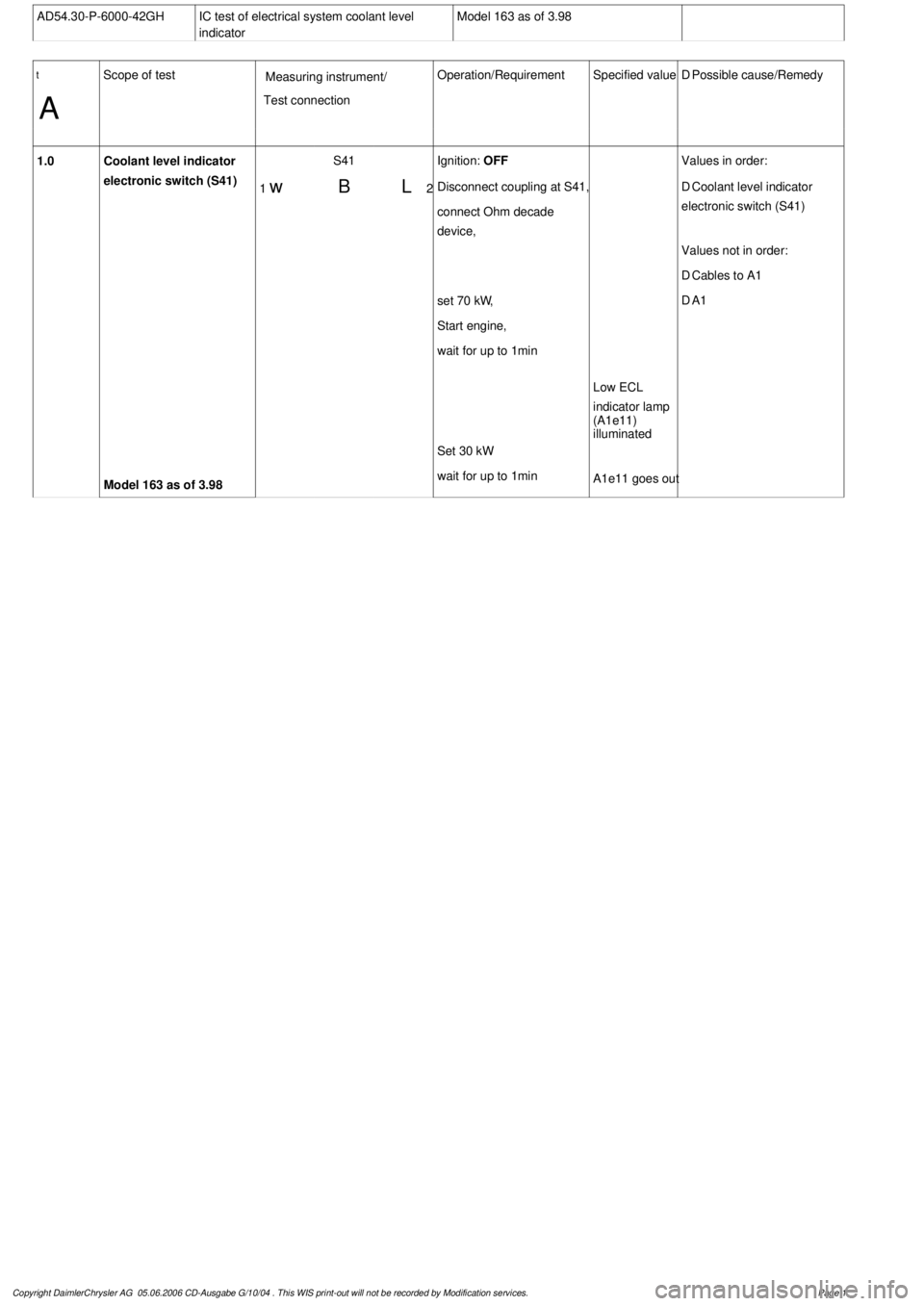
AD54.30-P-6000-42GH
IC test of electrical system coolant level
indicator
Model 163 as of 3.98
t
A
Scope of test
Measuring instrument/
Test connection
Operation/Requirement
Specified value
D
Possible cause/Remedy
1.0
Coolant level indicator
electronic switch (S41)
Model 163 as of 3.98
1
w
S41
BL
2
Ignition:
OFF
Disconnect coupling at S41,
connect Ohm decade
device,
set 70 k
W,
Start engine,
wait for up to 1min
Set 30 k
W
wait for up to 1min
Low ECL
indicator lamp
(A1e11)
illuminated
A1e11 goes out
Values in order:
D
Coolant level indicator
electronic switch (S41)
Values not in order:
D
Cables to A1
D
A1
Copyright DaimlerChrysler AG 05.06.2006 CD-Ausgabe G/10/04 . This WIS print-out will not be recorde
d by Modification services.
Page 1
Page 3480 of 4133
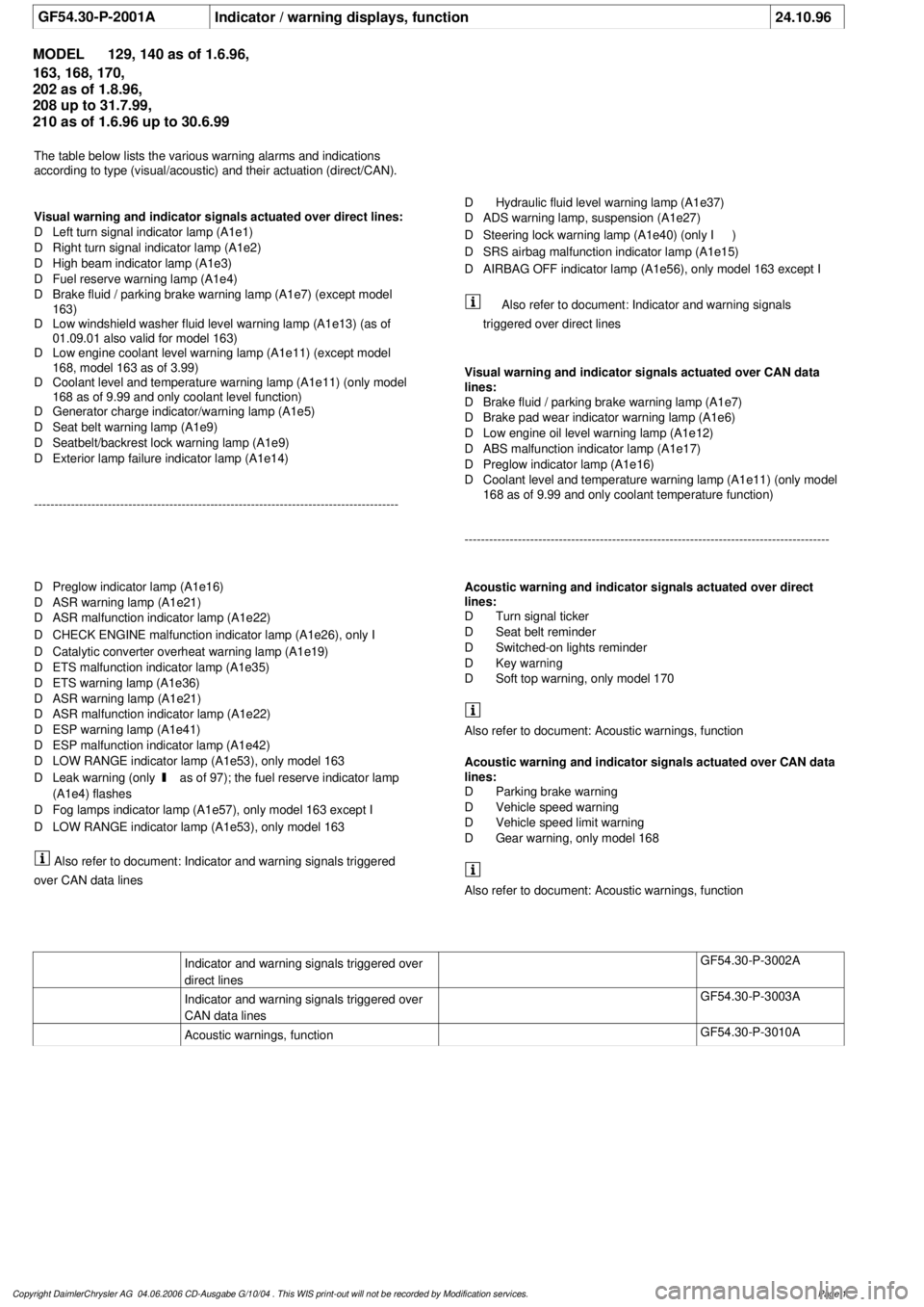
GF54.30-P-2001A
Indicator / warning displays, function
24.10.96
MODEL
129, 140 as of 1.6.96,
163, 168, 170,
202 as of 1.8.96,
208 up to 31.7.99,
210 as of 1.6.96 up to 30.6.99
The table below lists the various warning alarms and indications
according to type (visual/acoustic) and their actuation (direct/CAN).
Visual warning and indicator signals actuated over direct lines:
D
Left turn signal indicator lamp (A1e1)
D
Right turn signal indicator lamp (A1e2)
D
High beam indicator lamp (A1e3)
D
Fuel reserve warning lamp (A1e4)
D
Brake fluid / parking brake warning lamp (A1e7) (except model
163)
D
Low windshield washer fluid level warning lamp (A1e13) (as of
01.09.01 also valid for model 163)
D
Low engine coolant level warning lamp (A1e11) (except model
168, model 163 as of 3.99)
D
Coolant level and temperature warning lamp (A1e11) (only model
168 as of 9.99 and only coolant level function)
D
Generator charge indicator/warning lamp (A1e5)
D
Seat belt warning lamp (A1e9)
D
Seatbelt/backrest lock warning lamp (A1e9)
D
Exterior lamp failure indicator lamp (A1e14)
-----------------------------------------------------------------------------------------
D
Hydraulic fluid level warning lamp (A1e37)
D
ADS warning lamp, suspension (A1e27)
D
Steering lock warning lamp (A1e40) (only
I
)
D
SRS airbag malfunction indicator lamp (A1e15)
D
AIRBAG OFF indicator lamp (A1e56), only model 163 except
I
Also refer to document: Indicator and warning signals triggered
over CAN data lines
Acoustic warning and indicator signals actuated over direct
lines:
D
Turn signal ticker
D
Seat belt reminder
D
Switched-on lights reminder
D
Key warning
D
Soft top warning, only model 170
Also refer to document: Acoustic warnings, function
Acoustic warning and indicator signals actuated over CAN data
lines:
D
Parking brake warning
D
Vehicle speed warning
D
Vehicle speed limit warning
D
Gear warning, only model 168
Also refer to document: Acoustic warnings, function
Indicator and warning signals triggered over
direct lines
GF54.30-P-3002A
Indicator and warning signals triggered over
CAN data lines
GF54.30-P-3003A
Acoustic warnings, function
GF54.30-P-3010A
Copyright DaimlerChrysler AG 04.06.2006 CD-Ausgabe G/10/04 . This WIS print-out will not be recorde
d by Modification services.
Page 1
Page 3481 of 4133
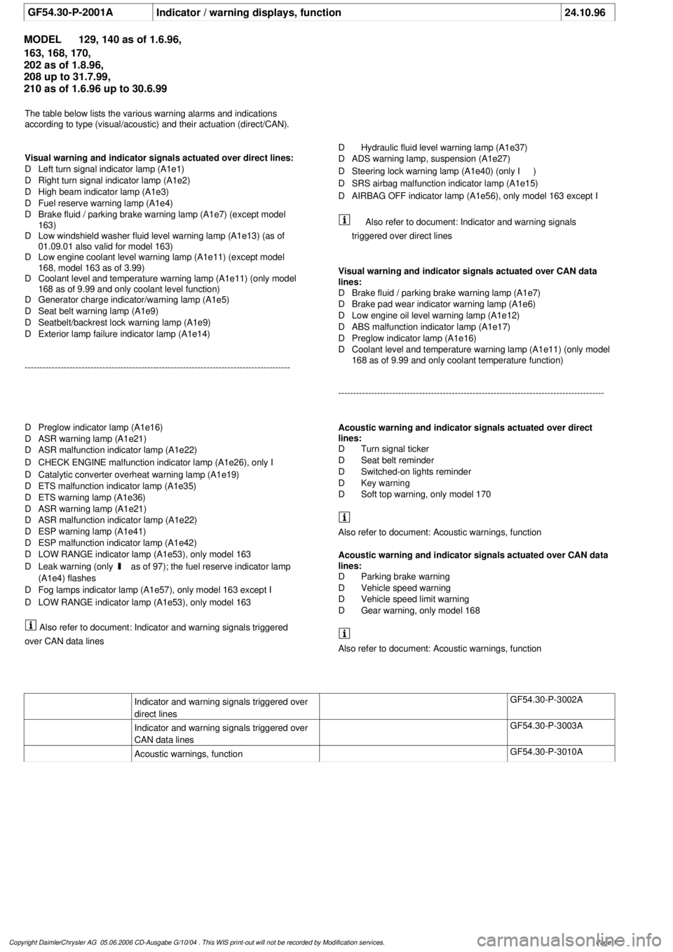
GF54.30-P-2001A
Indicator / warning displays, function
24.10.96
MODEL
129, 140 as of 1.6.96,
163, 168, 170,
202 as of 1.8.96,
208 up to 31.7.99,
210 as of 1.6.96 up to 30.6.99
The table below lists the various warning alarms and indications
according to type (visual/acoustic) and their actuation (direct/CAN).
Visual warning and indicator signals actuated over direct lines:
D
Left turn signal indicator lamp (A1e1)
D
Right turn signal indicator lamp (A1e2)
D
High beam indicator lamp (A1e3)
D
Fuel reserve warning lamp (A1e4)
D
Brake fluid / parking brake warning lamp (A1e7) (except model
163)
D
Low windshield washer fluid level warning lamp (A1e13) (as of
01.09.01 also valid for model 163)
D
Low engine coolant level warning lamp (A1e11) (except model
168, model 163 as of 3.99)
D
Coolant level and temperature warning lamp (A1e11) (only model
168 as of 9.99 and only coolant level function)
D
Generator charge indicator/warning lamp (A1e5)
D
Seat belt warning lamp (A1e9)
D
Seatbelt/backrest lock warning lamp (A1e9)
D
Exterior lamp failure indicator lamp (A1e14)
-----------------------------------------------------------------------------------------
D
Hydraulic fluid level warning lamp (A1e37)
D
ADS warning lamp, suspension (A1e27)
D
Steering lock warning lamp (A1e40) (only
I
)
D
SRS airbag malfunction indicator lamp (A1e15)
D
AIRBAG OFF indicator lamp (A1e56), only model 163 except
I
Also refer to document: Indicator and warning signals triggered
over CAN data lines
Acoustic warning and indicator signals actuated over direct
lines:
D
Turn signal ticker
D
Seat belt reminder
D
Switched-on lights reminder
D
Key warning
D
Soft top warning, only model 170
Also refer to document: Acoustic warnings, function
Acoustic warning and indicator signals actuated over CAN data
lines:
D
Parking brake warning
D
Vehicle speed warning
D
Vehicle speed limit warning
D
Gear warning, only model 168
Also refer to document: Acoustic warnings, function
Indicator and warning signals triggered over
direct lines
GF54.30-P-3002A
Indicator and warning signals triggered over
CAN data lines
GF54.30-P-3003A
Acoustic warnings, function
GF54.30-P-3010A
Copyright DaimlerChrysler AG 05.06.2006 CD-Ausgabe G/10/04 . This WIS print-out will not be recorde
d by Modification services.
Page 1
Page 3482 of 4133
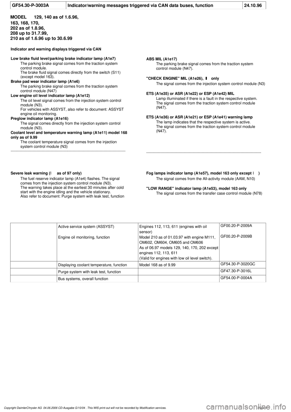
GF54.30-P-3003A
Indicator/warning messages triggered via CAN data buses, function
24.10.96
MODEL
129, 140 as of 1.6.96,
163, 168, 170,
202 as of 1.8.96,
208 up to 31.7.99,
210 as of 1.6.96 up to 30.6.99
Indicator and warning displays triggered via CAN
Low brake fluid level/parking brake indicator lamp (A1e7)
The parking brake signal comes from the traction system
control module.
The brake fluid signal comes directly from the switch (S11)
(except model 163).
Brake pad wear indicator lamp (A1e6)
The parking brake signal comes from the traction system
control module (N47)
Low engine oil level indicator lamp (A1e12)
The oil level signal comes from the injection system control
module (N3).
For vehicles with ASSYST, also refer to document: ASSYST
engine oil monitoring.
Preglow indicator lamp (A1e16)
The signal comes directly from the injection system control
module (N3).
Coolant level and temperature warning lamp (A1e11) model 168
only as of 9.99
The coolant temperature signal comes from the injection
system control module (N3)
-----------------------------------------------------------------------------------------
ABS MIL (A1e17)
The parking brake signal comes from the traction system
control module (N47).
"CHECK ENGINE" MIL (A1e26),
I
only
The signal comes from the injection system control module (N3)
ETS (A1e35) or ASR (A1e22) or ESP (A1e42) MIL
Lamp illuminated if there is a fault in the respective system.
The signal comes from the traction system control module
(N47).
ETS (A1e36) or ASR (A1e21) or ESP (A1e41) warning lamp
The lamp indicates that the respective system is active.
The signal comes from the traction system control module
(N47).
-----------------------------------------------------------------------------------------
Severe leak warning (
I
as of 97 only)
The fuel reserve indicator lamp (A1e4) flashes. The signal
comes from the injection system control module (N3).
The warning takes place at the earliest 30 minutes after cold
start with the engine idling and the vehicle stationary.
Also refer to document: Purge system with leak test, function
Fog lamps indicator lamp (A1e57), model 163 only except
I
)
The signal comes from the All-activity module (AAM, N10)
"LOW RANGE" indicator lamp (A1e53), model 163 only
The signal comes from the transfer case control module (N78)
Active service system (ASSYST)
Engines 112, 113, 611 (engines with oil
sensor)
GF00.20-P-2009A
Engine oil monitoring, function
Model 210 as of 01.03.97 with engine M111,
OM602, OM604, OM605 and OM606
As of 06.97 models 129, 140, 170, 202 except
engines 112, 113, 611
(Valid for engines with low oil level switch).
GF00.20-P-2009B
Displaying coolant temperature, function
Model 168 as of 9.99
GF54.30-P-3020GC
Purge system with leak test, function
GF47.30-P-3016L
Bus systems, overall function
GF54.00-P-0004A
Copyright DaimlerChrysler AG 04.06.2006 CD-Ausgabe G/10/04 . This WIS print-out will not be recorde
d by Modification services.
Page 1
Page 3483 of 4133
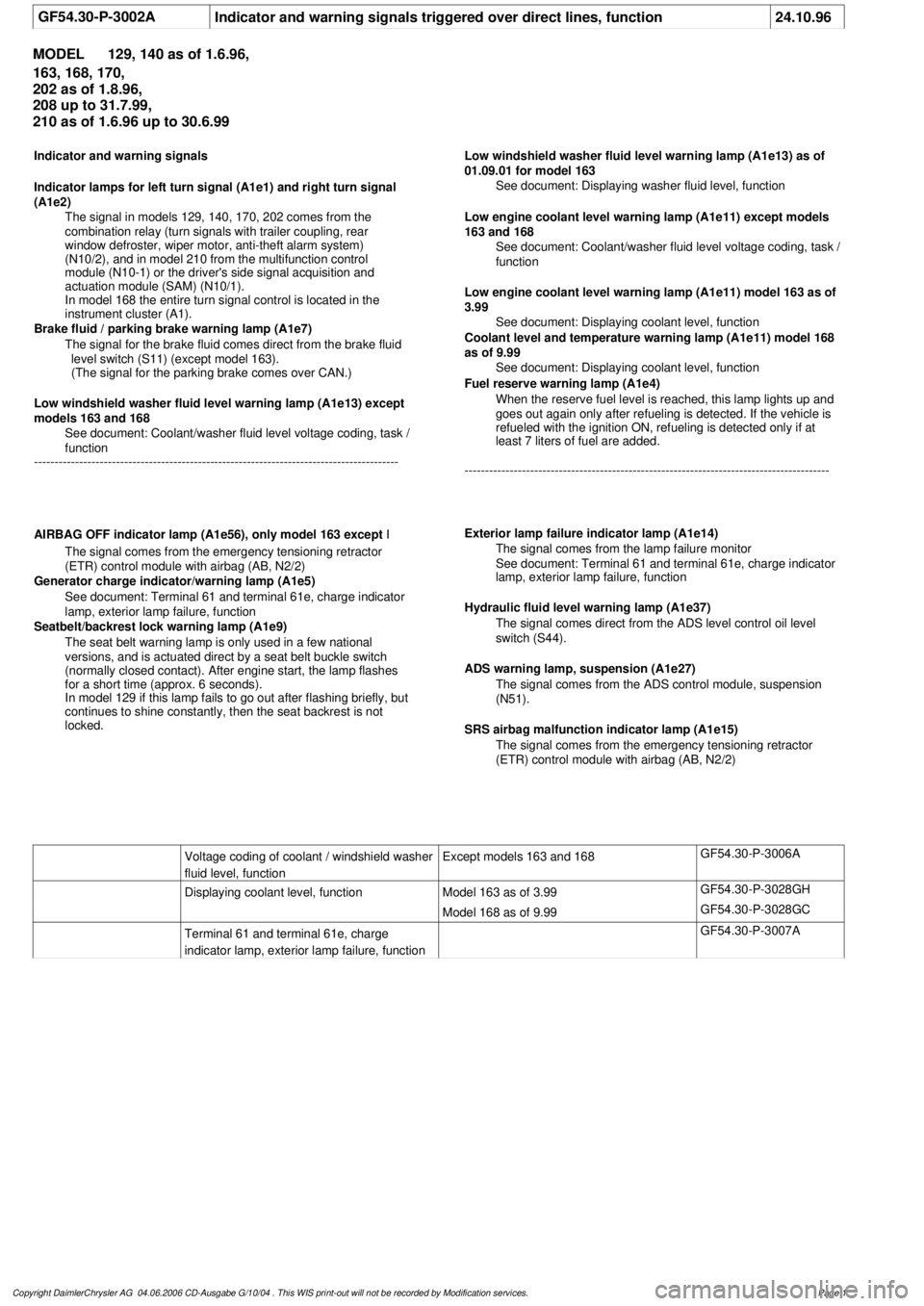
GF54.30-P-3002A
Indicator and warning signals triggered over direct lines, function
24.10.96
MODEL
129, 140 as of 1.6.96,
163, 168, 170,
202 as of 1.8.96,
208 up to 31.7.99,
210 as of 1.6.96 up to 30.6.99
Indicator and warning signals
Indicator lamps for left turn signal (A1e1) and right turn signal
(A1e2)
The signal in models 129, 140, 170, 202 comes from the
combination relay (turn signals with trailer coupling, rear
window defroster, wiper motor, anti-theft alarm system)
(N10/2), and in model 210 from the multifunction control
module (N10-1) or the driver's side signal acquisition and
actuation module (SAM) (N10/1).
In model 168 the entire turn signal control is located in the
instrument cluster (A1).
Brake fluid / parking brake warning lamp (A1e7)
The signal for the brake fluid comes direct from the brake fluid level switch (S11) (except model 163).
(The signal for the parking brake comes over CAN.)
Low windshield washer fluid level warning lamp (A1e13) except
models 163 and 168
See
document: Coolant/washer fluid level voltage coding, task /
function
-----------------------------------------------------------------------------------------
Low windshield washer fluid level warning lamp (A1e13) as of
01.09.01 for model 163
See document: Displaying washer fluid level, function
Low engine coolant level warning lamp (A1e11) except models
163 and 168
See
document: Coolant/washer fluid level voltage coding, task /
function
Low engine coolant level warning lamp (A1e11) model 163 as of
3.99
See
document: Displaying coolant level, function
Coolant level and temperature warning lamp (A1e11) model 168
as of 9.99
See
document: Displaying coolant level, function
Fuel reserve warning lamp (A1e4)
When the reserve fuel level is reached, this lamp lights up and
goes out again only after refueling is detected. If the vehicle is
refueled with the ignition ON, refueling is detected only if at
least 7 liters of fuel are added.
-----------------------------------------------------------------------------------------
AIRBAG OFF indicator lamp (A1e56), only model 163 except
I
The signal comes from the emergency tensioning retractor
(ETR) control module with airbag (AB, N2/2)
Generator charge indicator/warning lamp (A1e5)
See document: Terminal 61 and terminal 61e, charge indicator
lamp, exterior lamp failure, function
Seatbelt/backrest lock warning lamp (A1e9)
The seat belt warning lamp is only used in a few national
versions, and is actuated direct by a seat belt buckle switch
(normally closed contact). After engine start, the lamp flashes
for a short time (approx. 6 seconds).
In model 129 if this lamp fails to go out after flashing briefly, but
continues to shine constantly, then the seat backrest is not
locked.
Exterior lamp failure indicator lamp (A1e14)
The signal comes from the lamp failure monitor
See document: Terminal 61 and terminal 61e, charge indicator
lamp, exterior lamp failure, function
Hydraulic fluid level warning lamp (A1e37)
The signal comes direct from the ADS level control oil level
switch (S44).
ADS warning lamp, suspension (A1e27) The signal comes from the ADS control module, suspension
(N51).
SRS airbag malfunction indicator lamp (A1e15)
The signal comes from the emergency tensioning retractor
(ETR) control module with airbag (AB, N2/2)
Voltage coding of coolant / windshield washer
fluid level, function
Except models 163 and 168
GF54.30-P-3006A
Displaying coolant level, function
Model 163 as of 3.99
GF54.30-P-3028GH
Model 168 as of 9.99
GF54.30-P-3028GC
Terminal 61 and terminal 61e, charge
indicator lamp, exterior lamp failure, function
GF54.30-P-3007A
Copyright DaimlerChrysler AG 04.06.2006 CD-Ausgabe G/10/04 . This WIS print-out will not be recorde
d by Modification services.
Page 1
Page 3496 of 4133
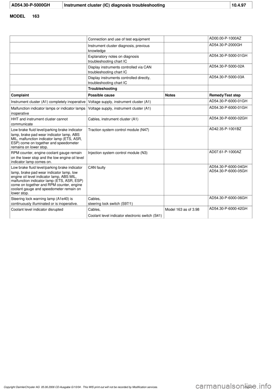
AD54.30-P-5000GH
Instrument cluster (IC) diagnosis troubleshooting
10.4.97
MODEL
163
Connection and use of test equipment
AD00.00-P-1000AZ
Instrument cluster diagnosis, previous
knowledge
AD54.30-P-2000GH
Explanatory notes on diagnosis
troubleshooting chart IC
AD54.30-P-5000-01GH
Display instruments controlled via CAN
troubleshooting chart IC
AD54.30-P-5000-02A
Display instruments controlled directly,
troubleshooting chart IC
AD54.30-P-5000-03A
Troubleshooting
Complaint
Possible cause
Notes
Remedy/Test step
Instrument cluster (A1) completely inoperative
Voltage supply, instrument cluster (A1)
AD54.30-P-6000-01GH
Malfunction indicator lamps or indicator lamps
inoperative
Voltage supply, instrument cluster (A1)
AD54.30-P-6000-01GH
HHT and instrument cluster cannot
communicate
Cables, instrument cluster (A1)
AD54.30-P-6000-02GH
Low brake fluid level/parking brake indicator
lamp, brake pad wear indicator lamp, ABS
MIL, malfunction indicator lamp (ETS, ASR,
ESP) come on together and speedometer
remains on lower stop.
Traction system control module (N47)
AD42.35-P-1001BZ
RPM counter, engine coolant gauge remain
on the lower stop and the low engine oil level
indicator lamp comes on.
Injection system control module (N3)
AD07.61-P-1000AZ
Low brake fluid level/parking brake indicator
lamp, brake pad wear indicator lamp, low
engine oil level indicator lamp, ABS MIL,
malfunction indicator lamp (ETS, ASR, ESP)
come on together and RPM counter, engine
coolant gauge and speedometer remain on
lower stop.
CAN faulty
AD54.30-P-6000-04GH
AD54.30-P-6000-05GH
Steering lock warning lamp (A1e40) is
continuously illuminated or is inoperative.
Cables,
steering lock switch (S97/1)
AD54.30-P-6000-06GH
Coolant level indicator disrupted
Cables,
Coolant level indicator electronic switch (S41)
Model 163 as of 3.98
AD54.30-P-6000-42GH
Copyright DaimlerChrysler AG 05.06.2006 CD-Ausgabe G/10/04 . This WIS print-out will not be recorde
d by Modification services.
Page 1