warning MERCEDES-BENZ ML430 2002 W163 User Guide
[x] Cancel search | Manufacturer: MERCEDES-BENZ, Model Year: 2002, Model line: ML430, Model: MERCEDES-BENZ ML430 2002 W163Pages: 342, PDF Size: 13.75 MB
Page 71 of 342
68 Restraint systems
Te ch n i c a l
data Instruments
and controlsOperationDrivingInstrument
cluster displayPractical hints Car care Index
Infant and child restraint systems
We recommend that all infants and children be properly
restrained at all times while the vehicle is in motion. All
lap-shoulder belts except the driver’s seat belt have
special seat belt retractors for secure fastening of child
restraints.
To fasten a child restraint follow child restraint
instructions for routing. Then pull shoulder belt out
completely and let it retract. During the seat belt
retraction a ratcheting sound can be heard to indicate
that the special seat belt retractor is activated. The belt
is now locked. Push down on child restraint to take up
any slack.
To deactivate, release seat belt buckle and let seat belt
retract completely. The seat belt can again be used in
the usual manner.
Note:
For child seats with mounting fittings for tether
anchorages refer to page 70 (installation of infant and
child restraint systems).Important!
The use of infant or child restraints is required by law in
all 50 states and all Canadian provinces.
Infants and small children should be seated in an
appropriate infant or child restraint system properly
secured by a lap-shoulder belt, and that complies with
U.S. Federal Motor Vehicle Safety Standard 213 and
Canadian Motor Vehicle Safety Standard 213.
A statement by the child restraint manufacturer of
compliance with this standard can be found on the
instruction label on the restraint and in the instruction
manual provided with the restraint.
When using any infant or child restraint system, be sure
to carefully read and follow all manufacturer’s
instructions for installation and use.
Please read and observe warning labels affixed to inside
of vehicle and to infant or child restraints.
Wa r n i n g !
Never release the seat belt buckle while vehicle is
in motion, since the special seat belt retractor will
be deactivated.
Page 86 of 342
83 Instrument cluster
Te ch n i c a l
data Instruments
and controlsOperationDrivingInstrument
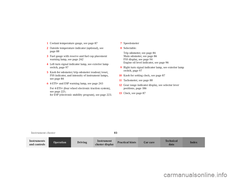
cluster displayPractical hints Car care Index 1Coolant temperature gauge, see page 87
2Outside temperature indicator (optional), see
page 88
3Fuel gauge with reserve and fuel cap placement
warning lamp, see page 242
4Left turn signal indicator lamp, see exterior lamp
switch, page 97
5Knob for odometer / trip odometer readout / reset,
FSS indicator, and intensity of instrument lamps,
see page 86
64-ETS+ and ESP warning lamp, see page 243
For 4-ETS+ (four wheel electronic traction system),
seepage221;
for ESP (electronic stability program), see page 223.7Speedometer
8Selectable:
Trip odometer, see page 86
Main odometer, see page 86
FSS display, see page 94
Engine oil level indicator, see page 96
9Right turn signal indicator lamp, see exterior lamp
switch, page 97
10Knob for setting clock, see page 87
11Tachometer, see page 88
12Gear range indicator display, see selector lever
positions, page 186
13Clock, see page 87
Page 91 of 342
88 Instrument cluster
Te ch n i c a l
data Instruments
and controlsOperationDrivingInstrument
cluster displayPractical hints Car care Index
Outside temperature indicator (2)
The temperature sensor is located in the front bumper
area. Due to its location, the sensor can be affected by
road or engine heat during idling or slow driving. This
means that the accuracy of the displayed temperature
can only be verified by comparison to a thermometer
placed next to the sensor, not by comparison to external
displays (e.g. bank signs etc.).
Adaptation to ambient temperature takes place in steps
and depends on the prevailing driving conditions (stop-
and-go or moderate, constant driving) and amount of
temperature change.Tachometer (11)
The tachometer displays the present engine speed in
revolutions per minute (RPM).
To help protect the engine, the fuel supply is interrupted
if the engine is operated above its specified limit.
Wa r n i n g !
The outside temperature indicator is not designed
to serve as an Ice-Warning Device and is therefore
unsuitable for that purpose. Indicated
temperatures just above the freezing point do not
guarantee that the road surface is free of ice.
Page 97 of 342
94 Flexible service system
Te ch n i c a l
data Instruments
and controlsOperationDrivingInstrument
cluster displayPractical hints Car care Index
Flexible service system (FSS)
(service indicator)
The FSS permits a flexible service schedule that is
directly related to the operating conditions of the
vehicle.
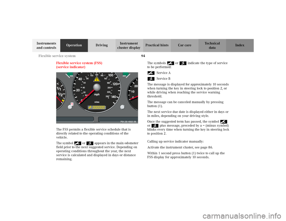
The symbol 9 or ´ appears in the main odometer
field prior to the next suggested service. Depending on
operating conditions throughout the year, the next
service is calculated and displayed in days or distance
remaining.The symbols 9 or ´ indicate the type of service
to be performed:
9Service A
´Service B
The message is displayed for approximately 10 seconds
when turning the key in steering lock to position 2, or
while driving when reaching the service warning
threshold.
The message can be canceled manually by pressing
button (1).
The next service due date is displayed either in days or
in miles, depending on your driving style.
Once the suggested term has passed, the symbol 9
or ´ plus message, preceded by a – (minus symbol)
blinks every time when turning the key in steering lock
to position 2.
Calling up service indicator manually:
Activate the instrument cluster, see page 86.
Within 1 second press button (1) twice to call up the
FSS display for approximately 10 seconds.
Page 101 of 342
98 Exterior lamp switch
Te ch n i c a l
data Instruments
and controlsOperationDrivingInstrument
cluster displayPractical hints Car care Index
Turn signal failure
If one of the turn signals fails, the turn signal indicator
system flashes and sounds at a faster than normal rate.Standing lamps
When the vehicle is parked on the street the standing
lamps (right or left side parking lamps) can be turned
on, making the vehicle more visible to passing vehicles.
The standing lamps cannot be operated with the key in
steering lock position 1 or 2.
Note:
With the key removed and a front door open, a warning
sounds if the vehicle’s exterior lamps (except standing
lamps) are not switched off.
Page 107 of 342
104 Hazard warning flasher
Te ch n i c a l
data Instruments
and controlsOperationDrivingInstrument
cluster displayPractical hints Car care Index
Hazard warning flasher switch
The hazard warning flasher switch is located on top of
the steering column.
The hazard warning flasher can be activated either
manually via the switch located in the dashboard, or it
is activated automatically at the time an airbag is
deployed.
To activate hazard warning flasher, press switch once.
To deactivate, press switch again.
Note:
To signal turns while being towed with hazard warning
flasher in use, turn key in steering lock to position 2
and activate combination switch for left or right turn
signal in usual manner. Now deactivate the hazard
warning flasher, only the selected turn signal will
operate. Upon canceling the turn signal, the hazard
warning flasher must be activated again.Headlamp cleaning system (with Xenon headlamps)
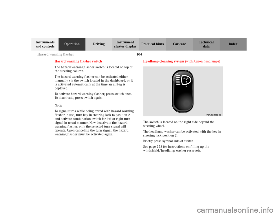
The switch is located on the right side beyond the
steering wheel.
The headlamp washer can be activated with the key in
steering lock position 2.
Briefly press symbol side of switch.
See page 258 for instructions on filling up the
windshield / headlamp washer reservoir.
Page 184 of 342
181 Steering lock
Te ch n i c a l
data Instruments
and controlsOperationDrivingInstrument
cluster displayPractical hints Car care Index Caution!
To prevent accelerated battery discharge and a possible
dead battery, always remove the key from the steering
lock. Do not leave the key in steering lock position 0.
Notes:
A warning sounds when the driver’s door is opened
while the key is in steering lock position 1 or 0.
With the engine at idle speed, the charging rate of the
alternator (output) is limited.It is therefore recommended that you turn off
unnecessary electrical consumers while driving in stop-
and-go traffic. This precaution helps to avoid draining of
the battery.
Unnecessary strain on the battery and charging system
may be minimized by turning off the following power
consumers, for example: Heated seats, rear window
defroster.
Page 194 of 342
191 Parking brake
Te ch n i c a l
data Instruments
and controlsOperationDrivingInstrument
cluster displayPractical hints Car care Index Parking brake
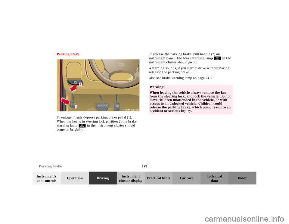
To engage, firmly depress parking brake pedal (1).
When the key is in steering lock position 2, the brake
warning lampÉ in the instrument cluster should
come on brightly.To release the parking brake, pull handle (2) on
instrument panel. The brake warning lampÉ in the
instrument cluster should go out.
A warning sounds, if you start to drive without having
released the parking brake.
Also see brake warning lamp on page 241.
Wa r n i n g !
When leaving the vehicle always remove the key
from the steering lock, and lock the vehicle. Do not
leave children unattended in the vehicle, or with
access to an unlocked vehicle. Children could
release the parking brake, which could result in an
accident or serious injury.
Page 196 of 342
193 Driving instructions
Te ch n i c a l
data Instruments
and controlsOperationDrivingInstrument
cluster displayPractical hints Car care Index Power assistance
BrakesExcessive use of road salt and other snow melting
chemicals spread on roads during the winter months
may cause a build up of moisture or residue to form on
the braking components. This build up or residue could
cause light corrosion of the braking components if the
vehicle is parked with the brakes cold. Apply steady and
even braking pressure when stopping the vehicle to
warm up and dry the brake components.
Important!
Please pay attention to the function of the brake assist
system (BAS), see page 217.
The condition of the parking brake system is checked
each time the vehicle is in the shop for the required
maintenance service.
If the parking brake is released and the brake warning
lamp in the instrument cluster stays on and there is no
audible warning (EBP), the brake fluid level in the
reservoir is too low.
Brake pad wear or a leak in the system may be the
reason for low brake fluid in the reservoir.
Have the brake system inspected at an authorized
Mercedes-Benz Light Truck Center immediately.
Wa r n i n g !
When the engine is not running, the brake and
steering systems are without power assistance.
Under these circumstances, a much greater effort is
necessary to stop or steer the vehicle.Wa r n i n g !
After driving in heavy rain for some time without
applying the brakes or through water deep enough
to wet brake components or salty road conditions,
the first braking action may be somewhat reduced
and increased pedal pressure may be necessary to
obtain expected braking effect. Be sure to maintain
a safe distance from vehicles in front.Resting your foot on the brake pedal will cause
excessive and premature wear of the brake pads.It can also result in the brakes overheating thereby
significantly reducing their effectiveness. It may
not be possible to stop the vehicle in sufficient time
to avoid an accident.
Page 198 of 342
195 Driving instructions
Te ch n i c a l
data Instruments
and controlsOperationDrivingInstrument
cluster displayPractical hints Car care Index Parking
Important!
It is advisable to set the parking brake whenever
parking or leaving the vehicle. In addition, move
selector lever to position “P”.
When parking on hills, always set the parking brake.Tires
Tread wear indicators (TWI) are required by law. These
indicators are located in six places on the tread
circumference and become visible at a tread depth of
approximately
1/16in (1.5 mm), at which point the tire is
considered worn and should be replaced.
The tread wear indicator appears as a solid band across
the tread.
Wa r n i n g !
To reduce the risk of personal injury as a result of
vehicle movement, before
turning off the engine
and leaving the vehicle, always:
1. Keep right foot on the service brake pedal.
2. Firmly depress parking brake pedal.
3. Move the selector lever to position “P”.
4. Slowly release the service brake pedal.
5. Turn front wheels towards the road curb.
6. Turn the key to steering lock position 0 and
remove.
7. Take the key and lock vehicle when leaving.
Wa r n i n g !
If you feel a sudden significant vibration or ride
disturbance, or you suspect that possible damage to
your vehicle has occurred, you should turn on the
hazard warning flashers, carefully slow down, and
drive with caution to an area which is a safe
distance from the roadway.Inspect the tires and under the vehicle for possible
damage. If the vehicle or tires appear unsafe, have
it towed to the nearest Mercedes-Benz Light Truck
Center or tire dealer for repairs.