check engine light MERCEDES-BENZ ML500 1997 Complete Owner's Manual
[x] Cancel search | Manufacturer: MERCEDES-BENZ, Model Year: 1997, Model line: ML500, Model: MERCEDES-BENZ ML500 1997Pages: 4133, PDF Size: 88.89 MB
Page 274 of 4133
224 Malfunction and indicator lamps
Te ch n ica l
data Instruments
and controlsOperation DrivingInstrument
cluster displayPractical hints Car care Index
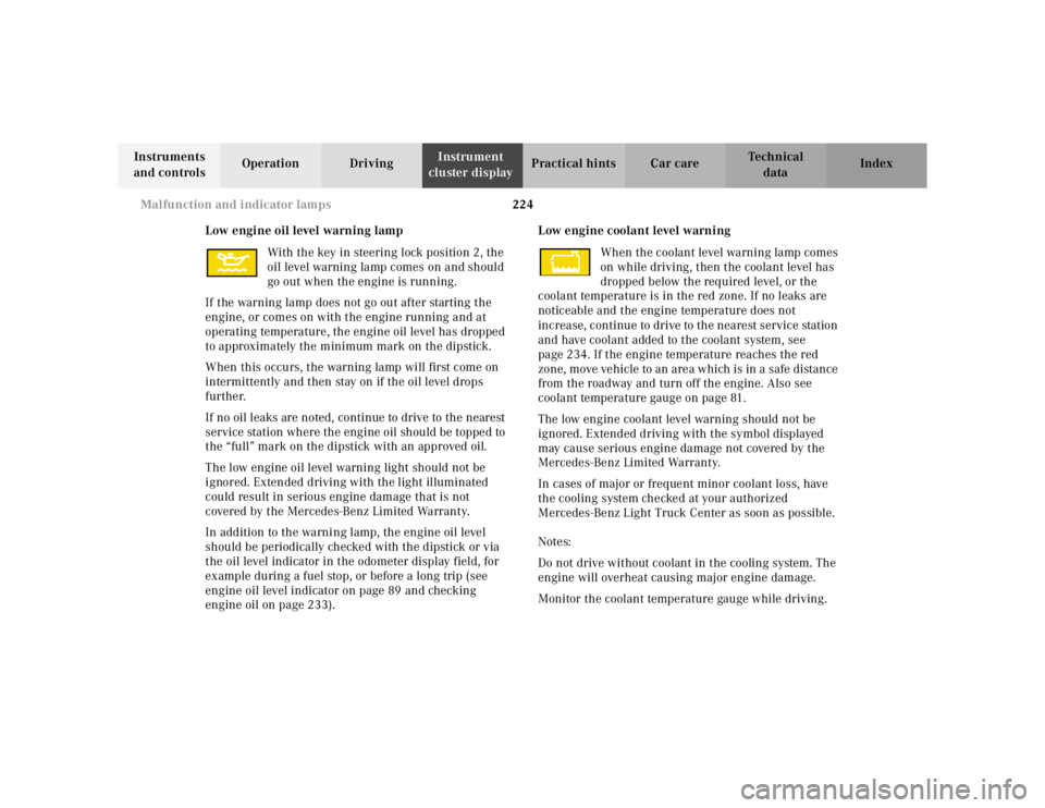
Low engine oil level warning lamp
With the key in steering lock position 2, the
oil level warning lamp comes on and should
go out when the engine is running.
If the warning lamp does not go out after starting the
engine, or comes on with the engine running and at
operating temperature, the engine oil level has dropped
to approximately the minimum mark on the dipstick.
When this occurs, the warning lamp will first come on
intermittently and then stay on if the oil level drops
further.
If no oil leaks are noted, continue to drive to the nearest
service station where the engine oil should be topped to
the “full” mark on the dipstick with an approved oil.
The low engine oil level warning light should not be
ignored. Extended driving with the light illuminated
could result in serious engine damage that is not
covered by the Mercedes-Benz Limited Warranty.
In addition to the warning lamp, the engine oil level
should be periodically checked with the dipstick or via
the oil level indicator in the odometer display field, for
example during a fuel stop, or before a long trip (see
engine oil level indicator on page 89 and checking
engine oil on page 233).Low engine coolant level warning
When the coolant level warning lamp comes
on while driving, then the coolant level has
dropped below the required level, or the
coolant temperature is in the red zone. If no leaks are
noticeable and the engine temperature does not
increase, continue to drive to the nearest service station
and have coolant added to the coolant system, see
page 234. If the engine temperature reaches the red
zone, move vehicle to an area which is in a safe distance
from the roadway and turn off the engine. Also see
coolant temperature gauge on page 81.
The low engine coolant level warning should not be
ignored. Extended driving with the symbol displayed
may cause serious engine damage not covered by the
Mercedes-Benz Limited Warranty.
In cases of major or frequent minor coolant loss, have
the cooling system checked at your authorized
Mercedes-Benz Light Truck Center as soon as possible.
Notes:
Do not drive without coolant in the cooling system. The
engine will overheat causing major engine damage.
Monitor the coolant temperature gauge while driving.
Page 275 of 4133
225 Malfunction and indicator lamps
Te ch n ica l
data Instruments
and controlsOperation DrivingInstrument
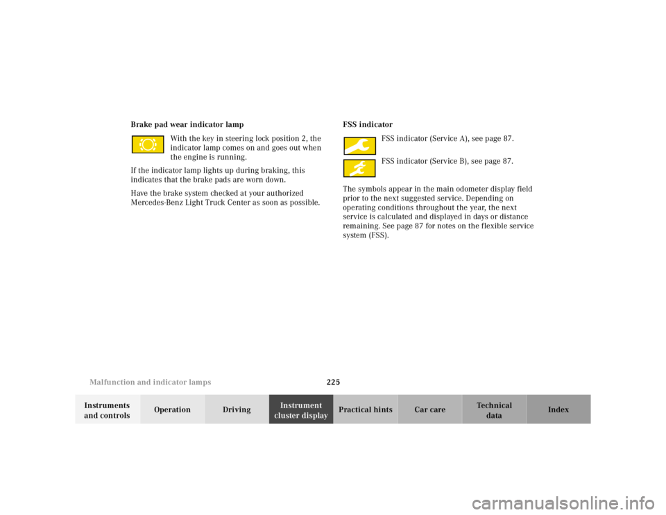
cluster displayPractical hints Car care Index Brake pad wear indicator lamp
With the key in steering lock position 2, the
indicator lamp comes on and goes out when
the engine is running.
If the indicator lamp lights up during braking, this
indicates that the brake pads are worn down.
Have the brake system checked at your authorized
Mercedes-Benz Light Truck Center as soon as possible.FSS indicator
FSS indicator (Service A), see page 87.
FSS indicator (Service B), see page 87.
The symbols appear in the main odometer display field
prior to the next suggested service. Depending on
operating conditions throughout the year, the next
service is calculated and displayed in days or distance
remaining. See page 87 for notes on the flexible service
system (FSS).
Page 284 of 4133
234 Engine compartment
Te ch n ica l
data Instruments
and controlsOperation DrivingInstrument
cluster displayPractical hintsCar care Index
Automatic transmission fluid level
The transmission has a permanent fill of automatic
transmission fluid.
Regular automatic transmission fluid level checks and
changes are not required. For this reason the dipstick is
omitted.
If you notice fluid leaks or gear shifting malfunctions,
have your authorized Mercedes-Benz Light Truck Center
check the transmission fluid level.
Engine oil consumption
Engine oil consumption checks should only be made
after the break-in period. During the break-in period,
higher oil consumption may be noticed and is normal.
Frequent driving at high engine speeds results in
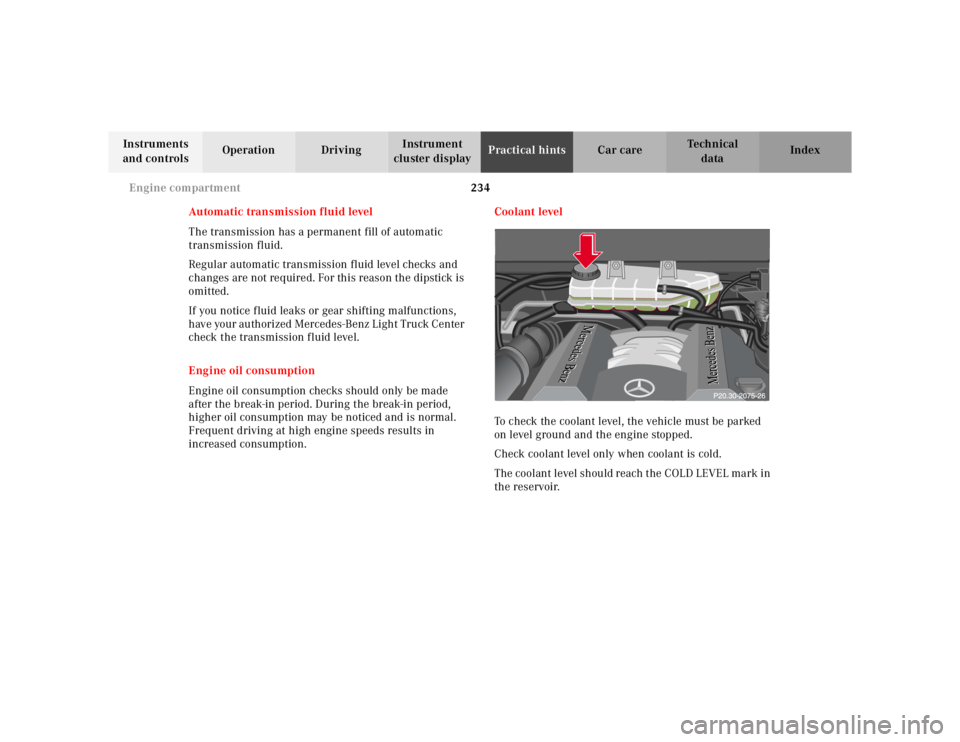
increased consumption.Coolant level
To check the coolant level, the vehicle must be parked
on level ground and the engine stopped.
Check coolant level only when coolant is cold.
The coolant level should reach the COLD LEVEL mark in
the reservoir.P20.30-0241-20
Page 304 of 4133
254 Jump starting
Te ch n ica l
data Instruments
and controlsOperation DrivingInstrument
cluster displayPractical hintsCar care Index
Proceed as follows:
1. Position the vehicle with the charged battery so that
the jumper cables will reach, but never let the
vehicles touch. Make sure the jumper cables do not
have loose or missing insulation.
2. On both vehicles:
•Turn off engine and all lights and accessories,
except hazard warning flashers or work lights.
•Apply parking brake and shift selector lever to
position “P”.
Important!
3. Clamp one end of the first jumper cable to the
positive (+) under hood terminal of the discharged
battery and the other end to the positive (+) terminal
of the charged battery. Make sure the cable clamps
do not touch any other metal parts.
4. Clamp one end of the second jumper cable to the
grounded negative (–) terminal of the charged
battery and the final connection to the negative (–)
terminal of the discharged battery.Important!
5. Start engine of the vehicle with the charged battery
and run at high idle. Make sure the cables are not
on or near pulleys, fans, or other parts that move
when the engine is started. Allow the discharged
battery to charge for a few minutes. Start engine of
the disabled vehicle in the usual manner.
6. After the engine has started, remove jumper cables
by exactly reversing the above installation
sequence, starting with the last connection made
first. When removing each clamp, make sure that it
does not touch any other metal while the other end
is still attached.
Notes:
If engine does not run after several unsuccessful
starting attempts, have it checked at the nearest
authorized Mercedes-Benz Light Truck Center.
Excessive unburned fuel may damage the catalytic
converter.
Page 347 of 4133
297 Fuels, coolants, lubricants etc.
Te ch n ica l
data Instruments
and controlsOperation DrivingInstrument
cluster displayPractical hints Car care Index the engine temperature will increase due to the lower
heat transfer capability of the solution. Therefore, do not
use more than this amount of anticorrosion / antifreeze.
If the coolant level is low, water and MB anticorrosion/
antifreeze should be used to bring it up to the proper
level (have cooling system checked for signs of leakage).
The water in the cooling system must meet minimum
requirements, which are usually satisfied by normal
drinking water. If your are not sure about the water
quality, consult your authorized Mercedes-Benz Light
Truck Center.
Anticorrosion/antifreeze
Your vehicle contains a number of aluminum parts. The
use of aluminum components in motor vehicle engines
necessitates that anticorrosion / antifreeze coolant used
in such engines be specifically formulated to protect the
aluminum parts. (Failure to use such anticorrosion/
antifreeze coolant will result in a significantly
shortened service life.)
Therefore the following product is strongly
recommended for use in your vehicle: Mercedes-Benz
Anticorrosion / antifreeze agent.Before the start of the winter season (or once a year in
the hot southern regions), you should have the
anticorrosion / antifreeze concentration checked. The
coolant is also regularly checked each time you bring
your vehicle to your authorized Mercedes-Benz Light
Truck Center for service.
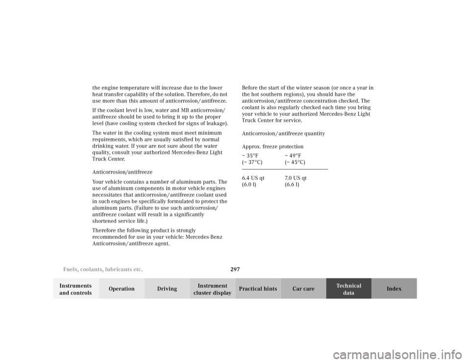
Anticorrosion / antifreeze quantity
Approx. freeze protection
– 35°F
(– 37°C)– 49°F
(– 45°C)
6.4 US qt
(6.0 l)7. 0 U S q t
(6.6 l)
Page 379 of 4133
module.
2. To install air bag module, reverse removal procedur e. Activate air bag system. Perform system operation
check to ensure system is functioning properly. See SYSTEM OPERATION CHECK
.
Removal & Installation (SLK 320)
1. Before proceeding, See AIR BAG SAFETY PRECAUTIONS . Disable air bag system. See
DISABLING & ACTIVATI NG AIR BAG SYSTEM
. Remove ignition key. Remove top section of
instrument panel. Fold vapor barrier toward front to reveal 2 screws. Disconnect passenger-side air bag
module connector. Remove 4 screws and passenger-side air bag module.
2. To install air bag module, reverse removal procedur e. Activate air bag system. Perform system operation
check to ensure system is functioning properly. See SYSTEM OPERATION CHECK
.
DIAGNOSTICS
Before proceeding, see AIR BAG SAFETY PRECAUTIONS
. The SRS control module is capable of
diagnosing air bag system components and ETR components. If a fault is detected by the SRS control module
or system is malfunctioning, SRS warning light will do one or more of the following:
SRS warning light goes out after 2 minutes. System fault is noted, however occupant protection is not
affected. See RETRIEVING FAULT CODES
.
SRS warning light illuminates cont inuously. System is faulty which may result in a non deployment or
false deployment. See RETRIEVING FAULT CODES
.
SRS warning light blinks continuous ly. Control module has been replaced without setting control module
parameters.
RETRIEVING FAULT CODES
1. Check vehicle fuses. Replace any blown fuses as nece ssary. Ensure vehicle battery voltage is 11 volts or
more. Ensure SRS warning light functions. Turn i gnition off. Connect Hand-Held Tester (HHT) (965 589
00 01) to Data Link Connector (DLC).
2. DLC is located in right rear corner of engine comp artment. It may be necessary to use Adapter (965 589
00 40 or 965 589 00 50) to connect HHT to DLC. Afte r HHT displays module number and version, press
return key to start diagnosis. Us ing HHT, follow HHT prompts to re trieve SRS fault codes. For SRS
control modules beginning with number 000, fault c ode 1 is valid. For SRS control modules beginning
with number 001, fault code 2 is valid. See Fig. 6
.
3. HHT will display a 3 digit fault code, and may display additional graphic information. This additional
graphic information will help in diagnosis of fault code. See Fig. 5
. During diagnosis HHT will display 4
different graphic displays info rming technician if a test passes or fail s, or if seat belt buckle is latched or
NOTE: After component replacement, perf
orm a system operation check to ensure
proper system operation. S ee SYSTEM OPERATION CHECK
.
NOTE: Fault codes may only be retrieved us ing Hand-Held Tester (965 589 00 01) and
Adapter (965 589 00 40 or 965 589 00 50).
2001 Mercedes-Benz ML320
2000-01 ACCESSORIES/SAFETY EQUIPMENT Merc edes-Benz - Air Bag Restraint Systems
me
Saturday, October 02, 2010 3:44:45 PMPage 15 © 2006 Mitchell Repair Information Company, LLC.
Page 384 of 4133
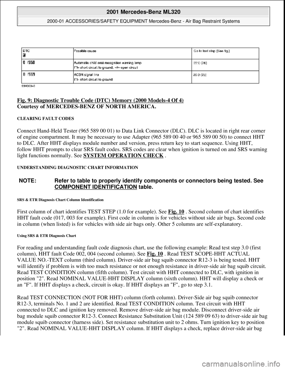
Fig. 9: Diagnostic Trouble Code (DTC) Memory (2000 Models-4 Of 4)
Courtesy of MERCEDES-BENZ OF NORTH AMERICA.
CLEARING FAULT CODES
Connect Hand-Held Tester (965 589 00 01) to Data Link Connector (DLC). DLC is located in right rear corner
of engine compartment. It may be necessary to use Adapter (965 589 00 40 or 965 589 00 50) to connect HHT
to DLC. After HHT displa ys module number and version, press return key to start sequence. Using HHT,
follow HHT prompts to clear SRS faul t codes. SRS codes are clear when ignition is turned on and SRS warning
light functions normally. See SYSTEM OPERATION CHECK
.
UNDERSTANDING DIAGNOSTIC CHART INFORMATION
SRS & ETR Diagnosis Chart Column Identification
First column of chart identifies TEST STEP (1.0 for example). See Fig. 10 . Second column of chart identifies
HHT fault code (017, 003 for example). First code in column is for ve hicles without side air bags. Second code
in column (when listed) is for ve hicles with side air bags only. Ot her 5 columns are self-explanatory.
Using SRS & ETR Diagnosis Chart
For reading and understanding fault code diagnosis chart, use the following example: Read test step 3.0 (first
column), HHT fault Code 002, 004 (second column). See Fig. 10
. Read TEST SCOPE-HHT ACTUAL
VALUE NO.-TEXT column (third column). Driver-side air bag squib connector R12-3 is being tested. HHT
will identify if problem is with too much resistance or not enough resistance in driver-side air bag squib circuit.
Read TEST CONDITION column (fifth column). Test ci rcuit with HHT connected to DLC, with ignition in
position "2". Read NOMINAL VALUE-HHT DISPLAY column (sixth column). HHT will display a check or
an "F". If HHT displays a check, circuit is okay. If HHT displays an "F", go to step 3.1.
Read TEST CONNECTION (NOT FOR HHT) column (fort h column). Driver-Side air bag squib connector
R12-3, terminals No. 1 and 2 are id entified. Read TEST CONDITION column. Test circuit with HHT
connected to DLC and igni tion key removed. Remove driver-side air bag module. Disconnect driver-side air
bag module squib connector R12-3. Conn ect Resistance Substitution Unit (124 589 09 63) to driver-side air bag
module squib connector (harness side). Set resistance substitution unit to 2 ohms. Turn ignition key to position
"2". Read NOMINAL VALUE-HHT DISPLAY column. If HHT displa
ys a check, replace driver-side air bag
NOTE: Refer to table to properly identify components or connectors being tested. See
COMPONENT IDENTIFICATION
table.
2001 Mercedes-Benz ML320
2000-01 ACCESSORIES/SAFETY EQUIPMENT Merc edes-Benz - Air Bag Restraint Systems
me
Saturday, October 02, 2010 3:44:46 PMPage 20 © 2006 Mitchell Repair Information Company, LLC.
Page 556 of 4133
89
Engine oil level indicator
Te ch n ica l
data
Instruments
and controls Operation
Driving Instrument
cluster display Practical hints Car care Index
Engine oil level indicator
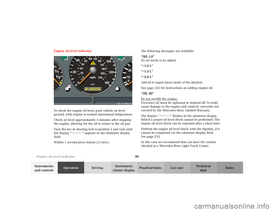
To check the engine oil level, park vehicle on level
ground, with engine at normal operational temperature.
Check oil level approximately 5 minutes after stopping
the engine, allowing for the oil to return to the oil pan.
Turn the key in steering lock to position 2 and wait until
the display “––––––” appears in the odometer display
field.
Within 1 second press button (1) twice. The following messages are available:
“OIL i.O”
No oil needs to be added.
“–1.0 L”
“–1.5 L”
“–2.0 L”
Add oil to upper (max) mark of the dipstick.
See page 233 for instructions on adding engine oil.
“OIL HI”
Do not overfill the engine.
Excessive oil must be siphoned or drained off. It could
cause damage to the engine and catalytic converter not
covered by the Mercedes-Benz Limited Warranty.
The display “––––––” flashes in the odometer display
field if a proper oil level check cannot be performed. The
engine oil level check can be repeated after a short time.
Perform the engine oil level check with the dipstick, if it
cannot be completed via the odometer display field.
See page 233.
In this case we recommend that you have the system
checked at a Mercedes-Benz Light Truck Center.
Page 614 of 4133
147
The first 1 000 miles
Te ch n ica l
data
Instruments
and controls Operation
Driving Instrument
cluster display Practical hints Car care Index
The first 1 000 miles (1 500 km)
The more cautiously you treat your vehicle during the
break-in period, the more satisfied you will be with its
performance later on. Therefore, drive your vehicle
during the first 1 000 miles (1 500 km) at moderate
vehicle and engine speeds.
During this period, avoid heavy loads (full throttle
driving) and excessive engine speeds.
Avoid accelerating by kickdown. It is not recommended
to brake the vehicle by manually shifting to a lower gear.
We recommend that you select positions “3”, “2” or “1”
only at moderate speeds (for hill driving).
After 1 000 miles (1 500 km) speeds may be gradually
increased to the permissible maximum. Maintenance
Approximately 30 days or 2 000 miles
(Canada: 2000 km) prior to the next recommended
service, the remaining distance or days are displayed in
the multifunction indicator. See Flexible Service System
(FSS) on page 87.
We strongly recommend that you have your vehicle
serviced by your authorized Mercedes-Benz Light Truck
Center, in accordance with the Service Booklet at the
times called for by the FSS.
Failure to have the vehicle maintained in accordance
with the Service Booklet at the designated times /
mileage may result in vehicle damage not covered by
the Mercedes-Benz Limited Warranty.
Check regularly and before a long trip, see page 215.
Page 631 of 4133
164
Starting and turning off the engine
Te ch n ica l
data
Instruments
and controls Operation
Driving Instrument
cluster display Practical hints Car care Index
Starting and turning off the engine
Before starting
Ensure that parking brake is engaged and that selector
lever is in position “P” or “N”. Turn key in steering lock
to position 2. The charge indicator lamp should come on.
Starting
Do not depress accelerator.
Briefly turn key in steering lock clockwise to the stop
and release. The starter will engage until the engine is
running.
If engine will not run, and the starting procedure stops,
turn key completely to the left and repeat starting the
engine.
After several unsuccessful attempts, have the system
checked at the nearest authorized Mercedes-Benz Light
Truck Center.
A starting procedure can be interrupted by turning the
key to steering lock position 0. Important!
Due to the installed starter non-repeat feature, the key
must be turned completely to the left before attempting
to start the engine again.
In areas where temperatures frequently drop below -4 °F
(-20 °C) we recommend that an engine block heater be
installed. Your authorized Mercedes-Benz Light Truck
Center will advise you on this subject.
Note:
In case the engine cannot be started and the
messages Á and î are shown in the odometer
display field, the system is not operational. Contact an
authorized Mercedes-Benz Light Truck Center or call
1-800-FOR-MERCedes (in the USA), or 1-800-387-0100
(in Canada).
Turning off
Turn the key in the steering lock to position 0 to stop the
engine.
The key can only be removed with the selector lever in
position “P”.