heating MERCEDES-BENZ ML500 1997 Complete Owner's Guide
[x] Cancel search | Manufacturer: MERCEDES-BENZ, Model Year: 1997, Model line: ML500, Model: MERCEDES-BENZ ML500 1997Pages: 4133, PDF Size: 88.89 MB
Page 1489 of 4133
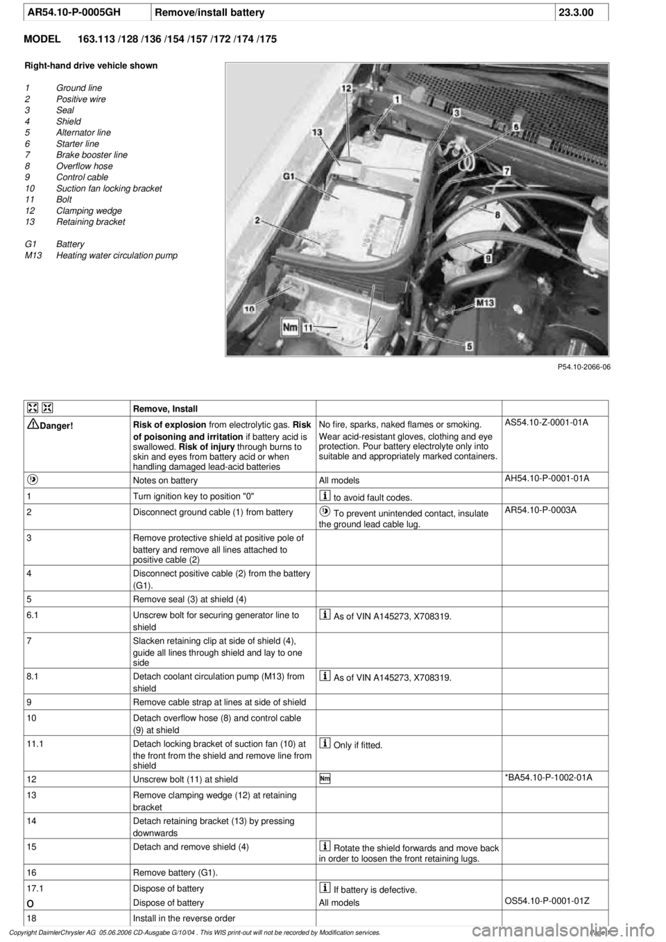
AR54.10-P-0005GH
Remove/install battery
23.3.00
MODEL
163.113 /128 /136 /154 /157 /172 /174 /175
P54.10-2066-06
Right-hand drive vehicle shown
1
Ground line
2
Positive wire
3
Seal
4
Shield
5
Alternator line
6
Starter line
7
Brake booster line
8
Overflow hose
9
Control cable
10
Suction fan locking bracket
11
Bolt
12
Clamping wedge
13
Retaining bracket
G1 Battery
M13
Heating water circulation pump
Remove, Install
Danger!
Risk of explosion
from electrolytic gas.
Risk
of poisoning and irritation
if battery acid is
swallowed.
Risk of injury
through burns to
skin and eyes from battery acid or when
handling damaged lead-acid batteries
No fire, sparks, naked flames or smoking.
Wear acid-resistant gloves, clothing and eye
protection. Pour battery electrolyte only into
suitable and appropriately marked containers.
AS54.10-Z-0001-01A
Notes on battery
All models
AH54.10-P-0001-01A
1
Turn ignition key to position "0"
to avoid fault codes.
2
Disconnect ground cable (1) from battery
To prevent unintended contact, insulate
the ground lead cable lug.
AR54.10-P-0003A
3
Remove protective shield at positive pole of
battery and remove all lines attached to
positive cable (2)
4
Disconnect positive cable (2) from the battery
(G1).
5
Remove seal (3) at shield (4)
6.1
Unscrew bolt for securing generator line to
shield
As of VIN A145273, X708319.
7
Slacken retaining clip at side of shield (4),
guide all lines through shield and lay to one
side
8.1
Detach coolant circulation pump (M13) from
shield
As of VIN A145273, X708319.
9
Remove cable strap at lines at side of shield
10
Detach overflow hose (8) and control cable
(9) at shield
11.1
Detach locking bracket of suction fan (10) at
the front from the shield and remove line from
shield
Only if fitted.
12
Unscrew bolt (11) at shield
*BA54.10-P-1002-01A
13
Remove clamping wedge (12) at retaining
bracket
14
Detach retaining bracket (13) by pressing
downwards
15
Detach and remove shield (4)
Rotate the shield forwards and move back
in order to loosen the front retaining lugs.
16
Remove battery (G1).
17.1
Dispose of battery
If battery is defective.
o
Dispose of battery
All models
OS54.10-P-0001-01Z
18
Install in the reverse order
Copyright DaimlerChrysler AG 05.06.2006 CD-Ausgabe G/10/04 . This WIS print-out will not be recorde
d by Modification services.
Page 1
Page 1611 of 4133
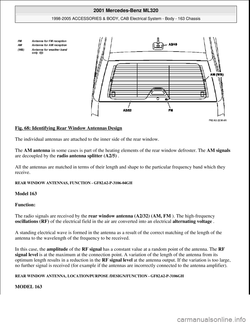
Fig. 68: Identifying Rear Window Antennas Design
The individual antennas are attached to the inner side of the rear window.
The AM antenna in some cases is part of the heating elements of the rear window defroster. The AM signals
are decoupled by the radio antenna splitter (A2/5) .
All the antennas are matched in terms of their length and shape to the particular frequency band which they
receive.
REAR WINDOW ANTENNAS, FUNCTION - GF82.62-P-3106-04GH
Model 163
Function:
The radio signals are received by the rear window antenna (A2/32) (AM, FM ). The high-frequency
oscillations (RF) of the electrical field in the air are converted into an electrical alternating voltage .
A standing electrical wave is formed in the antenna as a result of the correct matching of the length of the
antenna to the wavelength of the frequency to be received.
In this case, the amplitude of the RF signal has a constant value at a random point of the antenna. The RF
signal level is at the maximum at the connection point. A variation of the length of the antenna from its
optimum length results in a reduction in the RF signal level at the antenna output. If the variation is too large,
no further signal is received (for example if the antennas are incorrectly connected to the antenna amplifier).
REAR WINDOW ANTENNA, LOCATION/PURPOSE /DESIGN/FUNCTION - GF82.62-P-3106GH
MODEL 163
2001 Mercedes-Benz ML320
1998-2005 ACCESSORIES & BODY, CAB Electrical System - Body - 163 Chassis
me
Saturday, October 02, 2010 3:30:06 PMPage 116 © 2006 Mitchell Repair Information Company, LLC.
Page 1665 of 4133
INTERMITTENT INTERRUPTIONS OF RADIO RECEPTION IN RDS MODE - AF82.60-P-1101A
MODELS 163,168,170, 208, 210 with CODE (756a) MB radio Audio 10 RDS with CD compartment
PROBLEM WITH RADIO RECEPTION AFTER INSTALLING SUN SHIELD FILM - AF82.60-P-1105A
MODEL 163, 202, 203, 208, 209, 210, 211, 215, 220
Modification notes
Damage codeCauseRemedy
Under unfavorable
reception conditions in
FM-RDS mode, the radio
may frequently switch to
alternative frequencies of
one and the same radio
station. Due to the equipment
and antenna design there
is no remedy available.
During switchover,
reception may be
interrupted for a brief
period.Do not replace any radios
subject to this complaint
only!
11.2.00Supersedes STIP 82.60-
030 dated 10.2.00
Damage codeCauseRemedy
Complaint is caused by
retrofitting metallized
window foils. When installing
window foils, cut foil
outside of vehicle to
avoid damaging the
antennas and heating
wires
Metallized foil:
AM reception
reduced approx. 70
%, among other
problems search
stop no longer
possible
FM reception
reduced approx. 10
% .
TV reception
reduced approx. 10
Do not use metallized
foil.
Advise customer of
negative effects to
reception
2001 Mercedes-Benz ML320
1998-2005 ACCESSORIES & BODY, CAB Electrical System - Body - 163 Chassis
me
Saturday, October 02, 2010 3:30:07 PMPage 170 © 2006 Mitchell Repair Information Company, LLC.
Page 1716 of 4133
AUDIO 30 APS DIAGNOSIS, TROUBLESHOOTING - AD82.61-P-5001A
MODEL 163,168,170, 208, 210 with CODE (353) Audio 30 APS
GPS antenna
splitter (A2/57) or
lead defective
B1763Excessive
temperature or
reading error of CD
drive of radio and
navigation unit
(A2/56) Remove CD-ROM
from drive and check
for contamination
and damage. A2/56
B1765Gyrosensor defective A2/56
N1111
N1112
N1113
N1114
N1115
N1116
N1117
N1118Fiber optic cable
defective, Individual
D2B units defective
or power supply for
individual D2B unitsSee also: ?
Information/Communication Diagnosis
Manual Index 13.1 Digital data bus
(D2B)Model 168, 170,
208, 210
AD82.00-P-4000A
N1140Only on model 208,
210:
DTC in CAN
connection between
instrument cluster
(A1) and radio and
navigation unit
(A2/56) The radio and navigation unit
(A2/56) is connected to the
instrument cluster (A1)via a separate
CAN bus.
DTC memory for instrument cluster
(A1) CAN line between
A1 and A2/56
N1141Nominal-actual
configuration of D2B
ring variesSee also: ?
Information/Communication Diagnosis
Manual Index 13.1 Digital data bus
(D2B)Reconfigure system
AD82.00-P-4000A
N1250CD changer
Excess temperature Lower temperature
inside vehicle
N1251CD changer
CD reading error Check CD changer
N1252CD changer
CD magazine error Check CD magazine
N1253CD changer
Hardware error
(mechanical) Check hardware
components and
replace if necessary
N1254CD changer
Insufficient
temperature Heating passenger
compartment
2001 Mercedes-Benz ML320
1998-2005 ACCESSORIES & BODY, CAB Electrical System - Body - 163 Chassis
me
Saturday, October 02, 2010 3:30:08 PMPage 221 © 2006 Mitchell Repair Information Company, LLC.
Page 2068 of 4133
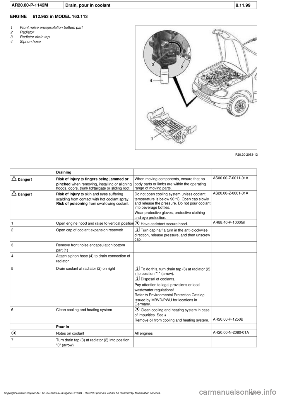
AR20.00-P-1142M
Drain, pour in coolant
8.11.99
ENGINE
612.963 in MODEL 163.113
P20.20-2083-12
1
Front noise encapsulation bottom part
2
Radiator
3
Radiator drain tap
4
Siphon hose
Draining
Danger!
Risk of injury
to
fingers being jammed or
pinched
when removing, installing or aligning
hoods, doors, trunk lid/tailgate or sliding roof.
When moving components, ensure that no
body parts or limbs are within the operating
range of moving parts.
AS00.00-Z-0011-01A
Danger!
Risk of injury
to skin and eyes suffering
scalding from contact with hot coolant spray.
Risk of poisoning
from swallowing coolant.
Do not open cooling system unless coolant
temperature is below 90 °C. Open cap slowly
and release the pressure. Do not pour coolant
into beverage bottles.
Wear protective gloves, protective clothing
and eye protection.
AS20.00-Z-0001-01A
1
Open engine hood and raise to vertical position
Have assistant secure hood.
AR88.40-P-1000GI
2
Open cap of coolant expansion reservoir
Turn cap half a turn in the anti-clockwise
direction, release pressure, and then unscrew
cap.
3
Remove front noise encapsulation bottom
part (1)
4
Attach siphon hose (4) to drain connection of
radiator
5
Drain coolant at radiator (2) on right
To do this, turn drain tap (3) at radiator (2)
into position "1" (arrow).
Disposal of coolants.
Pay attention to legal provisions or local
wastewater regulations!
Refer to Environmental Protection Catalog
issued by MBVD/PWU for locations in
Germany.
6
Clean cooling and heating system
Clean cooling and heating system in case
of impurities. See
#
Remove oil from cooling and heating system.
AR20.00-P-1250B
Pour in
Notes on coolant
All engines
AH20.00-N-2080-01A
7
Turn drain tap (3) at radiator (2) into position
"0" (arrow)
Copyright DaimlerChrysler AG 12.05.2006 CD-Ausgabe G/10/04 . This WIS print-out will not be recorde
d by Modification services.
Page 1
Page 2075 of 4133
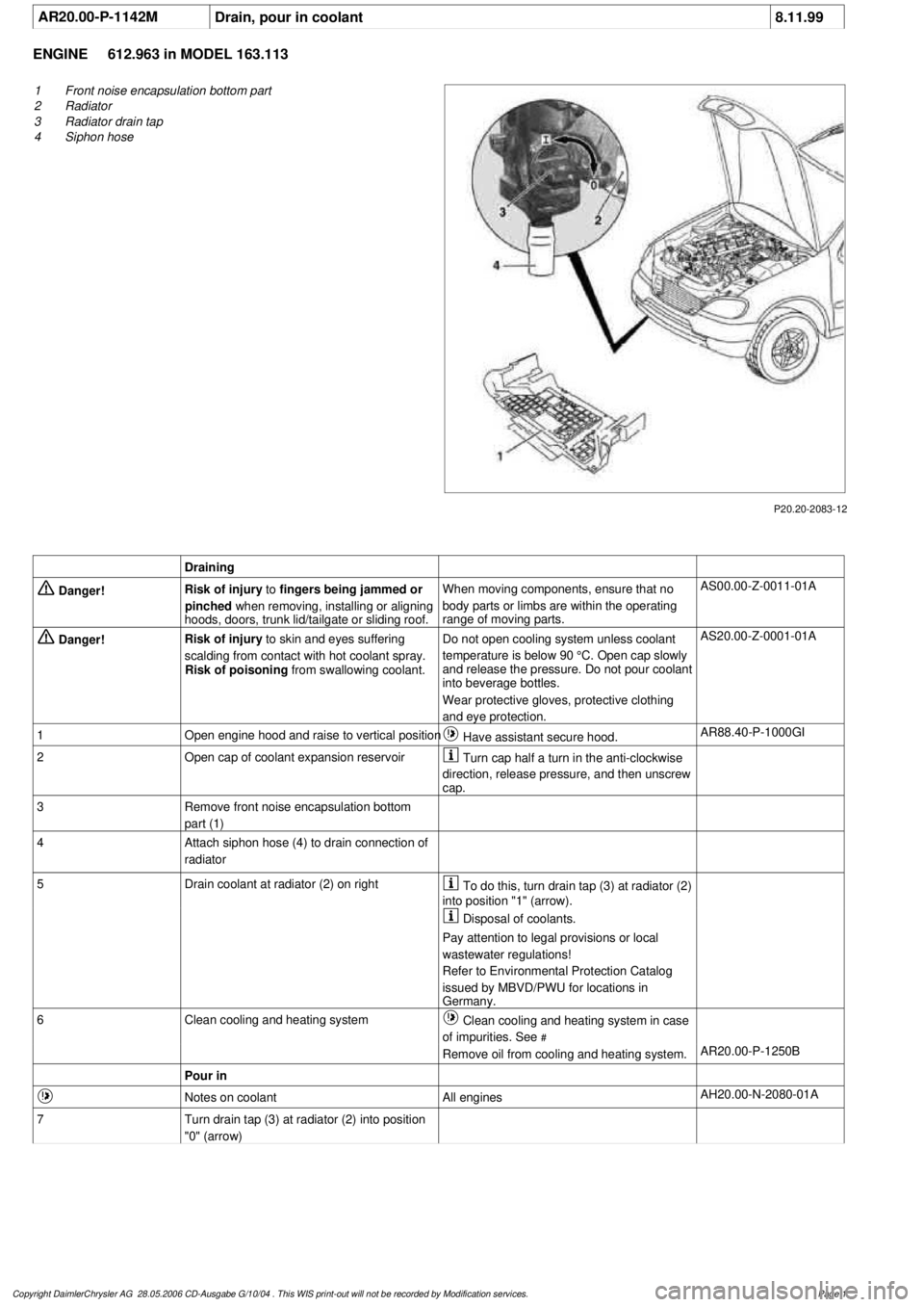
AR20.00-P-1142M
Drain, pour in coolant
8.11.99
ENGINE
612.963 in MODEL 163.113
P20.20-2083-12
1
Front noise encapsulation bottom part
2
Radiator
3
Radiator drain tap
4
Siphon hose
Draining
Danger!
Risk of injury
to
fingers being jammed or
pinched
when removing, installing or aligning
hoods, doors, trunk lid/tailgate or sliding roof.
When moving components, ensure that no
body parts or limbs are within the operating
range of moving parts.
AS00.00-Z-0011-01A
Danger!
Risk of injury
to skin and eyes suffering
scalding from contact with hot coolant spray.
Risk of poisoning
from swallowing coolant.
Do not open cooling system unless coolant
temperature is below 90 °C. Open cap slowly
and release the pressure. Do not pour coolant
into beverage bottles.
Wear protective gloves, protective clothing
and eye protection.
AS20.00-Z-0001-01A
1
Open engine hood and raise to vertical position
Have assistant secure hood.
AR88.40-P-1000GI
2
Open cap of coolant expansion reservoir
Turn cap half a turn in the anti-clockwise
direction, release pressure, and then unscrew
cap.
3
Remove front noise encapsulation bottom
part (1)
4
Attach siphon hose (4) to drain connection of
radiator
5
Drain coolant at radiator (2) on right
To do this, turn drain tap (3) at radiator (2)
into position "1" (arrow).
Disposal of coolants.
Pay attention to legal provisions or local
wastewater regulations!
Refer to Environmental Protection Catalog
issued by MBVD/PWU for locations in
Germany.
6
Clean cooling and heating system
Clean cooling and heating system in case
of impurities. See
#
Remove oil from cooling and heating system.
AR20.00-P-1250B
Pour in
Notes on coolant
All engines
AH20.00-N-2080-01A
7
Turn drain tap (3) at radiator (2) into position
"0" (arrow)
Copyright DaimlerChrysler AG 28.05.2006 CD-Ausgabe G/10/04 . This WIS print-out will not be recorde
d by Modification services.
Page 1
Page 2139 of 4133

GF54.21-P-4106-01GH
Extended Activity Module - Task
n
The primary tasks of the Extended Activity Module (EAM, N10/1) are
as follows:
D
To control the door sill lights
D
To suppress the auto-dimming mirror function
D
To control the headlight cleaning system (HCS)
D
To control the rear window defroster
D
To control seat heating
D
To control the power supply via control console to tilt/sliding or
louvered sunroof switch
D
To control the PTC heater booster (R22/3)
D
To control the auxiliary fan (M4)
D
To read the cruise control switch (S40) and relay data to control
module (DAS, N73/1)
D
To read the contacts for wiper speed settings 1 and 2 on
combination switch (S4) for diagnosis.
To perform these tasks the Extended Activity Module (EAM, N10/1)
reads various signals and switch settings directly.
The Extended Activity Module (EAM, N10/1) interfaces with other
control modules via the engine compartment CAN.
-----------------------------------------------------------------------------------------
Diagnosis
Diagnosis is performed using the Star diagnostic tool. To facilitate
this task, the Extended Activity Module (EAM, N10/1) is equipped
with its own diagnostics cable.
This cable is also used to diagnose the
All Activity Module (AAM,
N10)
and the
transfer case control module (N78)
.
The Extended Activity Module (EAM, N10/1) is linked to the All
Activity Module (AAM, N10) via the
engine compartment CAN
.
Data communication between the All Activity Module (AAM,
N10) and the Extended Activity Module (EAM, N10/1) is
assumed by the
CAN (N10 - N10/1)
when terminal 15 is off.
The CAN (N10 - N10/1)
is an independent CAN bus located
between the All Activity Module (AAM, N10) and the Extended
Activity Module (EAM, N10/1).
No other
control modules are
connected to the CAN (N10 - N10/1).
-----------------------------------------------------------------------------------------
Details:
Door sill lights
When the front interior light is on and one of the front doors is open,
or when the rear interior light is on and one of the back doors is open,
the door sill lights for the open door will illuminate.
Headlight cleaning system (HCS)
Activating a separate switch causes the EAM to send a turn-on signal
to the HCS pump relay.
EAM will send an additional turn-on signal to the HCS pump relay
only after the cleaning operation is completed and a "rest period" of
approximately 2.5 sec. has passed.
Auto-dimming mirror function
The auto-dimming mirror function is suppressed when the interior
light is on or reverse gear is engaged.
Auto-dimming suppression for the outside rearview mirror (slave) is
activated by the inside rearview mirror (master).
Heater booster/PTC air heater for diesel engines
EAM monitors system voltage and adjusts heater booster capacity to
minimize load on battery.
Rear window defroster
EAM sets maximum ON time for rear window defroster depending
on outdoor temperature and current vehicle speed.
D
Standard ON time:
10 min.
D
Outdoor temperature < 5
o
C:
Additional 5 min.
D
Speed >80 km/h:
Additional 3 min.
Seat heating
Sets maximum seat heating time.
D
Setting 1: max. 20 min.
D
Setting 2: max. 5 min.
Tilt/sliding or louvered sunroofs
Signal via AAM2 allows operation of tilt/sliding or louvered sunroofs
when ignition is on (standard mode) or off (keyless mode).
Ignition authorization via CAN
The EAM issues ignition authorization to AAM2 via the engine
compartment CAN depending on the requirements of the engine
control unit in connection with the FBM.
Copyright DaimlerChrysler AG 18.05.2006 CD-Ausgabe G/10/04 . This WIS print-out will not be recorde
d by Modification services.
Page 1
Page 2171 of 4133
Engine load
Crankshaft position sensor
Camshaft Hall sensor
Coolant temperature sensor
Intake air temperature sensor/charge air.
Coil ignition: The ME control unit interrupts at the point of ignition timing at the ground end the ignition
coil primary circuit of the ignition coil.
ECI ignition system (engine 137): The ME control unit actuates the output stages in the ECI ignition
modules.
The ignition angle can only be checked with the HHT/STAR DIAGNOSIS.
2.Ignition angle adaptation
2.1 Catalytic converter heating-up (warming-up)
The ignition angle is continuously retarded for about 20 seconds in order to more rapidly warm up the catalytic
converter to its operating temperature if:
coolant temperature at start > 15 °C and < 40 °C
Selector lever position P or N
At the same time idle speed is increased by the idle speed control.
2.2 Idle speed
To assist the idle speed control, the ignition angle can be retarded by as much as 36° crank angle or advanced by
as much as 20° crank angle.
Altering the ignition angle provides a more rapid control than altering the position of the throttle valve (idle
speed control).
2.3 Deceleration fuel shutoff
The ignition angle is briefly retarded when combustion is resumed (fuel injectors actuated) in order to prevent a
sudden increase in torque.
2.4 Intake air temperature/coolant temperature
The ignition angle is retarded under load, as a function of the intake air temperature and coolant temperature, in
order to prevent an
y knocking tendency at high intake air and coolant temperatures. The ignition angle is
2001 Mercedes-Benz ML320
1998-2005 ENGINE Electrical System - Engine - 163 Chassis
me
Saturday, October 02, 2010 3:18:54 PMPage 17 © 2006 Mitchell Repair Information Company, LLC.
Page 2174 of 4133
location/design/function113, 119, 137
Engine 120GF30.20-P-3010F
Anti-knock control function GF15.12-P-4024F
Transmission overload protection
functionwith automatic
transmissionGF07.61-P-4026F
Overheating/pinging protection
function GF07.61-P-4027F
Intake air temperature correction
function GF07.61-P-4028F
ME-SFI synchronizing fuel
injection and firing order function GF07.61-P-4009F
ME-SFI ignition system signal
assignmentEngine 104GF15.12-P-0001-02D
Engine 111GF15.12-P-0001-02G
Engine 112GF15.12-P-0001-02A
Engine 113GF15.12-P-0001-02B
Engine 119GF15.12-P-0001-02E
Engine 120GF15.12-P-0001-02F
Engine 137GF15.12-P-0001-02L
ME engine speed signal function GF07.61-P-3017F
ASR V control unit
location/task/design/functionwith code 471a
Model 129, 140, 202 as
of 6/94, 170, 208, 210GF42.40-P-4500A
ESP control unit location / task /
functionwith code 472a
Model 129 with engines
104, 119, 120
Model 140
Model 210 with engine
119GF42.45-P-4500A
with code 472a
Model 129 with engine
112, 113
Model 163 up to 8/02,
168, 215
Model 220 (except
220.08/18)
Model 202, 208 with
engine 112, 113
Model 210 with engine
111, 112, 113GF42.45-P-4500B
with code 472a
Model 170 with engines
111, 112
Model 202, 208 with
Engine 111
Model 203GF42.45-P-4500C
2001 Mercedes-Benz ML320
1998-2005 ENGINE Electrical System - Engine - 163 Chassis
me
Saturday, October 02, 2010 3:18:54 PMPage 20 © 2006 Mitchell Repair Information Company, LLC.
Page 2291 of 4133
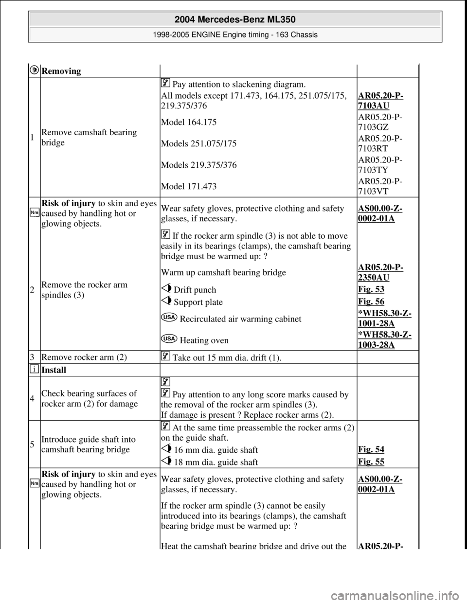
Removing
1Remove camsha ft bearing
bridge
Pay attention to slackening diagram.
All models except 171.473, 164.175, 251.075/175,
219.375/376AR05.20-P-
7103AU
Model 164.175AR05.20-P-
7103GZ
Models 251.075/175AR05.20-P-
7103RT
Models 219.375/376AR05.20-P-
7103TY
Model 171.473AR05.20-P-
7103VT
Risk of injury to skin and eyes
caused by handling hot or
glowing objects.Wear safety gloves, protec tive clothing and safety
glasses, if necessary.AS00.00-Z-
0002-01A
2Remove the rocker arm
spindles (3)
If the rocker arm spindle (3) is not able to move
easily in its bearings (clamps), the camshaft bearing
bridge must be warmed up: ?
Warm up camshaft bearing bridgeAR05.20-P-
2350AU
Drift punchFig. 53
Support plateFig. 56
Recirculated ai r warming cabinet*WH58.30-Z-
1001-28A
Heating oven*WH58.30-Z-
1003-28A
3Remove rocker arm (2) Take out 15 mm dia. drift (1).
Install
4Check bearing surfaces of
rocker arm (2) for damage
Pay attention to any l ong score marks caused by
the removal of the rocker arm spindles (3).
If damage is present ? Replace rocker arms (2).
5Introduce guide shaft into
camshaft bearing bridge
At the same time preassemble the rocker arms (2)
on the guide shaft.
16 mm dia. guide shaftFig. 54
18 mm dia. guide shaftFig. 55
Risk of injury to skin and eyes
caused by handling hot or
glowing objects.Wear safety gloves, protec tive clothing and safety
glasses, if necessary.AS00.00-Z-
0002-01A
If the rocker arm spindle (3) cannot be easily
introduced into its bearings (clamps), the camshaft
bearing bridge must be warmed up: ?
Heat the camshaft bearing bridge and drive out the AR05.20-P-
2004 Mercedes-Benz ML350
1998-2005 ENGINE Engine timing - 163 Chassis
me
Saturday, October 02, 2010 3:39:38 PMPage 50 © 2006 Mitchell Repair Information Company, LLC.