heating MERCEDES-BENZ ML500 1997 Complete Manual PDF
[x] Cancel search | Manufacturer: MERCEDES-BENZ, Model Year: 1997, Model line: ML500, Model: MERCEDES-BENZ ML500 1997Pages: 4133, PDF Size: 88.89 MB
Page 3286 of 4133
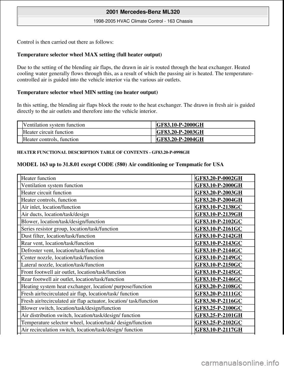
Control is then carried out there as follows:
Temperature selector wheel MAX setting (full heater output)
Due to the setting of the blending air flaps, the drawn in air is routed through the heat exchanger. Heated
cooling water generally flows through this, as a result of which the passing air is heated. The temperature-
controlled air is guided into the vehicle interior via the various air outlets.
Temperature selector wheel MIN setting (no heater output)
In this setting, the blending air flaps block the route to the heat exchanger. The drawn in fresh air is guided
directly to the air outlets and therefore into the vehicle interior.
HEATER FUNCTIONAL DESCRIPTION TABLE OF CONTENTS - GF83.20-P-0998GH
MODEL 163 up to 31.8.01 except CODE (580) Air conditioning or Tempmatic for USA
Ventilation system function GF83.10-P-2000GH
Heater circuit function GF83.20-P-2003GH
Heater controls, function GF83.20-P-2004GH
Heater function GF83.20-P-0002GH
Ventilation system function GF83.10-P-2000GH
Heater circuit function GF83.20-P-2003GH
Heater controls, function GF83.20-P-2004GH
Air inlet, location/function GF83.10-P-2138GC
Air ducts, location/task/design GF83.10-P-2139GH
Blower, location/task/design/function GF83.10-P-2102GC
Series resistor group, location/task/function GF83.10-P-2161GC
Dust filter, location/task/function GF83.10-P-2142GH
Rear vent, location/task/function GF83.10-P-2143GC
Defroster vent, location/task/function GF83.10-P-2144GC
Center nozzle, location/task/function GF83.10-P-2149GC
Lateral nozzle, location/task/function GF83.10-P-2150GC
Front footwell air outlet, location/task/function GF83.10-P-2145GC
Rear footwell air outlet, location/task/function GF83.10-P-2146GC
Heating system heat exchanger, location/ purpose/function GF83.20-P-2108GC
Fresh air/recirculated air flap, location/task/ function GF83.20-P-2111GC
Fresh air/recirculated air flap actuator, location/ task/function GF83.30-P-2116GC
Blower switch, location/task/design/function GF83.25-P-2100GC
Air distribution switch, location/task/design/ function GF83.25-P-2101GH
Temperature selector wheel, location/task/ design/function GF83.25-P-2102GC
Air recirculation switch, location/task/design/ function GF83.10-P-2117GH
2001 Mercedes-Benz ML320
1998-2005 HVAC Climate Control - 163 Chassis
me
Saturday, October 02, 2010 3:23:15 PMPage 42 © 2006 Mitchell Repair Information Company, LLC.
Page 3287 of 4133
HEATER CIRCUIT FUNCTION - GF83.20-P-2003GH
MODEL 163
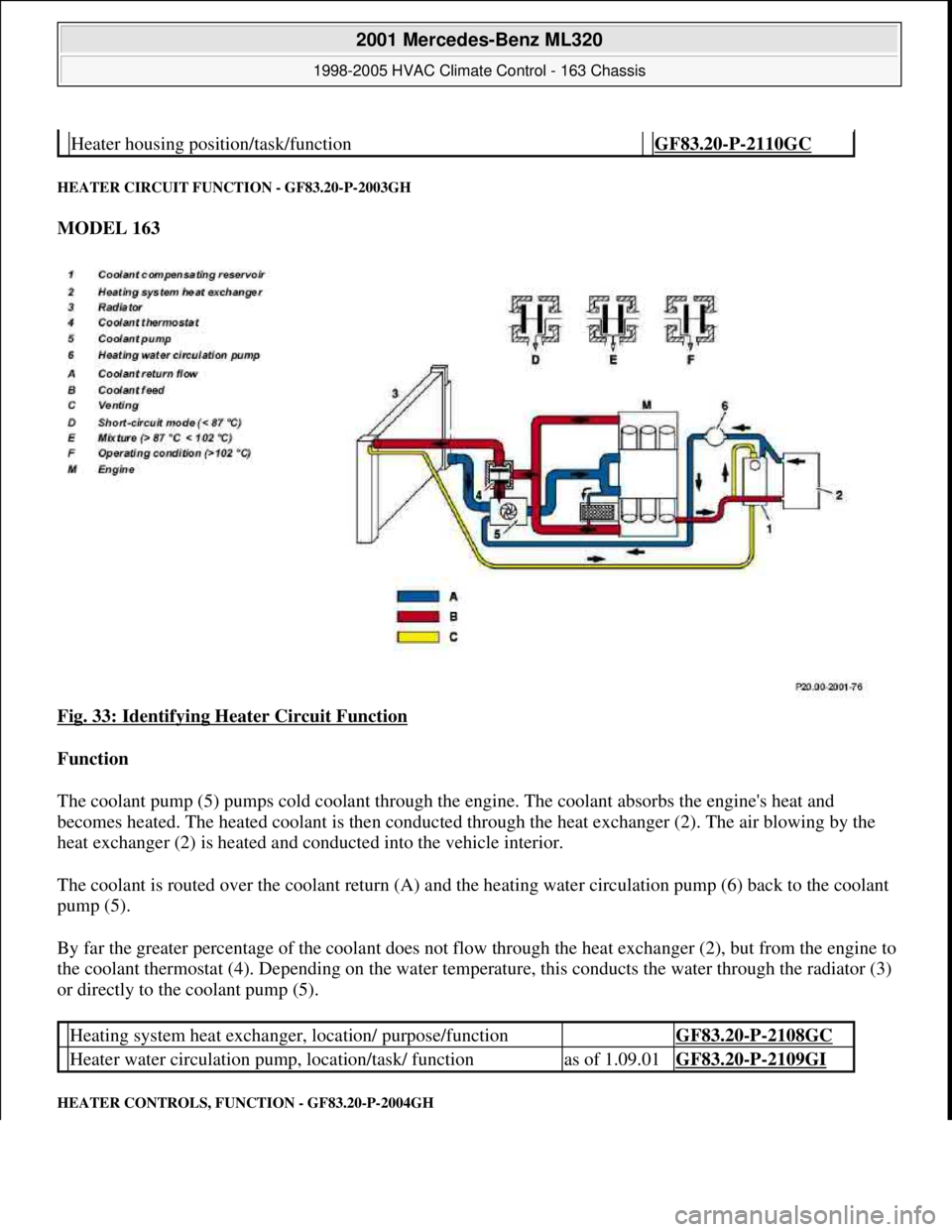
Fig. 33: Identifying Heater Circuit Function
Function
The coolant pump (5) pumps cold coolant through the engine. The coolant absorbs the engine's heat and
becomes heated. The heated coolant is then conducted through the heat exchanger (2). The air blowing by the
heat exchanger (2) is heated and conducted into the vehicle interior.
The coolant is routed over the coolant return (A) and the heating water circulation pump (6) back to the coolant
pump (5).
By far the greater percentage of the coolant does not flow through the heat exchanger (2), but from the engine to
the coolant thermostat (4). Depending on the water temperature, this conducts the water through the radiator (3)
or directly to the coolant pump (5).
HEATER CONTROLS, FUNCTION - GF83.20-P-2004GH
Heater housing position/task/function GF83.20-P-2110GC
Heating system heat exchanger, location/ purpose/function GF83.20-P-2108GC
Heater water circulation pump, location/task/ functionas of 1.09.01GF83.20-P-2109GI
2001 Mercedes-Benz ML320
1998-2005 HVAC Climate Control - 163 Chassis
me
Saturday, October 02, 2010 3:23:15 PMPage 43 © 2006 Mitchell Repair Information Company, LLC.
Page 3288 of 4133
Model 163 up to 31.8.01
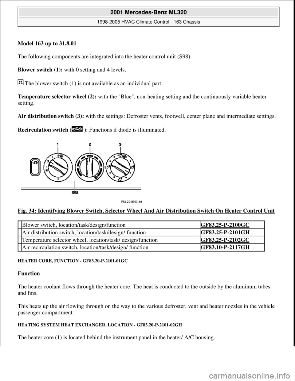
The following components are integrated into the heater control unit (S98):
Blower switch (1): with 0 setting and 4 levels.
The blower switch (1) is not available as an individual part.
Temperature selector wheel (2): with the "Blue", non-heating setting and the continuously variable heater
setting.
Air distribution switch (3): with the settings: Defroster vents, footwe ll, center plane and intermediate settings.
Recirculation switch ( ): Functions if diode is illuminated.
Fig. 34: Identifying Blower Switch, Selector Wheel And Air Distribution Switch On Heater Control Unit
HEATER CORE, FUNCTI ON - GF83.20-P-2101-01GC
Function
The heater coolant flows through the heater core. The he at is conducted to the outside by the aluminum tubes
and fins.
This heats up the air flowing through on the way to the vari ous defroster, vent and heater nozzles in the vehicle
passenger compartment.
HEATING SYSTEM HEAT EXCHANGE R, LOCATION - GF83.20-P-2101-02GH
The heater core (1) is located behind the instrument panel in the heater/ A/C housing.
Blower switch, location/task/design/function GF83.25-P-2100GC
Air distribution switch, locat ion/task/design/ function GF83.25-P-2101GH
Temperature selector wheel, location/task/ design/function GF83.25-P-2102GC
Air recirculation switch, loca tion/task/design/ function GF83.10-P-2117GH
2001 Mercedes-Benz ML320
1998-2005 HVAC Climate Control - 163 Chassis
me
Saturday, October 02, 2010 3:23:15 PMPage 44 © 2006 Mitchell Repair Information Company, LLC.
Page 3289 of 4133
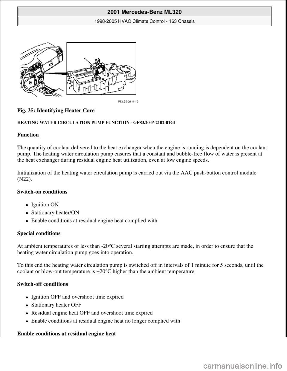
Fig. 35: Identifying Heater Core
HEATING WATER CIRCULATION PUMP FUNCTION - GF83.20-P-2102-01GI
Function
The quantity of coolant delivered to the heat exchanger when the engine is running is dependent on the coolant
pump. The heating water circulation pump ensures that a constant and bubble-free flow of water is present at
the heat exchanger during residual engine heat utilization, even at low engine speeds.
Initialization of the heating water circulation pump is carried out via the AAC push-button control module
(N22).
Switch-on conditions
Ignition ON
Stationary heater/ON
Enable conditions at residual engine heat complied with
Special conditions
At ambient temperatures of less than -20°C several starting attempts are made, in order to ensure that the
heating water circulation pump goes into operation.
To this end the heating water circulation pump is switched off in intervals of 1 minute for 5 seconds, until the
coolant or blow-out temperature is +20°C higher than the ambient temperature.
Switch-off conditions
Ignition OFF and overshoot time expired
Stationary heater OFF
Residual engine heat OFF and overshoot time expired
Enable conditions at residual engine heat no longer complied with
Enable conditions at residual engine heat
2001 Mercedes-Benz ML320
1998-2005 HVAC Climate Control - 163 Chassis
me
Saturday, October 02, 2010 3:23:15 PMPage 45 © 2006 Mitchell Repair Information Company, LLC.
Page 3290 of 4133
The heating water circulation pump runs in any event 1 minute after starting residual engine heat operation. The
overshoot conditions at least will be fulfilled.
Overshoot conditions
Coolant temperature 100°C --> overshoot time 5 minutes
Coolant temperature >100°C --> overshoot time 10 minutes
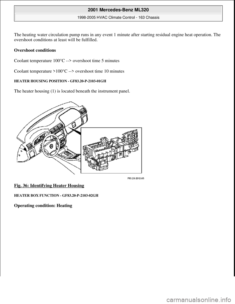
HEATER HOUSING POSITION - GF83.20-P-2103-01GH
The heater housing (1) is located beneath the instrument panel.
Fig. 36: Identifying Heater Housing
HEATER BOX FUNCTION - GF83.20-P-2103-02GH
Operating condition: Heating
2001 Mercedes-Benz ML320
1998-2005 HVAC Climate Control - 163 Chassis
me
Saturday, October 02, 2010 3:23:15 PMPage 46 © 2006 Mitchell Repair Information Company, LLC.
Page 3291 of 4133
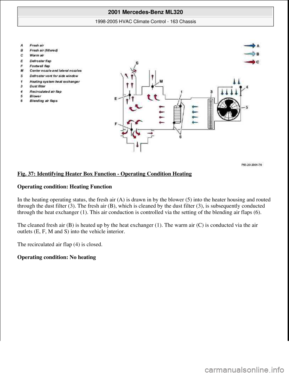
Fig. 37: Identifying Heater Box Function - Operating Condition Heating
Operating condition: Heating Function
In the heating operating status, the fresh air (A) is drawn in by the blower (5) into the heater housing and routed
through the dust filter (3). The fresh air (B), which is cleaned by the dust filter (3), is subsequently conducted
through the heat exchanger (1). This air conduction is controlled via the setting of the blending air flaps (6).
The cleaned fresh air (B) is heated up by the heat exchanger (1). The warm air (C) is conducted via the air
outlets (E, F, M and S) into the vehicle interior.
The recirculated air flap (4) is closed.
Operating condition: No heating
2001 Mercedes-Benz ML320
1998-2005 HVAC Climate Control - 163 Chassis
me
Saturday, October 02, 2010 3:23:15 PMPage 47 © 2006 Mitchell Repair Information Company, LLC.
Page 3292 of 4133
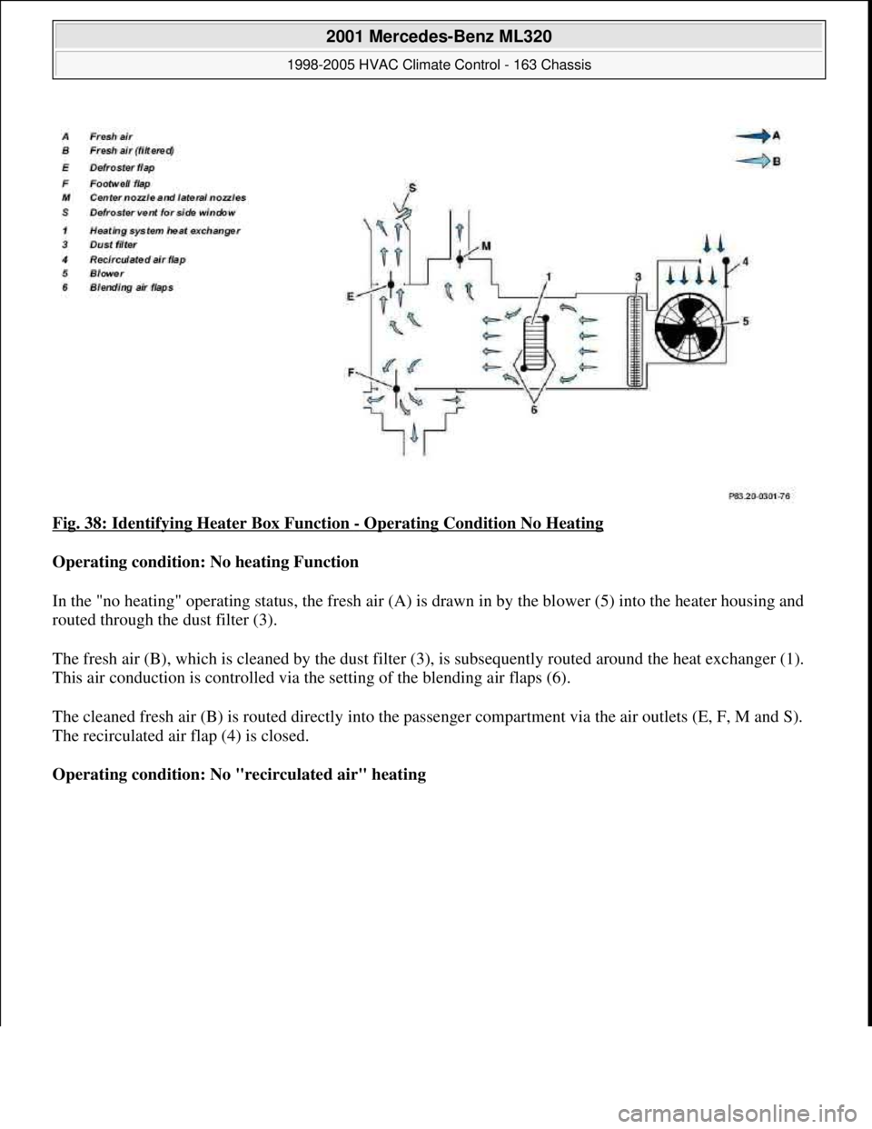
Fig. 38: Identifying Heater Box Function - Operating Condition No Heating
Operating condition: No heating Function
In the "no heating" operating status, the fresh air (A) is drawn in by the blower (5) into the heater housing and
routed through the dust filter (3).
The fresh air (B), which is cleaned by the dust filter (3), is subsequently routed around the heat exchanger (1).
This air conduction is controlled via the setting of the blending air flaps (6).
The cleaned fresh air (B) is routed directly into the passenger compartment via the air outlets (E, F, M and S).
The recirculated air flap (4) is closed.
Operating condition: No "recirculated air" heating
2001 Mercedes-Benz ML320
1998-2005 HVAC Climate Control - 163 Chassis
me
Saturday, October 02, 2010 3:23:15 PMPage 48 © 2006 Mitchell Repair Information Company, LLC.
Page 3293 of 4133
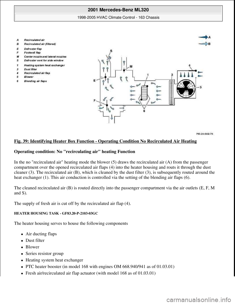
Fig. 39: Identifying Heater Box Function - Operating Condition No Recirculated Air Heating
Operating condition: No "recirculating air" heating Function
In the no "recirculated air" heating mode the blower (5) draws the recirculated air (A) from the passenger
compartment over the opened recirculated air flaps (4) into the heater housing and routs it through the dust
cleaner (3). The recirculated air (B), which is cleaned by the dust filter (3), is subsequently routed around the
heat exchanger (1). This air conduction is controlled via the setting of the blending air flaps (6).
The cleaned recirculated air (B) is routed directly into the passenger compartment via the air outlets (E, F, M
and S).
The supply of fresh air is cut off by the recirculated air flap (4).
HEATER HOUSING TASK - GF83.20-P-2103-03GC
The heater housing serves to house the following components
Air ducting flaps
Dust filter
Blower
Series resistor group
Heating system heat exchanger
PTC heater booster (in model 168 with engines OM 668.940/941 as of 01.03.01)
Fresh air/recirculated air flap actuator (with model 168 as of 01.03.01)
2001 Mercedes-Benz ML320
1998-2005 HVAC Climate Control - 163 Chassis
me
Saturday, October 02, 2010 3:23:15 PMPage 49 © 2006 Mitchell Repair Information Company, LLC.
Page 3294 of 4133
and therefore forms a complete unit.
The heater housing distributes the air which is required to ventilate the vehicle interior to the relevant air ducts
and air outlets depending on the temperature desired in the interior.
The air ducting depends on various operating conditions such as:
Heating
No heating
Fresh air mode
Recirculated air mode
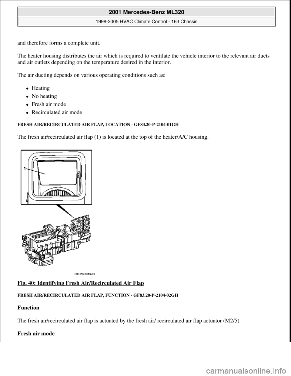
FRESH AIR/RECIRCULATED AIR FLAP, LOCATION - GF83.20-P-2104-01GH
The fresh air/recirculated air flap (1) is located at the top of the heater/A/C housing.
Fig. 40: Identifying Fresh Air/Recirculated Air Flap
FRESH AIR/RECIRCULATED AIR FLAP, FUNCTION - GF83.20-P-2104-02GH
Function
The fresh air/recirculated air flap is actuated by the fresh air/ recirculated air flap actuator (M2/5).
Fresh air mode
2001 Mercedes-Benz ML320
1998-2005 HVAC Climate Control - 163 Chassis
me
Saturday, October 02, 2010 3:23:15 PMPage 50 © 2006 Mitchell Repair Information Company, LLC.
Page 3295 of 4133
The fresh air/recirculated air flap shuts off the supply of recirculated air.
Fresh air is drawn in.
Recirculation mode
The fresh air/recirculated air flap shuts off the supply of fresh air. Air is drawn in from the passenger
compartment.
HEATER CORE, LOCATION/PURPOSE/FUNCTION - GF83.20-P-2108GC
MODEL 163, 168
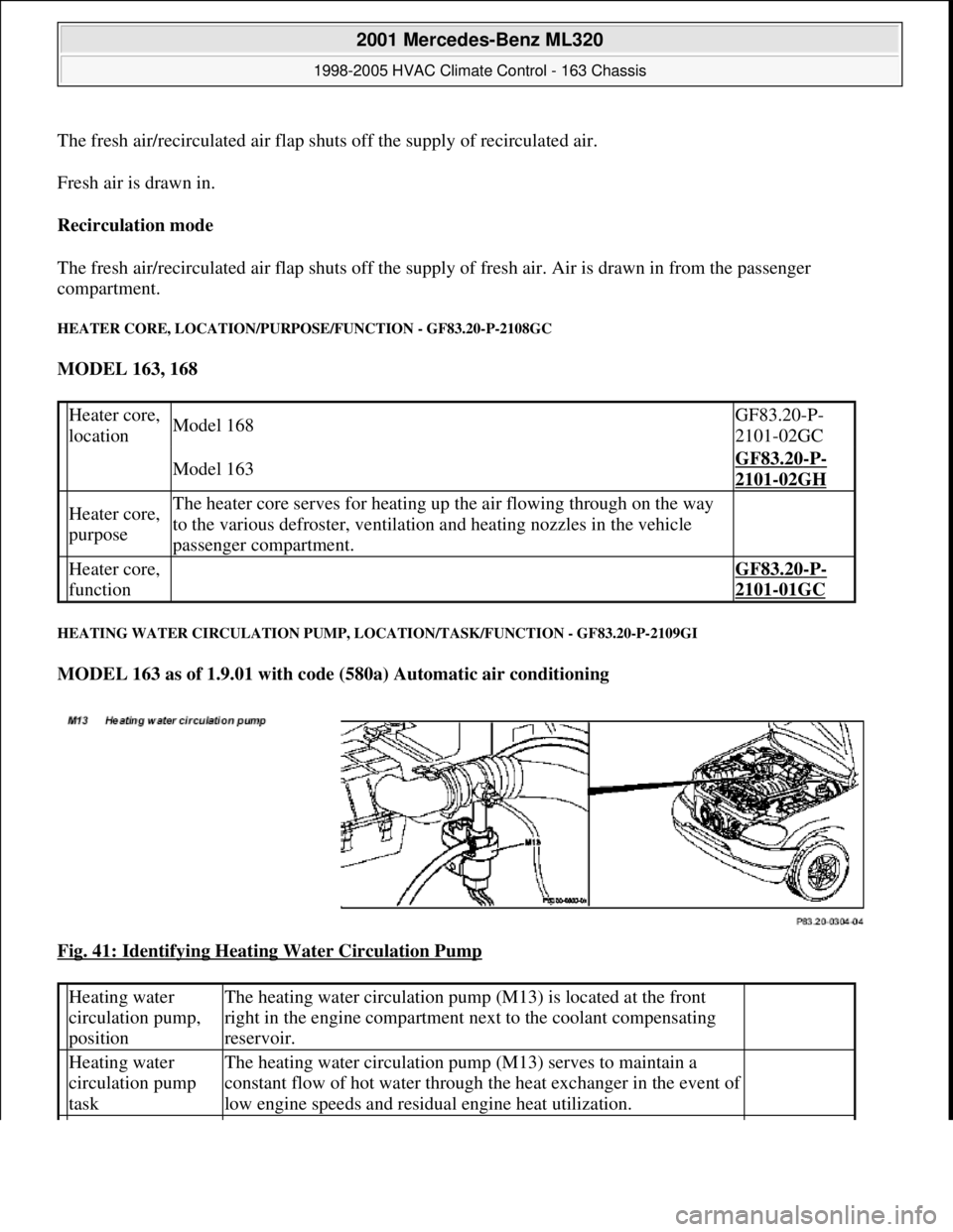
HEATING WATER CIRCULATION PUMP, LOCATION/TASK/FUNCTION - GF83.20-P-2109GI
MODEL 163 as of 1.9.01 with code (580a) Automatic air conditioning
Fig. 41: Identifying Heating Water Circulation Pump
Heater core,
locationModel 168GF83.20-P-
2101-02GC
Model 163GF83.20-P-
2101-02GH
Heater core,
purposeThe heater core serves for heating up the air flowing through on the way
to the various defroster, ventilation and heating nozzles in the vehicle
passenger compartment.
Heater core,
function GF83.20-P-
2101-01GC
Heating water
circulation pump,
positionThe heating water circulation pump (M13) is located at the front
right in the engine compartment next to the coolant compensating
reservoir.
Heating water
circulation pump
taskThe heating water circulation pump (M13) serves to maintain a
constant flow of hot water through the heat exchanger in the event of
low engine speeds and residual engine heat utilization.
2001 Mercedes-Benz ML320
1998-2005 HVAC Climate Control - 163 Chassis
me
Saturday, October 02, 2010 3:23:15 PMPage 51 © 2006 Mitchell Repair Information Company, LLC.