MERCEDES-BENZ S-Class 2013 W221 Owner's Manual
Manufacturer: MERCEDES-BENZ, Model Year: 2013, Model line: S-Class, Model: MERCEDES-BENZ S-Class 2013 W221Pages: 542, PDF Size: 7.97 MB
Page 491 of 542

X
Secure the vehicle by applying the electri cparking brake.
X Shift the transmission to position P.
X Switch off all electrical consumers (e.g. radio, blower, etc.).
X Open the hood (Y page 462). Positio
nnumber 0023identifies the charged battery of the other vehicle or an equivalen tjump-
starting device.
X Remove the cover from positive terminal 0002.
X Connect positive terminal 0002on your vehicle to positive terminal 0003of donor battery 0023
using the jumper cable, beginning with your own battery.
X Start the engine of th edonor vehicle and run it at idling speed.
X Connect negative terminal 0026of donor battery 0023to ground point 0025of your vehicle using
the jumper cable, connecting the jumper cable to donor battery 0023first.
X Start the engine.
X Before disconnecting the jumper cables, let the engine run for several minutes.
X First remove the jumper cables from ground point 0025and negative terminal 0026, then from
positive terminal 0002and positive terminal 0003, each time disconnecting from the battery on
your own vehicle first.
X Have the battery checked at a qualified specialist workshop.
i Jump-starting is not considered to be a normal operating condition.
i Jumper cables and further information regarding jump starting can be obtained at any
qualified specialist workshop. Jump-starting
489Breakdown assistance Z
Page 492 of 542
Towing and tow-starting
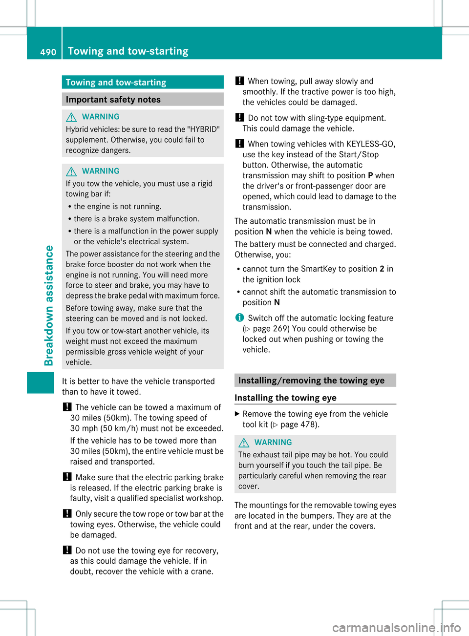
Important safety notes
G
WARNING
Hybrid vehicles: be sure to read the "HYBRID"
supplement. Otherwise, you could fail to
recognize dangers. G
WARNING
If you tow the vehicle, you must use a rigid
towing ba rif:
R the engine is not running.
R there is a brake system malfunction.
R there is a malfunction in the power supply
or the vehicle's electrical system.
The power assistance for the steering and the
brake force booster do not work when the
engine is not running. You will need more
force to steer and brake, you may have to
depress the brake pedal with maximu mforce.
Before towing away, make sure that the
steering can be moved and is not locked.
If you tow or tow-start another vehicle, its
weight must not exceed the maximum
permissible gross vehicle weight of your
vehicle.
It is better to have the vehicle transported
than to have it towed.
! The vehicle can be towed a maximum of
30 miles (50km). The towing speed of
30 mph (50 km/h) must not be exceeded.
If the vehicle has to be towed more than
30 miles (50km), the entire vehicle must be
raised and transported.
! Make sure that the electric parking brake
is released. If the electric parking brake is
faulty, visit a qualified specialist workshop.
! Only secure the tow rope or tow bar at the
towing eyes. Otherwise, the vehicle could
be damaged.
! Do not use the towing eye for recovery,
as this could damage the vehicle. If in
doubt, recover the vehicle with a crane. !
When towing, pull away slowly and
smoothly. If the tractive power is too high,
the vehicles could be damaged.
! Do not tow with sling-type equipment.
This could damage the vehicle.
! When towing vehicles with KEYLESS-GO,
use the key instead of the Start/Stop
button. Otherwise, the automatic
transmission may shift to position Pwhen
the driver's or front-passenger door are
opened, which could lead to damage to the
transmission.
The automatic transmission must be in
position Nwhen the vehicle is being towed.
The battery must be connected and charged.
Otherwise, you:
R cannot turn the SmartKey to position 2in
the ignition lock
R cannot shift the automatic transmission to
position N
i Switch off the automatic locking feature
(Y page 269) You could otherwise be
locked out when pushing or towing the
vehicle. Installing/removing the towing eye
Installing the towing eye X
Remove the towing eye from the vehicle
tool kit (Y page 478). G
WARNING
The exhaust tail pipe may be hot. You could
burn yourself if you touch the tail pipe. Be
particularly careful when removing the rear
cover.
The mountings for the removable towing eyes
are located in the bumpers. They are at the
front and at the rear, under the covers. 490
Towing and tow-startingBreakdown assistance
Page 493 of 542

X
Press the mark on cover 0002inwards in the
direction of the arrow.
X Take cover 0002off the opening.
X Screw the towing eye in clockwise to the
stop and tighten it.
Removing the towing eye X
Loosen the towing eye and unscrew it.
X Attach cover 0002to the bumper and press
until it engages.
X Place the towing eye in the vehicle tool kit. Towing the vehicle with the rear axle
raised
Only possible on vehicles without
4MATIC.
When towing your vehicle with the rear axle
raised, it is importan tthat you observe the
safety instructions (Y page 490).
! The ignition must be switched off if you
are towing the vehicle with the rear axle
raised. Intervention by ESP ®
could
otherwise damage the brake system. X
Switch on the hazard warning lamps
(Y page 283).
X Turn the SmartKey to position 0in the
ignition lock and remove the SmartKey
from the ignition lock.
X When leaving the vehicle, take the
SmartKey or the KEYLESS-GO key with you. Towing
avehicle with both axles on
the ground
When having your vehicle towed, observe the
important safety notes (Y page 490). G
WARNING
The power assistance for the steering and the
brake force booster do not work when the
engine is not running. You will then need
much more effort to brake and steer the
vehicle .Adapt your style of driving
accordingly.
The automatic transmission automatically
shifts to position Pwhen you open the driver's
or front-passenger door or when you remove
the SmartKey from the ignition lock. In order
to ensure that the automatic transmission
stays in position Nwhen towing the vehicle,
you must observe the following points:
X Make sure that the vehicle is stationary and
the SmartKey in the ignition lock is in
position 0.
X Turn the SmartKey to position 2in the
ignition lock.
On vehicles with KEYLESS-GO, use the key
instead of the Start/Stop button
(Y page 307).
X Depress and hold the brake pedal.
X Shift the automatic transmission to
position N.
X Release the brake pedal.
X Release the electric parking brake. Towing and tow-starting
491Breakdown assistance Z
Page 494 of 542
X
Switch on the hazard warning lamps
(Y page 283).
X Leave the SmartKey in position 2in the
ignition lock.
i Whe ntowing with the hazard warning
lamps switched on, use the combination
switch as usual to signal a change of
direction .Inthis case, only the turn signals
for the desired direction flash. When the
combination switch is reset, the hazard
warning lamps start flashing again. Transporting the vehicle
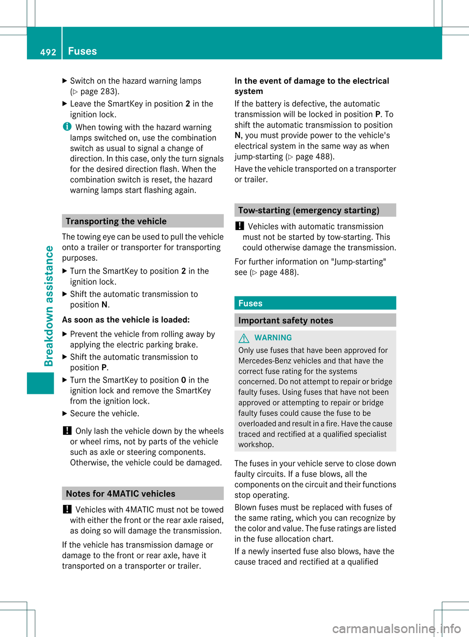
The towing eye can be used to pull the vehicle
onto a trailer or transporter for transporting
purposes.
X Turn the SmartKey to position 2in the
ignition lock.
X Shift the automatic transmission to
position N.
As soon as the vehicle is loaded:
X Prevent the vehicle from rolling away by
applying the electric parking brake.
X Shift the automatic transmission to
position P.
X Turn the SmartKey to position 0in the
ignition lock and remove the SmartKey
from the ignition lock.
X Secure the vehicle.
! Only lash the vehicle down by the wheels
or wheel rims, not by parts of the vehicle
such as axle or steering components.
Otherwise, the vehicle could be damaged. Notes for 4MATIC vehicles
! Vehicles with 4MATIC must not be towed
with either the front or the rear axle raised,
as doing so will damage the transmission.
If the vehicle has transmission damage or
damage to the front or rear axle, have it
transported on a transporter or trailer. In the event of damage to the electrical
system
If the battery is defective, the automatic
transmission will be locked in position
P. To
shift the automatic transmission to position
N, you must provide power to the vehicle's
electrical system in the same way as when
jump-starting (Y page 488).
Have the vehicle transported on a transporter
or trailer. Tow-starting (emergency starting)
! Vehicles with automatic transmission
must not be started by tow-starting. This
could otherwise damage the transmission.
For further information on "Jump-starting"
see (Y page 488). Fuses
Important safety notes
G
WARNING
Only use fuses that have been approved for
Mercedes-Ben zvehicles and that have the
correct fuse rating for the systems
concerned. Do not attempt to repair or bridge
faulty fuses. Using fuses that have not been
approved or attempting to repair or bridge
faulty fuses could cause the fuse to be
overloaded and result in afire. Have the cause
traced and rectified at a qualified specialist
workshop.
The fuses in your vehicle serve to close down
faulty circuits. If afuse blows, all the
components on the circuit and their functions
stop operating.
Blown fuses must be replace dwith fuses of
the same rating, which you can recognize by
the color and value. The fuse ratings are listed
in the fuse allocation chart.
If a newly inserted fuse also blows, have the
cause traced and rectified at a qualified 492
FusesBreakdown assistance
Page 495 of 542

specialist workshop, e.g. an authorized
Mercedes-Benz Center.
!
Only use fuses that have been approved
for Mercedes-Benz vehicles and which
have the correct fuse rating for the system
concerned. Otherwise, components or
systems could be damaged. Before changing a fuse
X Secure the vehicle against rolling away
(Y page 327).
X Switch off all electrical consumers.
X Remove the SmartKey from the ignition
lock.
The fuses are located in various fuse boxes:
R Fuse box on the right and left-hand sides of
the dashboard
R Fuse box in the rear
R Fuse box in the engine compartment on the
left-hand side of the vehicle, when viewed
in the direction of travel
R Fuse box in the engine compartment on the
right-hand side of the vehicle, when viewed
in the direction of travel
The fuse allocation chart is in the vehicle
document wallet. Dashboard fuse box
There is a fuse box located on both the
driver's side and the front-passenger side.
! Do not use a pointed object such as a
screwdriver to open the cover in the
dashboard. You could damage the
dashboard or the cover. Driver's side illustrated
X
To open: pull cover 0002outwards in the
direction of the arrow and remove it.
X To close: clip in cover 0002on the front of
the dashboard.
X Fold cover 0002inwards until it engages. Fuse box in the rear
The fuse box is behind the armrest in the rear. X
To open: fold down the armrest.
X Pull handle 0002on the trim behind the rear
seat armrest up in the direction of the
arrow.
X Fold down trim 0003. Fuses
493Breakdown assistance Z
Page 496 of 542

X
Loosen cover 0025with a suitable object 0026.
X Remove cover 0025upwards in the direction
of the arrow.
! The cover must be seated properly,
otherwise moisture or dirt could impair the
function of the fuses. Fuse box in the engine compartment
Fuse box on the left in the direction of
travel X
Open the hood (Y page 462).X
Remove any existing moisture from the
fuse box using a dry cloth.
X AMG vehicles: remove the control unit
above the fuse box.
X To open: undo screws 0002with an Allen
key.
X Remove bracket 0026.
X Remove cover 0003. X
To close: check whether the rubber seal is
lying correctly in cover 0003.
X Put cover 0003back in position.
X Replace bracket 0026.
X Tighten screws 0002using an Allen key.
! The cover must be seated properly,
otherwise moisture or dirt could impair the
function of the fuses.
X Close the hood (Y page 463).
Fuse box on the right in the direction of
travel X
Open the hood (Y page 462). X
Remove any existing moisture from the
fuse box using a dry cloth.
X To open: open clamps 0003.
X Remove cover 0003upwards.
X To close: check whether the rubber seal is
lying correctly in cover 0003.
X Put cover 0003back in position.
X Fold down cover 0002and close clamps 0003.
! The cover must be seated properly,
otherwise moisture or dirt could impair the
function of the fuses.
X Close the hood (Y page 463).494
FusesBreakdown assistance
Page 497 of 542
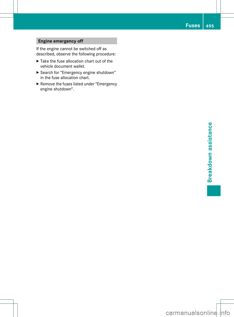
Engine emergency off
If the engine cannot be switched off as
described, observe the followin gprocedure:
X Take the fuse allocation chart out of the
vehicle document wallet.
X Search for “Emergency engine shutdown”
in the fuse allocation chart.
X Remove the fuses listed under "Emergency
engine shutdown". Fuses
495Breakdown assistance Z
Page 498 of 542
496
Page 499 of 542
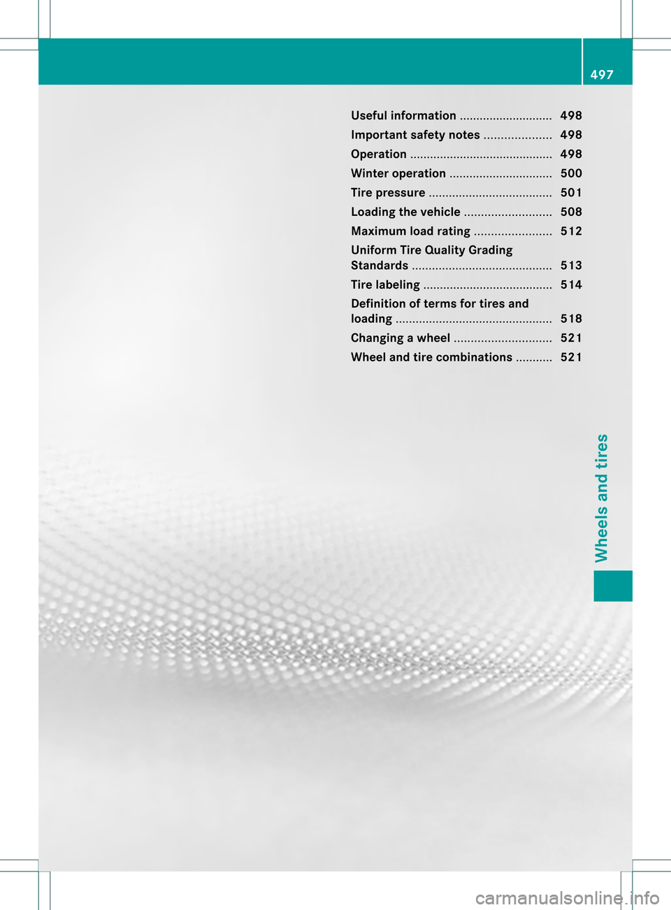
Useful information
............................498
Important safety notes ....................498
Operation ........................................... 498
Winter operation ............................... 500
Tire pressure ..................................... 501
Loading the vehicle ..........................508
Maximum load rating .......................512
Uniform Tire Quality Grading
Standards .......................................... 513
Tire labeling ....................................... 514
Definition of terms for tires and
loading ............................................... 518
Changing awheel ............................. 521
Wheel and tire combinations ...........521 497Wheels and tires
Page 500 of 542
Useful information
i This Operator's Manual describes all
models and all standard and optional
equipment of your vehicle available at the
time of publication of the Operator's
Manual. Country-specific differences are
possible. Please note that your vehicle may
not be equipped with all features
described. This also applies to safety-
related systems and functions.
i Please read the information on qualified
specialist workshops (Y page 31).Important safety notes
G
WARNING
If wheels and tires of the wrong size are used,
the wheel brakes or suspension components
may be damaged. There is arisk of accident.
Always replace wheels and tires with those
that fulfill the specifications of the original
part (designation, manufacturer, model). G
WARNING
Af lat tire severely impairs the driving,
steering and braking characteristics of the
vehicle. There is a risk of accident.
Tires without run-flat characteristics:
R do not drive with aflat tire.
R immediately replace the flat tire with your
emergency spare wheel or spare wheel, or
consult a qualified specialist workshop.
Tires with run-flat characteristics:
R pay attention to the information and
warning notices on MOExtended tires (tires
with run-flat characteristics).
Accessories that are not approved for your
vehicle by Mercedes-Ben zorare not being
used correctly can impair the operating
safety. Before purchasing and using non-approved
accessories, visit a qualified specialist
workshop and inquire about:
R
suitability
R legal stipulations
R factory recommendations
Information on the dimensions and types of
wheels and tires for yourv ehicle can be found
in the "Wheel/tire combinations" section
(Y page 521).
Information on air pressure for the tires on
your vehicle can be found:
R on the vehicle's Tire and Loading
Information placard on the B-pillar
R on the tire pressure label on the fuel filler
flap
R in the "Tire pressure" section
Pay special attention to the country-specific
requirements for tire approval. These
requirements can stipulate a specific tire type
for your vehicle. Furthermore, the use of
certain tire types in certain regions and areas
of operation can be highly beneficial. You can
find further information regarding tires at
specialist tire retailers, at qualified specialist
workshops or at any authorized Mercedes-
Benz Center.
i Further information on wheels and tires
can be obtained at any qualified specialist
workshop. Operation
Notes on driving
R If the vehicle is heavily laden, chec kthe tire
pressures and correct them if necessary.
R When parking your vehicle, make sure that
the tires do not get deformed by the curb
or other obstacles. If it is necessary to drive
over curbs, speed humps or similar
elevations, try to do so slowly and at an
obtuse angle. Otherwise, the tires,
particularly the sidewalls, can get
damaged. 498
OperationWheels and tires