load capacity MERCEDES-BENZ S-Class CABRIOLET 2017 A217 Owner's Manual
[x] Cancel search | Manufacturer: MERCEDES-BENZ, Model Year: 2017, Model line: S-Class CABRIOLET, Model: MERCEDES-BENZ S-Class CABRIOLET 2017 A217Pages: 338, PDF Size: 8.14 MB
Page 23 of 338
Optional equipment weight (defi-
nition) ............................................ 320
PSI (pounds per square inch) (def-
inition) ...........................................319
Replacing ....................................... 320
Service life ..................................... 303
Sidewall (definition) ....................... 320
Snow chains .................................. 304
Speed rating (definition) ................ 319
Storing ...........................................3 21
Structure and characteristics
(definition) ..................................... 318
Summer tires in winter .................. 304
Temperature .................................. 315
TIN (Tire Identification Number)
(definition) ..................................... 320
Tire bead (definition) ......................3 20
Tire pressure (definition) ................ 320
Tire pressures (recommended) ...... 319
Tire size (data) ............................... 325
Tire size designation, load-bearing
capacity, speed rating .................... 315
Tire tread ....................................... 303
Tire tread (definition) ..................... 320
Total load limit (definition) ............. 320
Traction ......................................... 314
Traction (definition) ....................... 320
Tread wear ..................................... 314
Uniform Tire Quality Grading
Standards ...................................... 314
Uniform Tire Quality Grading
Standards (definition) .................... 318
Wear indicator (definition) ............. 320
Wheel and tire combination ........... 325
Wheel rim (definition) .................... 319
see Flat tire
Touchpad
Changing the station/music
track .............................................. 246
Character suggestions ................... 245
Deleting characters ....................... 246
Entering a space ............................ 246
Entering characters ....................... 245
Gesture control .............................. 245
Handwriting recognition ................ 246
Operating the touchpad ................. 245
Overview ........................................ 245
Qu
ick access for Audio .................. 246 Quick access for telephone ........... 246
Switching ....................................... 245
Switching input line ....................... 246
Tow-starting
Emergency engine starting ............ 299
Important safety notes .................. 297
Towing away
Important safety guidelines ........... 297
Installing the towing eye ................ 298
Notes for 4MATIC vehicles ............ 299
Removing the towing eye ............... 298
Transporting the vehicle ................ 299
With both axles on the ground ....... 298
Towing eye ......................................... 288
Traffic reports
see also Digital Operator's Man-
ual .................................................. 243
Traffic Sign Assist
Activating ....................................... 177
Display message ............................ 223
Function/notes ............................. 177
Important safety notes .................. 177
Instrument cluster display ............. 178
Switching on/off ........................... 199
Transfer case ..................................... 138
Transmission
see Automatic transmission
Transporting the vehicle .................. 299
Trim pieces (cleaning instruc-
tions) .................................................. 286
Trip computer (on-board com-
puter) .................................................. 192
Trip odometer
Calling up ....................................... 191
Resetting (on-board computer) ...... 192
Trunk
Emergency release .......................... 84
Emergency release button ............... 85
Important safety notes .................... 80
Locking separately ........................... 84
Opening ........................................... 81
Opening/closing (automatically
from inside) ...................................... 83
Opening/closing (automatically
from outside) ................................... 81
Opening/closing (from outside,
HANDS-FREE ACCESS) .................... 82
Index21
Page 291 of 338
MOExtended tires (tires with run-flat
properties)
General notes
With MOExtended tires (tires with run flat char-
acteristics), you can continue to drive your vehi-
cle even if there is a total loss of pressure in one
or more tires. The affected tire must not show
any clearly visible damage.
You can recognize MOExtended tires by the
MOExtended marking which appears on the
sidewall of the tire. You will find this marking
next to the tire size designation, the load-bear-
ing capacity and the speed index (
Ypage 315).
MOExtended tires may only be used in conjunc-
tion with an active tire pressure monitor.
If a pressure loss warning message appears
in the multifunction display:
Robserve the instructions in the display mes-
sages (Ypage 226).
Rcheck the tire for damage.
Rif driving on, observe the following notes.
The driving distance possible in run-flat mode is
approximately 50 miles (80 km) when the vehi-
cle is partially laden. When the vehicle is fully
laden it is approximately 19 miles (30 km).
In addition to the vehicle load, the driving dis-
tance possible depends upon:
RVehicle speed
RRoad condition
ROutside temperature
The driving distance possible in run-flat mode
may be reduced by extreme driving conditions
or maneuvers, or it can be increased through a
moderate style of driving.
The driving distance possible in run-flat mode is
counted from the moment the tire pressure loss
warning appears in the multifunction display.
You must not exceed a maximum permissible
speed of 50 mph (80 km/h).
When replacing one or all tires, please observe
the following specifications for your vehicle's
tires:
Rsize
Rthe type and
Rthe "MOExtended" mark
If a tire has gone flat and cannot be replaced
with a MOExtended tire, a standard tire may be
used as a tempora ry mea
sure. Make sure that you use the proper size and type (summer or
winter tires).
Vehicles equipped with MOExtended tires are
not equipped with a TIREFIT kit at the factory. It
is therefore recommended that you additionally
equip your vehicle with a TIREFIT kit if you mount
tires that do not feature run-flat properties, e.g.
winter tires. A TIREFIT kit may be obtained from
a qualified specialist workshop.
Important safety notes
GWARNING
When driving in emergency mode, the driving
characteristics deteriorate, e.g. when corner-
ing, accelerating quickly and when braking.
There is a risk of an accident.
Do not exceed the stated maximum speed.
Avoid abrupt steering and driving maneuvers,
and driving over obstacles (curbs, potholes,
off-road). This applies in particular to a laden
vehicle.
Stop driving in emergency mode if:
Ryou hear banging noises.
Rthe vehicle starts to shake.
Ryou see smoke and smell rubber.
RESP®is intervening constantly.
Rthere are tears in the sidewalls of the tire.
After driving in emergency mode, have the
wheel rims checked at a qualified specialist
workshop with regard to their further use. The
defective tire must be replaced in every case.
TIREFIT kit
Important safety notes
TIREFIT is a tire sealant.
You can use TIREFIT to seal punctures of up to
0.16 in (4 mm), particularly those in the tire
tread. You can use TIREFIT at outside tempera-
tures down to Ò4 ‡ (Ò20 †).
Flat tire289
Breakdown assistance
Z
Page 314 of 338
Number of seats
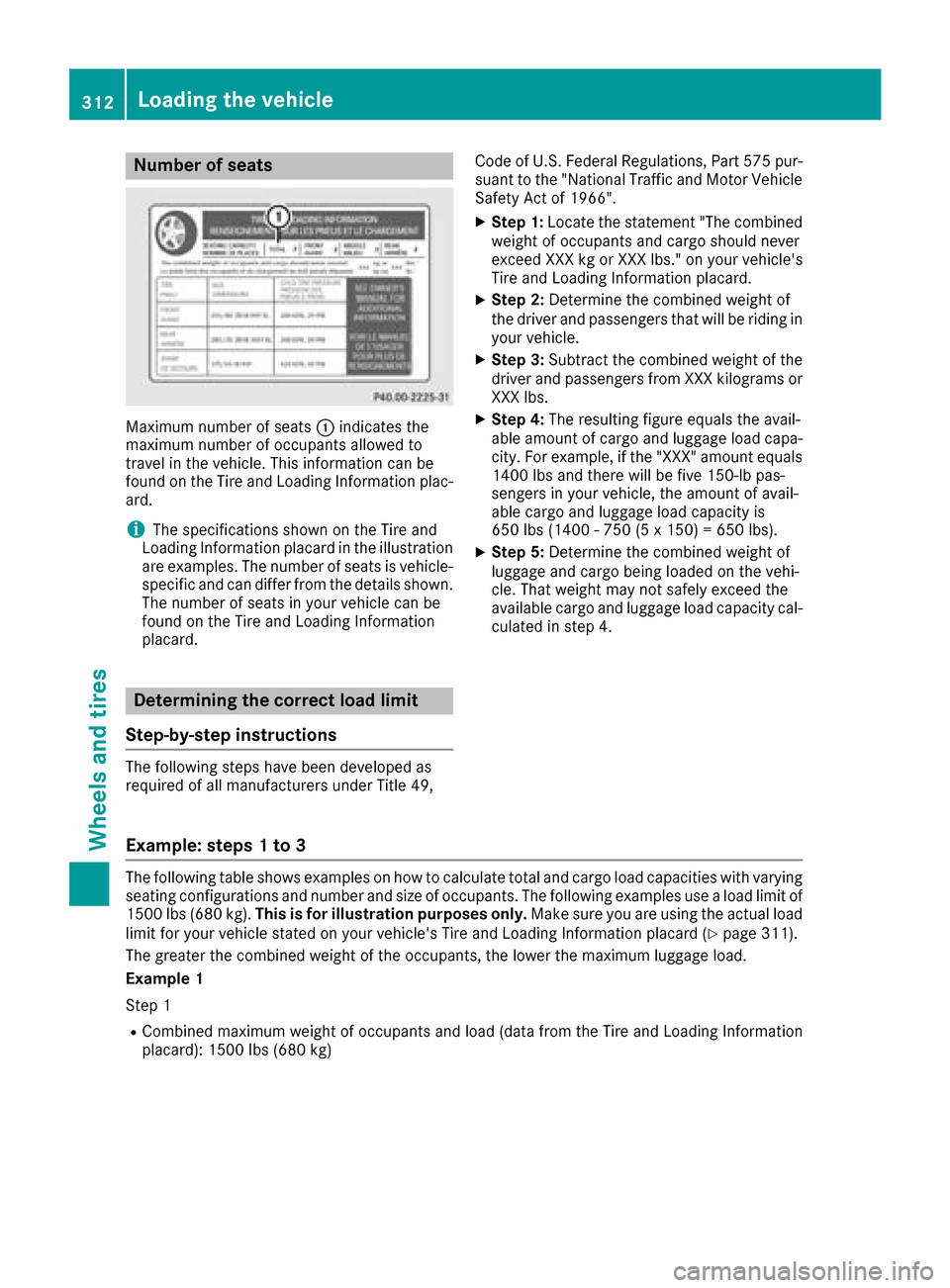
Maximum number of seats:indicates the
maximum number of occupants allowed to
travel in the vehicle. This information can be
found on the Tire and Loading Information plac-
ard.
iThe specifications shown on the Tire and
Loading Information placard in the illustration
are examples. The number of seats is vehicle-
specific and can differ from the details shown.
The number of seats in your vehicle can be
found on the Tire and Loading Information
placard.
Determining the correct load limit
Step-by-step instructions
The following steps have been developed as
required of all manufacturers under Title 49, Code of U.S. Federal Regulations, Part 575 pur-
suant to the "National Traffic and Motor Vehicle
Safety Act of 1966".
XStep 1: Locate the statement "The combined
weight of occupants and cargo should never
exceed XXX kg or XXX lbs." on your vehicle's
Tire and Loading Information placard.
XStep 2: Determine the combined weight of
the driver and passengers that will be riding in your vehicle.
XStep 3: Subtract the combined weight of the
driver and passengers from XXX kilograms or
XXX lbs.
XStep 4: The resulting figure equals the avail-
able amount of cargo and luggage load capa-
city. For example, if the "XXX" amount equals
1400 lbs and there will be five 150-lb pas-
sengers in your vehicle, the amount of avail-
able cargo and luggage load capacity is
650 lbs (1400 - 750 (5 x 150) = 650 lbs).
XStep 5: Determine the combined weight of
luggage and cargo being loaded on the vehi-
cle. That weight may not safely exceed the
available cargo and luggage load capacity cal- culated in step 4.
Example: steps 1 to 3
The following table shows examples on how to calculate total and cargo load capacities with varying
seating configurations and number and size of occupants. The following examples use a load limit of
1500 lbs (680 kg). This is for illustration purposes only. Make sure you are using the actual load
limit for your vehicle stated on your vehicle's Tire and Loading Information placard (
Ypage 311).
The greater the combined weight of the occupants, the lower the maximum luggage load.
Example 1
Step 1
RCombined maximum weight of occupants and load (data from the Tire and Loading Information
placard): 1500 lbs (680kg )
31 2Loading the vehicle
Wheels and tires
Page 317 of 338
!Avoid wheelspin. This can lead to damage to
the drive train.
The traction grades – from highest to lowest –
are AA, A, B and C. Those grades represent the
tire's ability to stop on wet pavement as meas-
ured under controlled conditions on specified
government test surfaces of asphalt and con-
crete. A tire marked C may have poor traction
performance.
The safe speed on a wet, snow covered or icy
road is always lower than on dry road surfaces.
You should pay special attention to road condi-
tions when temperatures are around freezing
point.
Mercedes-Benz recommends a minimum tread
depth of ãin (4 mm) on all four winter tires.
Observe the legally required minimum tire tread
depth (
Ypage 303). Winter tires can reduce the
braking distance on snow-covered surfaces in
comparison with summer tires. The braking dis-
tance is still much further than on surfaces that
are not icy or covered with snow. Take appro-
priate care when driving.
Further information on winter tires (M+S tires)
(
Ypage 304).
Temperature
GWARNING
The temperature grade for this tire is estab-
lished for a tire that is properly inflated and
not overloaded. Excessive speed, underinfla-
tion, or excessive loading, either separately or
in combination, can cause excessive heat
build-up and possible tire failure.
The temperature grades are A (the highest), B,
and C, representing the tire's resistance to the
generation of heat and its ability to dissipate
heat when tested under controlled conditions
on a specified indoor laboratory test wheel. Sus-
tained high temperature can cause the material
of the tire to degenerate and reduce tire life, and
excessive temperature can lead to sudden tire
failure. The grade C corresponds to a level of
performance which all passenger car tires must
meet under the Federal Motor Vehicle Safety
Standard No. 109. Grades B and A represent
higher levels of performance on the laboratory
test wheel than the minimum required by law.
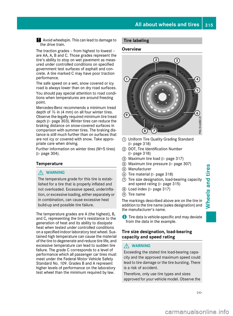
Tire labeling
Overview
:Uniform Tire Quality Grading Standard
(Ypage 318)
;DOT, Tire Identification Number
(Ypage 318)
=Maximum tire load (Ypage 317)
?Maximum tire pressure (Ypage 307)
AManufacturer
BTire material (Ypage 318)
CTire size designation, load-bearing capacity
and speed rating (Ypage 315)
DLoad index (Ypage 317)
ETire name
The markings described above are on the tire in
addition to the tire name (sales designation) and
the manufacturer's name.
iTire data is vehicle-specific and may deviate
from the data in the example.
Tire size designation, load-bearing
capacity and speed rating
GWARNING
Exceeding the stated tire load-bearing capa-
city and the approved maximum speed could
lead to tire damage or the tire bursting. There is a risk of accident.
Therefore, only use tire types and sizes
approved for your vehicle model. Observe the
All about wheels and tires315
Wheels and tires
Z
Page 318 of 338
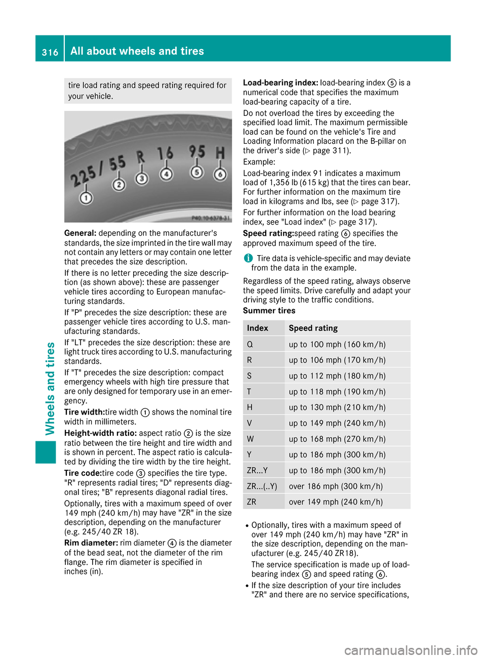
tire load rating and speed rating required for
your vehicle.
General:depending on the manufacturer's
standards, the size imprinted in the tire wall may
not contain any letters or may contain one letter
that precedes the size description.
If there is no letter preceding the size descrip-
tion (as shown above): these are passenger
vehicle tires according to European manufac-
turing standards.
If "P" precedes the size description: these are
passenger vehicle tires according to U.S. man-
ufacturing standards.
If "LT" precedes the size description: these are
light truck tires according to U.S. manufacturing
standards.
If "T" precedes the size description: compact
emergency wheels with high tire pressure that
are only designed for temporary use in an emer- gency.
Tire width: tire width:shows the nominal tire
width in millimeters.
Height-width ratio: aspect ratio;is the size
ratio between the tire height and tire width and
is shown in percent. The aspect ratio is calcula-
ted by dividing the tire width by the tire height.
Tire code:tire code =specifies the tire type.
"R" represents radial tires; "D" represents diag- onal tires; "B" represents diagonal radial tires.
Optionally, tires with a maximum speed of over
149 mph (240 km/h ) ma
y have "ZR" in the size
description, depending on the manufacturer
(e.g. 245/40 ZR 18).
Rim diameter: rim diameter?is the diameter
of the bead seat, not the diameter of the rim
flange. The rim diameter is specified in
inches (in). Load-bearing index:
load-bearing indexAis a
numerical code that specifies the maximum
load-bearing capacity of a tire.
Do not overload the tires by exceeding the
specified load limit. The maximum permissible
load can be found on the vehicle's Tire and
Loading Information placard on the B-pillar on
the driver's side (
Ypage 311).
Example:
Load-bearing index 91 indicates a maximum
load of 1,356 lb (615 kg) that the tires can bear.
For further information on the maximum tire
load in kilograms and lbs, see (
Ypage 317).
For further information on the load bearing
index, see "Load index" (
Ypage 317).
Speed rating: speed ratingBspecifies the
approved maximum speed of the tire.
iTire data is vehicle-specific and may deviate
from the data in the example.
Regardless of the speed rating, always observe
the speed limits. Drive carefully and adapt your
driving style to th
e traffic conditions.
Summer tires
IndexSpeed rating
Qup to 100 mph (160 km/h)
Rup to 106 mph (170 km/h)
Sup to 112 mph (180 km/h)
Tup to 118 mph (190 km/h)
Hup to 130 mph (210 km/h)
Vup to 149 mph (240 km/h)
Wup to 168 mph (270 km/h)
Yup to 186 mph (300 km/h)
ZR...Yup to 186 mph (300 km/h)
ZR...(..Y)over 186 mph (300 km/h)
ZRover 149 mph (240 km/h)
ROptionally, tires with a maximum speed of
over 149 mph (240 km/h) may have "ZR" in
the size description, depending on the man-
ufacturer (e.g. 245/40 ZR18).
The service specification is made up of load-
bearing index Aand speed rating B.
RIf the size description of your tire includes
"ZR" and there are no service specifications,
316All aboutwheels an d tires
Wheels and tires
Page 321 of 338
following specifications from the U.S. govern-
ment. The ratings are molded into the sidewall of
the tire.
Recommended tire pressures
The recommended tire pressure applies to the
tires mounted at the factory.
The Tire and Loading Information placard con-
tains the recommended tire pressures for cold
tires on a fully loaded vehicle and for the maxi-
mum permissible vehicle speed.
The tire pressure table contains the recommen-ded pressures for cold tires for various operat-
ing conditions, i.e. differing load and speed con-
ditions.
Increased vehicle weight due to optional
equipment
The combined weight of all standard and
optional equipment available for the vehicle,
regardless of whether it is actually installed on
the vehicle or not.
Rim
This is the part of the wheel on which the tire is
mounted.
GAWR (Gross Axle Weight Rating)
The GAWR is the maximum gross axle weight
rating. The actual load on an axle must never
exceed the gross axle weight rating. The gross
axle weight rating can be found on the vehicle
identification plate on the B-pillar on the driver's
side.
Speed rating
The speed rating is part of the tire identification. It specifies the speed range for which the tire is
approved.
GVW (Gross Vehicle Weight)
The gross vehicle weight includes the weight of
the vehicle including fuel, tools, the spare wheel,
accessories installed, occupants, luggage and
the drawbar noseweight, if applicable. The gross
vehicle weight must not exceed the gross vehi-
cle weight rating GVWR as specified on the vehi-
cle identification plate on the B-pillar on the
driver's side.
GVWR (Gross Vehicle Weight Rating)
The GVWR is the maximum permissible gross
weight of a fully loaded vehicle (the weight of the
vehicle including all accessories, occupants, fuel, luggage and the drawbar noseweight, if
applicable). The gross vehicle weight rating is
specified on the vehicle identification plate on
the B-pillar on the driver's side.
Maximum loaded vehicle weight
The maximum weight is the sum of:
Rthe curb weight of the vehicle
Rthe weight of the accessories
Rthe load limit
Rthe weight of the factory installed optional
equipment
Kilopascal (kPa)
Metric unit for tire pressure. 6.9 kPa corre-
sponds to 1 psi. Another unit for tire pressure is
bar. 100 kilopascals (kPa) are the equivalent of
1 bar.
Load index
In addition to the load-bearing index, the load
index may also be imprinted on the sidewall of
the tire. This specifies the load-bearing capacity
more precisely.
Curb weight
The weight of a vehicle with standard equipment
including the maximum capacity of fuel, oil and
coolant. It also includes the air-conditioning sys-
tem and optional equipment if these are instal-
led in the vehicle, but does not include passen-
gers or luggage.
Maximum load rating
The maximum tire load is the maximum permis-
sible weight in kilograms or lbs for which a tire is
approved.
Maximum permissible tire pressure
Maximum permissible tire pressure for one tire.
Maximum load on one tire
Maximum load on one tire. This is calculated by
dividing the maximum axle load of one axle by
two.
PSI (pounds per square inch)
A standard unit of measure for tire pressure.
Aspect ratio
Relationship between tire height and tire width
in percent.
All about wheels and tires319
Wheels and tires
Z
Page 324 of 338
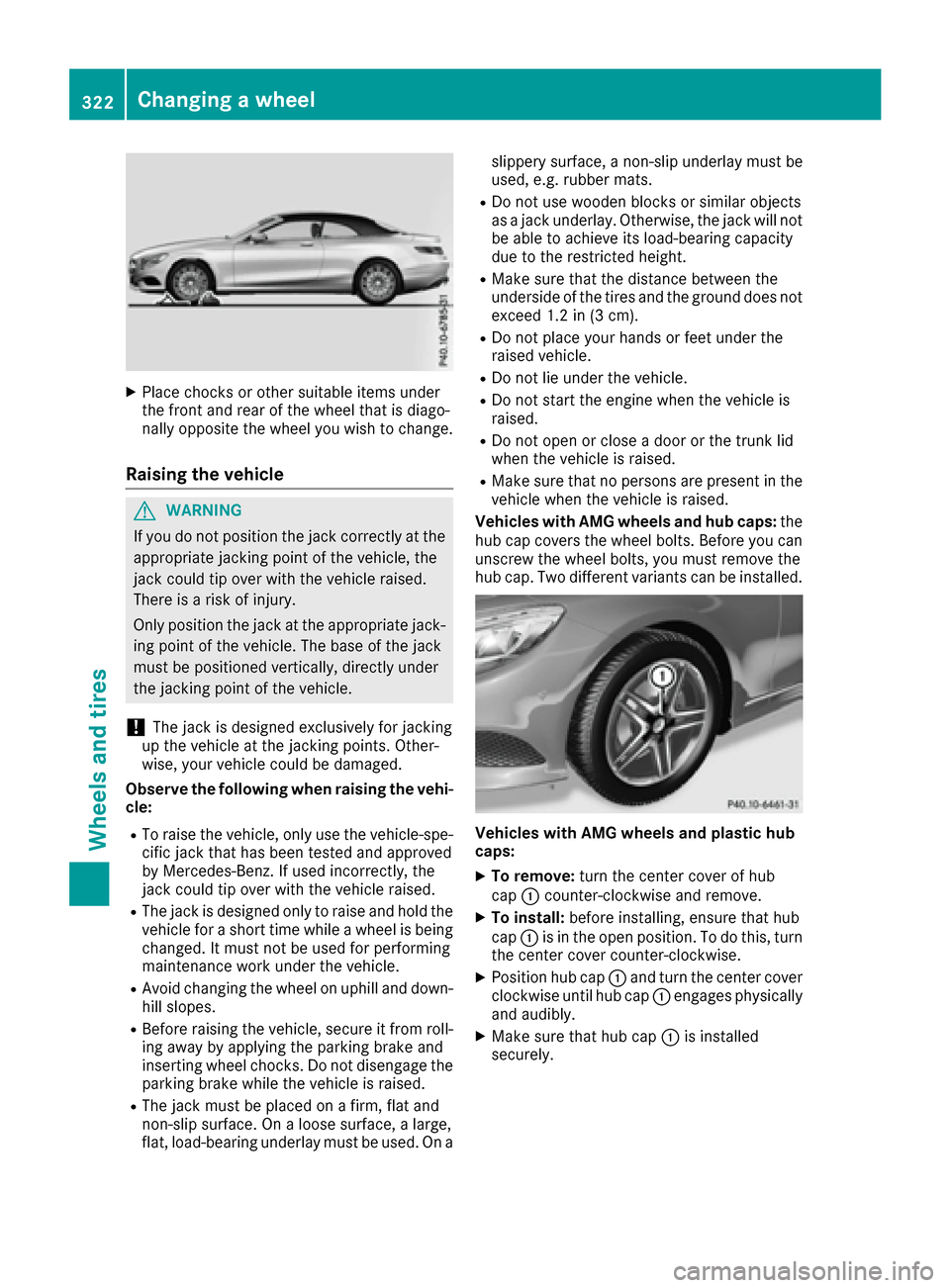
XPlace chocks or other suitable items under
the front and rear of the wheel that is diago-
nally opposite the wheel you wish to change.
Raising the vehicle
GWARNING
If you do not position the jack correctly at the
appropriate jacking point of the vehicle, the
jack could tip over with the vehicle raised.
There is a risk of injury.
Only position the jack at the appropriate jack-
ing point of the vehicle. The base of the jack
must be positioned vertically, directly under
the jacking point of the vehicle.
!The jack is designed exclusively for jacking
up the vehicle at the jacking points. Other-
wise, your vehicle could be damaged.
Observe the following when raising the vehi-
cle:
RTo raise the vehicle, only use the vehicle-spe-
cific jack that has been tested and approved
by Mercedes-Benz. If used incorrectly, the
jack could tip over with the vehicle raised.
RThe jack is designed only to raise and hold the
vehicle for a short time while a wheel is being
changed. It must not be used for performing
maintenance work under the vehicle.
RAvoid changing the wheel on uphill and down-
hill slopes.
RBefore raising the vehicle, secure it from roll-
ing away by applying the parking brake and
inserting wheel chocks. Do not disengage the
parking brake while the vehicle is raised.
RThe jack must be placed on a firm, flat and
non-slip surface. On a loose surface, a large,
flat, load-bearing underlay must be used. On a slippery surface, a non-slip underlay must be
used, e.g. rubber mats.
RDo not use wooden blocks or similar objects
as a jack underlay. Otherwise, the jack will not
be able to achieve its load-bearing capacity
due to the restricted height.
RMake sure that the distance between the
underside of the tires and the ground does not
exceed 1.2 in (3 cm).
RDo not place your hands or feet under the
raised vehicle.
RDo not lie under the vehicle.
RDo not start the engine when the vehicle is
raised.
RDo not open or close a door or the trunk lid
when the vehicle is raised.
RMake sure that no persons are present in the
vehicle when the vehicle is raised.
Vehicles with AMG wheels and hub caps: the
hub cap covers the wheel bolts. Before you can
unscrew the wheel bolts, you must remove the
hub cap. Two different variant
s can be installed.
Vehicles with AMG wheels and plastic hub
caps:
XTo remove: turn the center cover of hub
cap :counter-clockwise and remove.
XTo install: before installing, ensure that hub
cap :is in the open position. To do this, turn
the center cover counter-clockwise.
XPosition hub cap :and turn the center cover
clockwise until hub cap :engages physically
and audibly.
XMake sure that hub cap :is installed
securely.
322Changing a wheel
Wheels and tires