MERCEDES-BENZ S-CLASS CABRIOLET 2017 Owners Manual
Manufacturer: MERCEDES-BENZ, Model Year: 2017, Model line: S-CLASS CABRIOLET, Model: MERCEDES-BENZ S-CLASS CABRIOLET 2017Pages: 521, PDF Size: 10.48 MB
Page 401 of 521
#
Attach wheel spanner 3tosoc ket 2and
tighten theh ub cap clockwise.
Specified tightening torq ue: 25 Nm. #
Raise thev ehicle (→ page400). Ra
ising thev ehicle when changing awheel Re
quirements:
R Ther eareno persons in thev ehicle.
R The vehicle has been prepared foraw heel
ch ang e(→pag e396).
R The hub caps ha vebeen remo ved
( → pag e397).
Impor tant no tesonu singthej ack:
R onlyusethev ehicle-specific jac kthat has
been tested and appr ovedbyM ercedes-Benz
to raise thev ehicle.
R thej ackiso nlyd esigned forr aising and hold‐
ing thev ehicle foras horttime while awheel
is being changed and no tfor maintenance
wo rkunder thev ehicle. R
thej ackm ustbep laced on afirm, flat and
non-slip sur face. If necessar y,use alarge,
load-bearing, non-slip underla y.
R thef ootoft he jac kmustbep ositioned verti‐
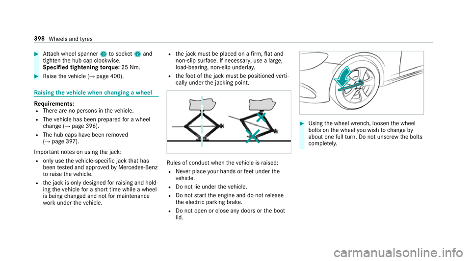
call yunder thej acking point. Ru
les of conduct when thev ehicle is raised:
R Neverp lace your hands or feet under the
ve hicle.
R Do no tlie under thev ehicle.
R Do no tstar tthe engine and do no trelease
th ee lectric parking brake.
R Do no topen or close an ydoor sort he boot
lid. #
Using thew heel wrench, loosen thew heel
bolts on thew heel youw ish tochang eby
about on efull turn. Do no tunscr ewtheb olts
comple tely. 398
Wheels and tyres
Page 402 of 521
Po
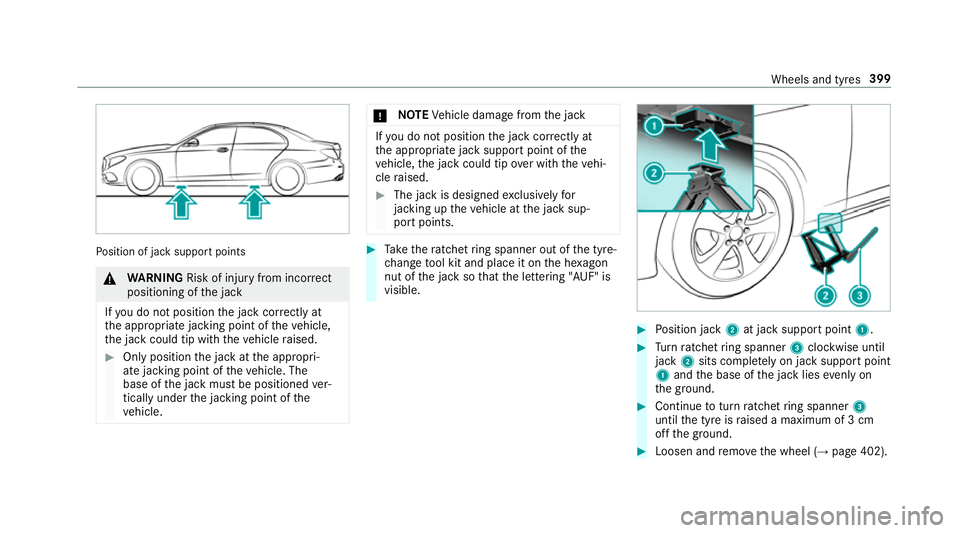
sition of jac ksuppor tpoints &
WARNING Risk of inju ryfrom incor rect
positioning of thej ack
If yo udon otpositio nthe jac kcorrectly at
th ea ppropriat ejacking point of thev ehicle,
th ej ackc ould tip wit hthe vehicle raised. #
Onlyposition thej ackatt he appropri‐
at ej acking point of thev ehicle. The
base of thej ackm ustbep ositioned ver‐
tically under thej acking point of the
ve hicle. *
NO
TEVehicle damag efromt he jack If
yo udon otpositio nthe jac kcorrectl yat
th ea ppropriat ejacks uppor tpoint of the
ve hicle, thej ackc ould tip overwitht he vehi‐
cle raised. #
The jac kisdesigned exclusively for
jacking up thev ehicle at thej acks up‐
por tpoints. #
Take ther atche tring sp anner ou tofthe tyre-
ch ang etool kit and place it on theh exagon
nut of thej acksot hatthel ette ring "AUF" is
visible. #
Position jack 2at jac ksuppor tpoint 1. #
Turn ratche tring sp anner 3clockwise until
jack 2sitsc omple tely on ja cksuppor tpoint
1 and theb ase of thej ackl ies evenlyon
th eg round. #
Continue totur nratche tring sp anner 3
unti lthe tyr eisraised amaximum of 3cm
of ft he ground. #
Loosen and remo vethew heel (→ page402). Wheels and tyres
399
Page 403 of 521
Re
moving awheel Re
quirement:
R The vehicle is raised (→ page398).
When changing awheel, avoid applying an yforce
to theb rake discs, since this could impair the
le ve lofc omfort when braking.
* NO
TEDama getothre adin gfromd irton
wheel bolts #
Do no tplace wheel bolt sinsandoron
ad irty sur face. #
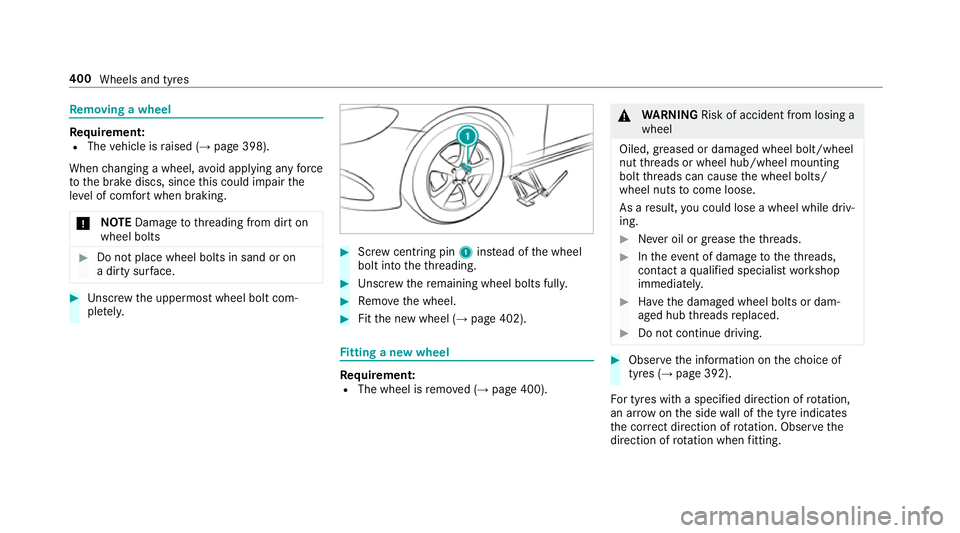
Unscr ew theu ppermos twheel bolt com‐
ple tely. #
Screw centring pin 1instead of thew heel
bolt int othe thre ading. #
Unscr ew ther emaining wheel bolt sfully. #
Remo vethew heel. #
Fitthen ew wheel (→ page402). Fi
ttin gan ewwheel Re
quirement:
R The wheel is remo ved( →pag e400). &
WARNING Risk of accident from losing a
wheel
Oiled, greased or damaged wheel bolt/wheel
nut thre ads or wheel hub/wheel mounting
bolt thre ads can caus ethe wheel bolts/
wheel nuts tocome loose.
As aresult, youc ould lose awheel while driv‐
ing. #
Nevero il or grease thet hreads. #
Inthee vent of dama getothet hreads,
contact aqualified specialis tworks hop
immediatel y. #
Have thed amaged wheel bolts or dam‐
aged hub thre ads replaced. #
Do no tcontinue driving. #
Obser vethei nformation on thec hoice of
tyres (→ page392).
Fo rtyres wit haspecified direction of rotation,
an ar rowonthes ide wall of thet yrei ndicates
th ec orrect di rection of rotation. Obse rvet he
direction of rotatio nw henf itting. 400
Wheels an dtyres
Page 404 of 521
#
Slide thew heel tobe mounted ont othe cen‐
tring pin and push it on. &
WARNING Risk of inju ryfrom tightening
whee lbolts and nuts
If yo ut ighten thew heel bolts or wheel nuts
when thev ehicle is raised, thej ackc ould tip. #
Onlytighten wheel bolts or wheel nuts
when thev ehicle is on theg round. #
Fors afet yr easons, onl yuse wheel bolts
whic hhaveb een appr ovedbyM ercedes-
Benz and fort he wheel in question. #
Tighten thew heel bolts until they aref inger-
tight. #
Unscr ew thec ent ring pin. #
Tighten thel astw heel bolt until it is finger-
tight. #
Ifth ec ollapsible emer gency spa rewheel has
been fitted ,infla tethec ollapsible emer gency
spa rewheel (→ page405). #
Lowe rthe vehicle (→ page403). Lo
weri ngthev ehicle af teraw heelchange Re
quirements:
R The ne wwheel has been fitted (→ page 400).
* NO
TEDama getothee mer gency spa re
wheel when lo wering thev ehicle If
th ec ollapsible emer gency spa rewheel is
no tinflated befor ethe vehicle is lo wered, its
ri mm aybe dama ged. #
Inflat ethe collapsibl eemer gency spa re
wheel befor elowe ring thev ehicle, using
th et yrei nflation compressor. #
Place ther atche tring sp anner ont othe he xa‐
gon nut of thej acksot hatthel ette ring "AB"
is visible. #
Tolowe rthe vehicle: turnthe ratche tring
sp an ner of thej acka nti-clockwise. #
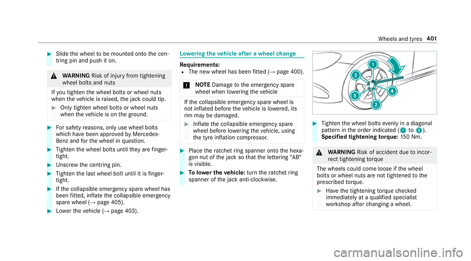
Tighten thew heel bolts evenlyinad iagonal
patter ninthe order indicated (1 to5 ).
Specified tightening torq ue: 150N m. &
WARNING Risk of accident du etoincor‐
re ct tigh tening torque
Th ew heel scould come loose if thew heel
bolts or wheel nuts ar enottightened tothe
prescribed torque. #
Have thet ightening torque checked
immediatel yataqualified specialist
wo rkshop af terc hanging awheel. Wheels and tyres
401
Page 405 of 521
#
Chec kthe tyr epressur eoft he newl ymoun‐
te dw heel and adjus taccording ly. #
Vehicles with tyr epressur elossw arning
sy stem: restar tt he tyr epressur eloss warn‐
ing sy stem (→ page392). #
Vehicles with atyrep ressur emonitoring
sy stem: restar tt he tyr epressur emonitoring
sy stem (→ page388).
Mak esuretoo bservethef ollowing fur ther rela‐
te ds ubjec t:
R Notesont yrep ressur e(→pag e385) Collapsible spar
ewheel Note
sont he collapsible spar ewheel &
WARNING Risk of accident caused by
incor rect wheel and tyr edimensions
The wheel or tyr esize and thet yret ype of
th ee mer gency spa rewheel or spar ewheel
and thew heel tobe replaced ma ydiffe r.
Mounting an emer gency spa rewheel/spare
wheel ma yseve rely impair thed riving char‐
acteristics. To
preve nt hazardous situations: #
Adapty our driving stylea ccording lyand
driv ecarefull y. #
Neverfit mo rethan on eemer gency
spa rewheel or spar ewheel that dif fers
in size. #
Onlyuse an emer gency spa rewheel or
spar ewheel of adiffe re nt size brie fly. #
Do no tswitcho ffESP ®
. #
>Ha vethee mer gency spa rewheel or
spar ewheel of adiffe re nt size replaced
at then eares tqualified specialis twork‐
shop. The ne wwheel mus thave the
cor rect dimensions. The collapsible spa
rewheel is an emer gency
whee lwhich is only suitable foru se foral imited
period of time and in arestricted manner in the
eve nt of aflat tyr e(e.g. until then eares twork‐
shop).
The tyr eside walls ar efolded when in transport
mode. Befor euse, thec ollapsible spar ewheel has
tobe inflated wit hthe accompanying com‐
pressor.
Chec kthe tyr epressur eoft he collapsibl espare
wheel oncef itted. Correct thep ressur easn ec‐
essar y.
The maximum permissible speed wit hacollapsi‐
ble spar ewheel fitted is 80 km/h.
Do no tfit sn ow ch ains wit hthe collapsibl espare
wheel.
Re place thec ollapsible spar ewheel af ters ix
ye arsatt he latest, rega rdless of wear.
% Ve
hicles with atyrep ressur elossw arn‐
ing sy stem: ifac ollapsible spar ewheel is
fi tted ,the tyr epressur eloss warning sy stem
cann otfunction reliabl y.Onl yrestart thes ys‐
te ma gain when thec ollapsible spar ewheel
has been replaced wit hanewwheel.
Ve hicles with atyrep ressur emonitoring
sy stem: ifac ollapsible spar ewheel is fitted
th et yrep ressur emonitoring sy stem cann ot
function reliably .Onlyr estart thes ystem
again when thec ollapsible spar ewheel has
been replaced wit hanewwheel. 402
Wheels and tyres
Page 406 of 521
Ve
hicles with atyrep ressur emonitoring
sy stem: foraf ewminutes af terac ollapsible
spar ewhee lisf itted, thes ystemm aystill
displa ythe tyr epressur eoft heremo ved
wheel.
Be sur etoalso obse rvet he following fur ther
re lated subjects:
R Notesont yrep ressur e(→pag e385)
R Tyre pressur etable (→ page386) Re
moving the collapsibl espar ew heel The collapsible spar
ewheel is secured in thec ol‐
lapsible spar ewheel bag in theb oot. #
Obser vethei nformation on mounting tyres
(→ pag e392). #
Open theb oot. #
Detach thef astening stra ps. #
Unhook ther etainin gspring hook softhefas‐
te ning stra ps from theb rack ets. #
Remo vethee mer gency spa rewheel bag
to ge ther wit hthe collapsibl espar ew heel. #
Open thee mer gency spa rewheel bag and
re mo vethec ollapsible spar ewheel. Inflating
thec ollapsible spa rewheel Re
quirements:
R Mount thec ollapsible spar ewheel as descri‐
bed. (→ page400)
R Remo vethet yrei nflation compressor from
th es towa ge well under theb ootfloor.
(→ pag e366)
* NO
TEDama getothec ollapsible spare
wheel when lo wering thev ehicle Lo
we ring thev ehicle without pr eviously
inflatin gthe collapsibl espar ew heel can
damag eits rim. #
Inflat ethe collapsibl espar ew heel using
th et yrei nflation compressor before
lo we ring thev ehicle. *
NO
TEOverheating du etothe tyr einfla‐
tion compressor running tool ong #
Do no trun thet yrei nflation compres‐
sor forl onger than tenm inutesw ithout
inter ruption. #
Pull connec tor4 and theh ose out of the
housing. #
Unscr ew thec ap from thev alveont he col‐
lapsible spar ewheel. Wheels and tyres
403
Page 407 of 521
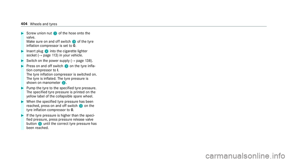
#
Screw unio nnut1 oftheh ose ont othe
va lve.
Mak esureona nd offswitch 3ofthet yre
inflation compressor is se tto0. #
Inser tplug 4intot he cigar ette lighter
soc ket(→pa ge113) in your vehicle. #
Switc hont he powersupp ly (→pag e138). #
Press on and of fswitch 3onthet yrei nfla‐
tion compressor toI.
The tyr einflation compressor is switched on.
The tyr eisinflated. The tyr epressur eis
shown on manome ter2. #
Pum pthe tyr etothe specified tyr epressure.
The specified tyr epressur eisp rinted on the
ye llo wl abel of thec ollapsible spar ewheel. #
When thes pecified tyr epressur ehas been
re ached, press on and of fswit ch 3 onthe
tyr einflatio ncompressor to0. #
Ifth et yrep ressur eish igher than thes peci‐
fi ed pressure, press pressur erelease valve
bu tton 5unti lthe cor rect tyr epressur ehas
bee nreached. 404
Wheels and tyres
Page 408 of 521
Note
sont echnical data
Mercedes-AMG vehicles: observet he no tesin
th eS upplement .Otherwise, youm ayfailto rec‐
ognise dangers.
The tech nica ldataw as de term ined in accord‐
anc ewithEUD irectives. The dat astatedo nly
applies tovehicles wit hstandar dequipment .You
can obtain fur ther information from aMercedes-
Benz Service Centre.
Onl yfor certain count ries: youc an find vehi‐
cle-specific vehicle dat ainthe COC documents
(CERTIFIC ATEOFC ONFORMITY) .These docu‐
ments ar edelivered wi thyour vehicle. On-boar
delectronics Note
sont ampering with thee ngine elec‐
tronics *
NO
TEPremature wearthro ugh improper
main tenance Improper maintenance ma
ycause vehicle
componentstow ear morequickl yand the ve
hicle's operating permit ma ybeinvalida‐
te d. #
Alw aysh ave workon thee ngine elec‐
tronics and related component scarried
out at aqualified specialis tworks hop. *
NO
TEIncreased wear and tear or dam‐
ag ec aused bymeasu resu nder take nto
inc rease per form ance Engin
emanagemen tmeasures unde rtaken to
inc rease per form anc ecan lead toinc reased
we ar and tear or damag etothe driv esystem. #
Do no tunder take engine management
measures toinc rease per form ance. Tw
o-w ayradios Note
sonf itting two- wayradios &
WARNING Risk of accident du eto
improper workon two-w ayradios
The elect romagnetic radiation from two-w ay
ra dios can inter fere wit hthe on-boar delec‐
tronics if RF transmit ters arem anipulated or
re trofitted inco rrectly.
This could jeopardise theo perating saf etyof
th ev ehicle. #
Yous hould ha veall workon electrical
and electronic component scarried out
at aq ualified specialis tworks hop. &
WARNING Risk of accident from incor‐
re ct ope ratio noft wo-way radios
If yo uo perat etwo -way radios inco rrectly in
th ev ehicle, thee lectromagnetic radiation
could inter fere wit hthe on-boar delectronics,
e.g.: Te
ch nica ldata 405
Page 409 of 521
R
ifth et wo -way radio is no tconnec tedto
an exterior aerial
R ifth ee xterio raerial is no tcorrectly
mounted or is no toflowreflection
This could jeopardise theo perating saf etyof
th ev ehicle. #
Have thel ow -reflectio nexterio raerial
fi tted at aqualified specialis tworks hop. #
When operating two-w ayradios in the
ve hicle, alw aysc onnect them tothe
lo w- reflection exterior aerial. *
NO
TEInva lidation of theo perating per‐
mit due tofailur etoc omply wi th the
instructions fori ns tallation and use The operatin
gpermit ma ybeinvalidated if
th ei nstruction sfor ins tallation and use of
two-w ayradios ar enotobser ved. #
Onlyuse appr oved frequency bands. #
Obser vethem aximum permissible out‐
put po werint hese frequency bands. #
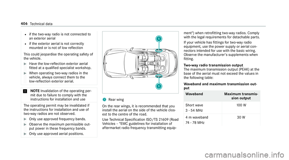
Onlyuse appr oved aerial positions. 1
Rear wing
On ther ear wings, it is recommended that you
ins tallth ea erial on thes ide of thev ehicle clos‐
es ttot he centre ofther oad.
Use Tech nica lSpecificatio nISO/T S21609 (Road
Ve hicles –"EMC guidelines fori ns tallation of
af te rm arke tradio frequency transmittin gequip‐ ment") when
retrofitting two-w ayradios. Comply
wit hthe legal requ irements ford etachable parts.
If yo ur vehicle has fitting sfor two-w ayradio
equipment ,use thep ower suppl yoraerial con‐
nector sintended foru se wit hthe basic wiring.
Obser vethem anufacturer's supplement swhen
fi tting.
Tw o-w ayradio transmission output
The maximum transmission outpu t(PEAK) at the
base of thea erial mus tnotexc eed thev alues in
th ef ollowing table:
Wa veband and maximum transmission out‐
put Wa
veband Maximum transmis‐
sion output
Shor twave
3-54M Hz 10
0W
4mw aveband
74 -78M Hz 30 W406
Tech nica ldata
Page 410 of 521
Wa
veband Maximum transmis‐
sion output
2mw aveband
14 4-1 74MHz 50 W
Tr unked radio sys‐
te m/T etra
380 -460 MHz 10 W
70 cm waveband
400 -460 MHz 35 W
Tw o-w ayradio
(2G/3G/4G) 10 WThe
following can be used in thev ehicle without
re strictions:
R RF transmitter switham aximum transmis‐
sion output of up to100mW
R RF transmitter switht ransmitter frequencies
in the3 80 -410 MHz waveband and amaxi‐
mum transmission output of up to2W
(trunked radio sy stem/T etra)
R Mobile phones (2G/3G/4G) Ther
eareno restrictions whe npositioning the
aerial on theo utside of thev ehicle fors ome
wav ebands.
This applies tothef ollowing wavebands:
R trunked radio sy stem/T etra
R 70 cm waveband
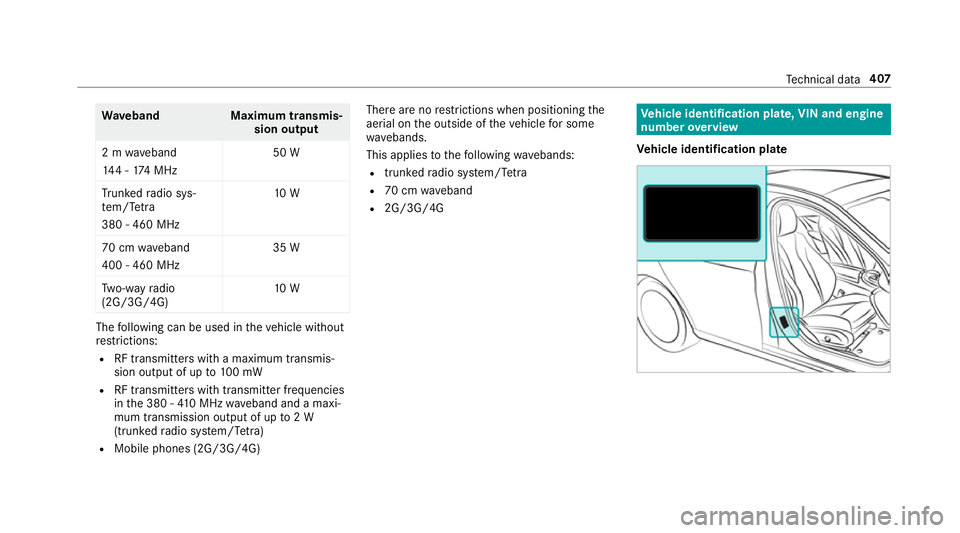
R 2G/3G/4G Ve
hicl eidentification plate, VIN and engine
number overview
Ve hicl eidentification plate Te
ch nica ldata 407