bonnet MERCEDES-BENZ S-CLASS COUPE 2015 Owners Manual
[x] Cancel search | Manufacturer: MERCEDES-BENZ, Model Year: 2015, Model line: S-CLASS COUPE, Model: MERCEDES-BENZ S-CLASS COUPE 2015Pages: 417, PDF Size: 13.42 MB
Page 9 of 417
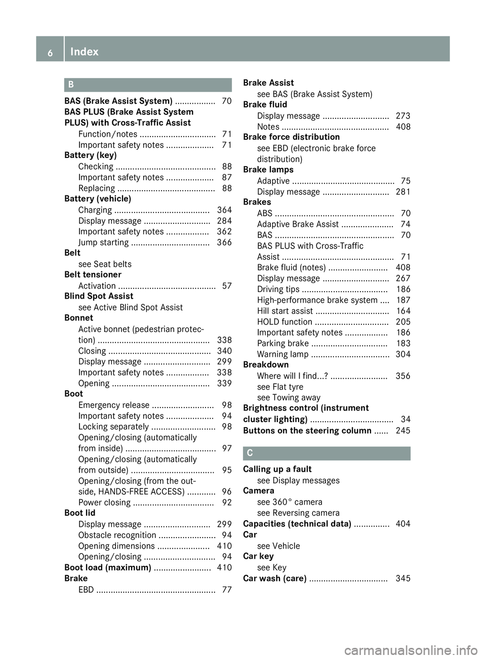
B
BAS (Brake Assist System) ................. 70
BAS PLUS (Brake Assist System
PLUS) with Cross-Traffic Assist
Function/note s................................ 71
Important safety notes .................... 71
Battery (key)
Checking .......................................... 88
Important safety notes .................... 87
Replacing ......................................... 88
Battery (vehicle)
Charging ........................................ 364
Display message ............................ 284
Important safety notes .................. 362
Jump starting ................................. 366
Belt
see Seat belts
Belt tensioner
Activation ......................................... 57
Blind Spot Assist
see Active Blind Spot Assist
Bonnet
Active bonnet (pedestrian protec-tion) ............................................... 338
Closing ........................................... 340
Display message ............................ 299
Important safety notes .................. 338
Opening ......................................... 339
Boot
Emergency release .......................... 98
Important safety notes .................... 94
Locking separately ........................... 98
Opening/closing (automatically
from inside) ...................................... 97
Opening/closing (automatically
from outside) ................................... 95
Opening/closing (from the out-
side, HANDS-FREE ACCESS) ............ 96
Power closing .................................. 92
Boot lid
Display message ............................ 299
Obstacle recognition ........................ 94
Opening dimensions ...................... 410
Opening/closing .............................. 94
Boot load (maximum) ........................ 410
Brake
EBD .................................................. 77 Brake Assist
see BAS (Brake Assist System)
Brake fluid
Display message ............................ 273
Notes ............................................. 408
Brake force distribution
see EBD (electronic brake force
distribution)
Brake lamps
Adaptive ........................................... 75
Display message ............................ 281
Brakes
ABS .................................................. 70
Adaptive Brake Assist ...................... 74
BAS .................................................. 70
BAS PLUS with Cross-Traffic
Assist ............................................... 71
Brake fluid (notes) ......................... 408
Display message ............................ 267
Driving tips .................................... 186
High-performance brake system .... 187
Hill start assist ............................... 164
HOLD function ............................... 205
Important safety notes .................. 186
Parking brake ................................ 183
Warning lamp ................................. 304
Breakdown
Where will I find...? ........................ 356
see Flat tyre
see Towing away
Brightness control (instrument
cluster lighting) ................................... 34
Buttons on the steering column ...... 245 C
Calling up a fault see Display messages
Camera
see 360° camera
see Reversing camera
Capacities (technical data) ............... 404
Car
see Vehicle
Car key
see Key
Car wash (care) ................................. 3456
Index
Page 19 of 417
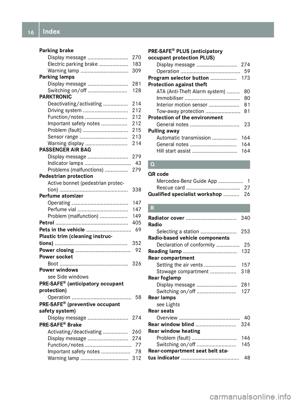
Parking brake
Display message ............................2 70
Electric parking brake .................... 183
Warning lamp ................................. 309
Parking lamps
Display message ............................ 281
Switching on/off ........................... 128
PARKTRONIC
Deactivating/activating ................. 214
Driving system ............................... 212
Function/notes ............................ .212
Important safety notes .................. 212
Problem (fault) ............................... 215
Sensor range ................................. 213
Warning displa y............................. 214
PASSENGER AIR BAG
Display message ............................ 279
Indicator lamps ................................ 43
Problems (malfunctions) ................ 279
Pedestrian protection
Active bonnet (pedestrian protec-tion) ............................................... 338
Perfume atomizer
Operating ....................................... 147
Perfume via l................................... 147
Problem (malfunction) ................... 149
Petrol .................................................. 405
Pets in the vehicle ............................... 69
Plastic trim (cleaning instruc-
tions) .................................................. 352
Power closing ...................................... 92
Power socket
Boot ............................................... 326
Power windows
see Side windows
PRE-SAFE ®
(anticipatory occupant
protection)
Operation ......................................... 58
PRE-SAFE ®
(preventive occupant
safety system)
Display message ............................ 274
PRE-SAFE ®
Brake
Activating/deactivating ................. 260
Display message ............................ 274
Function/note s................................ 77
Important safety notes .................... 78
Warning lamp ................................. 312 PRE-SAFE
®
PLUS (anticipatory
occupant protection PLUS)
Display message ............................ 274
Operation ......................................... 59
Program selector button .................. 173
Protection against theft
ATA (Anti-Theft Alarm system )......... 80
Immobiliser ...................................... 80
Interior motion sensor ..................... 81
Tow-away protection ........................ 81
Protection of the environment
General notes .................................. 23
Pulling away
Automatic transmission ................. 164
General notes ................................ 164
Hill start assist ............................... 164 Q
QR code Mercedes-Benz Guide App ................. 1
Rescue card ..................................... 27
Qualified specialist workshop ........... 26 R
Radiator cover ................................... 340
Radio
Selecting a station ......................... 253
Radio-based vehicle components
Declaration of conformity ................ 25
Reading lamp ..................................... 132
Rear compartment
Setting the air vents ...................... 157
Stowage compartment .................. 318
Rear foglamp
Display message ............................ 281
Switching on/of f........................... 127
Rear lamps
see Lights
Rear seats
Overview .......................................... 40
Rear window blind ............................ 324
Rear window heating
Problem (fault) ............................... 146
Switching on/of f........................... 145
Rear-compartment seat belt sta-
tus indicator ........................................ 4816
Index
Page 33 of 417
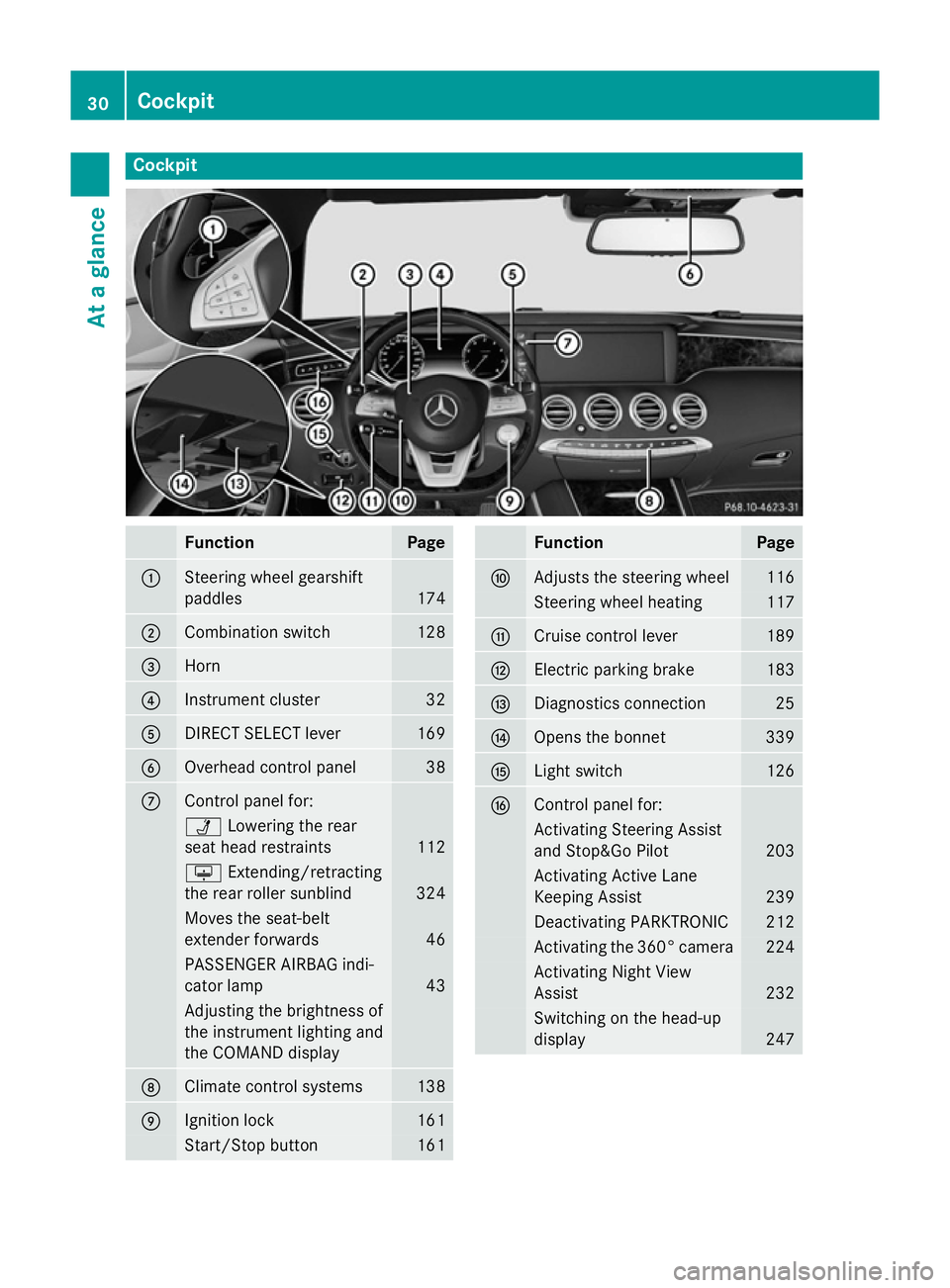
Cockpit
Function Page
:
Steering wheel gearshift
paddles
174
;
Combination switch 128
=
Horn
?
Instrument cluster 32
A
DIRECT SELECT lever 169
B
Overhead control panel 38
C
Control panel for:
Ü
Lowering the rear
seat head restraints 112
u
Extending/retracting
the rear roller sunblind 324
Moves the seat-belt
extender forwards 46
PASSENGER AIRBAG indi-
cator lamp
43
Adjusting the brightness of
the instrument lighting and
the COMAND display D
Climate control systems 138
E
Ignition lock 161
Start/Stop button 161 Function Page
F
Adjusts the steering wheel 116
Steering wheel heating 117
G
Cruise control lever 189
H
Electric parking brake 183
I
Diagnostics connection 25
J
Opens the bonnet 339
K
Light switch 126
L
Control panel for:
Activating Steering Assist
and Stop&Go Pilot
203
Activating Active Lane
Keeping Assist 239
Deactivating PARKTRONIC 212
Activating the 360° camera 224
Activating Night View
Assist 232
Switching on the head-up
display
24730
CockpitAt a glance
Page 34 of 417
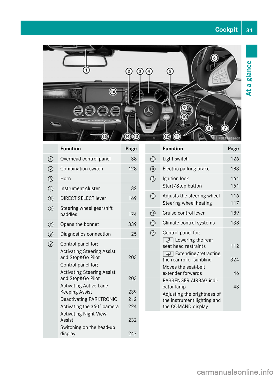
Function Page
:
Overhead control panel 38
;
Combination switch 128
=
Horn
?
Instrument cluster 32
A
DIRECT SELECT lever 169
B
Steering wheel gearshift
paddles
174
C
Opens the bonnet 339
D
Diagnostics connection 25
E
Control panel for:
Activating Steering Assist
and Stop&Go Pilot 203
Control panel for:
Activating Steering Assist
and Stop&Go Pilot
203
Activating Active Lane
Keeping Assist
239
Deactivating PARKTRONIC 212
Activating the 360° camera 224
Activating Night View
Assist
232
Switching on the head-up
display
247 Function Page
F
Light switch 126
G
Electric parking brake 183
H
Ignition lock 161
Start/Stop button 161
I
Adjusts the steering wheel 116
Steering wheel heating 117
J
Cruise control lever 189
K
Climate control systems 138
L
Control panel for:
Ü
Lowering the rear
seat head restraints 112
u
Extending/retracting
the rear roller sunblind 324
Moves the seat-belt
extender forwards
46
PASSENGER AIRBAG indi-
cator lamp
43
Adjusting the brightness of
the instrument lighting and
the COMAND display Cockpit
31At a glance
Page 83 of 417
The braking action of PRE-SAFE
®
Brake is
ended automatically if:
R you manoeuvre to avoid the obstacle
R there is no longer a risk of collision
R there is no longer an obstacle detected in
front of your vehicle STEER CONTROL
General notes STEER CONTROL helps you by transmitting a
noticeable steering force to the steering
wheel in the direction required for vehicle
stabilisation.
This steering support is provided in particular
if:
R both right wheels or both left wheels are on
a wet or slippery road surface when you
brake
R the vehicle starts to skid
Important safety notes i
Observe the "Important safety notes" sec-
tion (Y page 69).
No steering support is provided from STEER
CONTROL, if:
R ESP ®
is malfunctioning
R the steering is faulty
Power steering will, however, continue to
function. Protection against theft
Immobiliser
The immobiliser prevents your vehicle from
being started without the correct key.
X To activate with the key: remove the key
from the ignition lock.
X To activate with KEYLESS-GO: switch the
ignition off and open the driver's door.
X To deactivate: switch on the ignition. When leaving the vehicle, always take the key
with you and lock the vehicle. Anyone can
start the engine if a valid key has been left
inside the vehicle.
i The immobiliser is always deactivated
when you start the engine. ATA (Anti-Theft Alarm system)
X
To prime: lock the vehicle with the key or
KEYLESS-GO.
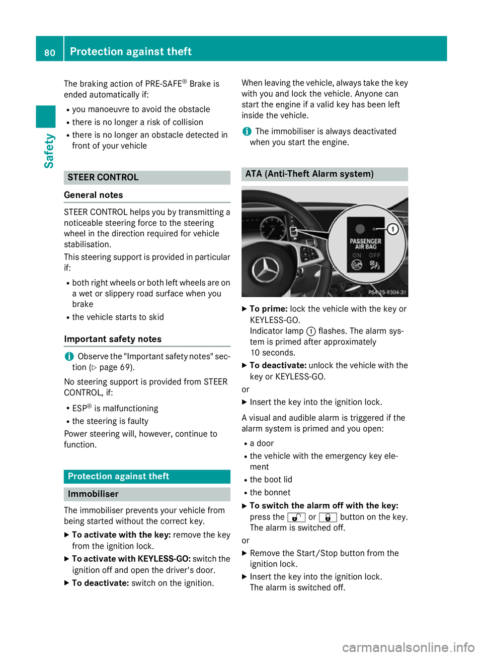
Indicator lamp :flashes. The alarm sys-
tem is primed after approximately
10 seconds.
X To deactivate: unlock the vehicle with the
key or KEYLESS-GO.
or X Insert the key into the ignition lock.
A visual and audible alarm is triggered if the
alarm system is primed and you open: R a door
R the vehicle with the emergency key ele-
ment
R the boot lid
R the bonnet
X To switch the alarm off with the key:
press the %or& button on the key.
The alarm is switched off.
or
X Remove the Start/Stop button from the
ignition lock.
X Insert the key into the ignition lock.
The alarm is switched off. 80
Protection against theftSafety
Page 137 of 417
!
Vehicles with a rain sensor: if the wind-
screen becomes dirty in dry weather con-
ditions, the windscreen wipers may be acti- vated inadvertently. This could damage the
windscreen wiper blades or scratch the
windscreen.
For this reason, you should always switch
off the windscreen wipers in dry weather. 1
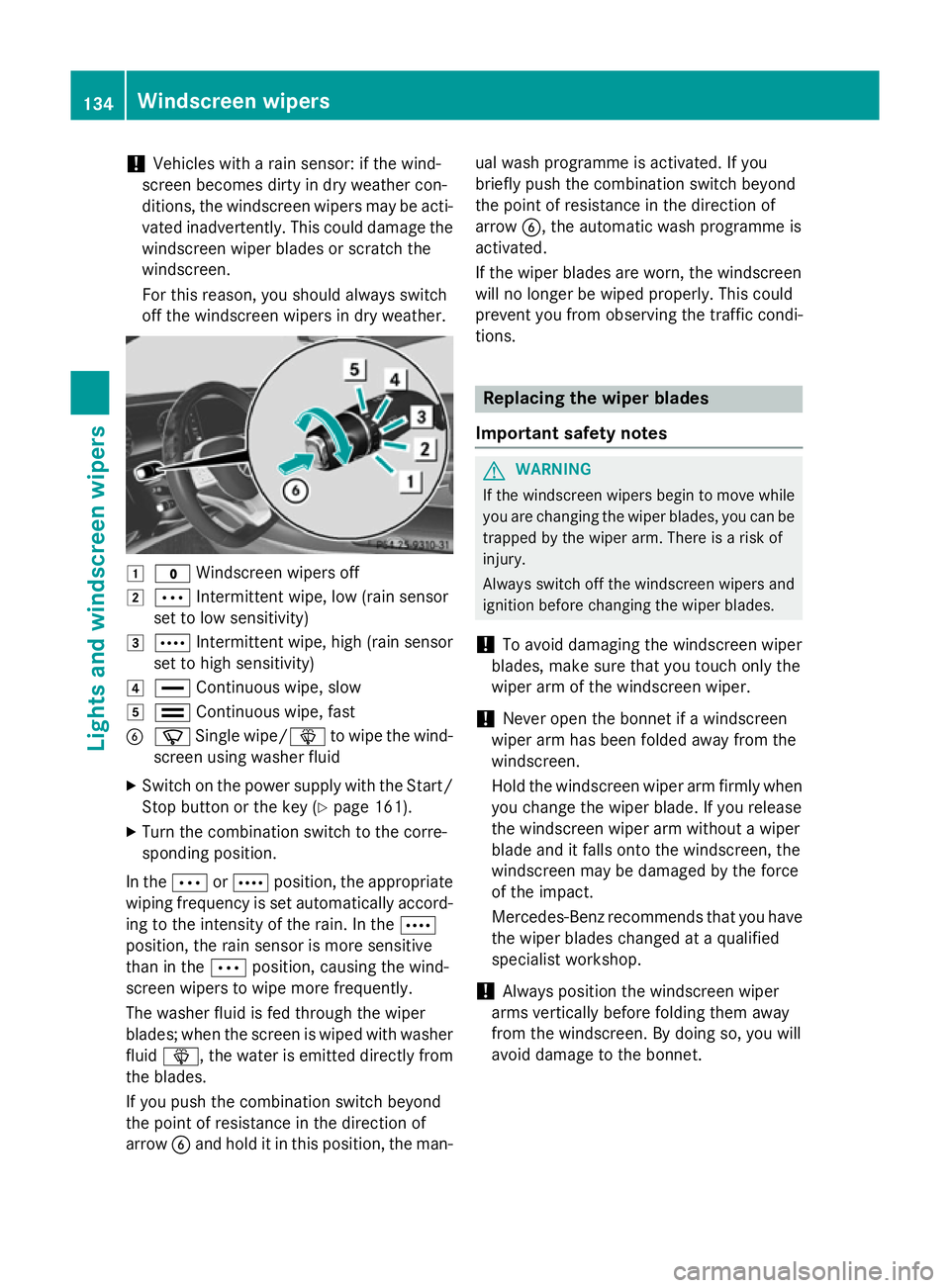
$ Windscreen wipers off
2 Ä Intermittent wipe, low (rain sensor
set to low sensitivity)
3 Å Intermittent wipe, high (rain sensor
set to high sensitivity)
4 ° Continuous wipe, slow
5 ¯ Continuous wipe, fast
B í Single wipe/î to wipe the wind-
screen using washer fluid
X Switch on the power supply with the Start/
Stop button or the key (Y page 161).
X Turn the combination switch to the corre-
sponding position.
In the ÄorÅ position, the appropriate
wiping frequency is set automatically accord- ing to the intensity of the rain. In the Å
position, the rain sensor is more sensitive
than in the Äposition, causing the wind-
screen wipers to wipe more frequently.
The washer fluid is fed through the wiper
blades; when the screen is wiped with washer
fluid î, the water is emitted directly from
the blades.
If you push the combination switch beyond
the point of resistance in the direction of
arrow Band hold it in this position, the man- ual wash programme is activated. If you
briefly push the combination switch beyond
the point of resistance in the direction of
arrow B, the automatic wash programme is
activated.
If the wiper blades are worn, the windscreen
will no longer be wiped properly. This could
prevent you from observing the traffic condi-
tions. Replacing the wiper blades
Important safety notes G
WARNING
If the windscreen wipers begin to move while
you are changing the wiper blades, you can be trapped by the wiper arm. There is a risk of
injury.
Always switch off the windscreen wipers and
ignition before changing the wiper blades.
! To avoid damaging the windscreen wiper
blades, make sure that you touch only the
wiper arm of the windscreen wiper.
! Never open the bonnet if a windscreen
wiper arm has been folded away from the
windscreen.
Hold the windscreen wiper arm firmly when you change the wiper blade. If you release
the windscreen wiper arm without a wiper
blade and it falls onto the windscreen, the
windscreen may be damaged by the force
of the impact.
Mercedes-Benz recommends that you have
the wiper blades changed at a qualified
specialist workshop.
! Always position the windscreen wiper
arms vertically before folding them away
from the windscreen. By doing so, you will
avoid damage to the bonnet. 134
Windscreen wipersLights and windscreen wipers
Page 138 of 417
Replacing the wiper blades
Moving the wiper blades to a vertical posi-
tion
On vehicles without KEYLESS-GO:
X Turn the key to position 0in the ignition
lock (Y page 161).
X Set the windscreen wipers to the °
position.
X Turn the key to position 1in the ignition
lock (Y page 161).
X As soon as the wiper arms are vertical to
the bonnet, turn the key to position 0in the
ignition lock (Y page 161).
X Remove the key.
X Fold the wiper arms away from the wind-
screen until you feel them snap into place.
On vehicles with KEYLESS-GO: X Switch off the engine.
X Remove your foot from the brake pedal.
X Set the windscreen wipers to position
°.
X Press the Start/Stop button repeatedly
until the windscreen wipers start.
X When the wiper arms have reached the ver-
tical position, press the Start/Stop button
repeatedly until the windscreen wipers
stop.
X Fold the wiper arms away from the wind-
screen until you feel them snap into place.
Removing the wiper blades X
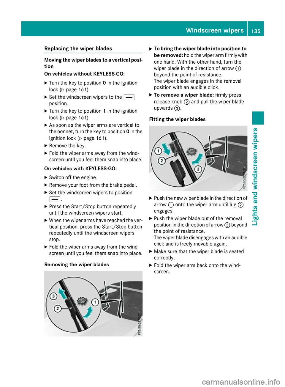
To bring the wiper blade into position to
be removed: hold the wiper arm firmly with
one hand. With the other hand, turn the
wiper blade in the direction of arrow :
beyond the point of resistance.
The wiper blade engages in the removal
position with an audible click.
X To remove a wiper blade: firmly press
release knob ;and pull the wiper blade
upwards =.
Fitting the wiper blades X
Push the new wiper blade in the direction of
arrow :onto the wiper arm until lug ;
engages.
X Push the wiper blade out of the removal
position in the direction of arrow =beyond
the point of resistance.
The wiper blade disengages with an audible
click and is freely movable again.
X Make sure that the wiper blade is seated
correctly.
X Fold the wiper arm back onto the wind-
screen. Windscreen wipers
135Lights and windscreen wipers Z
Page 158 of 417
Problems with the auxiliary heating/ventilation
Display messages
Possible causes/consequences and
M
MSolutions FAIL¨ The signal transmission between the transmitter and the vehicle is
faulty.
X Change your position in relation to the vehicle, moving closer if
necessary.
X Make another attempt to switch the auxiliary heating or auxiliary
ventilation on or off using the remote control. FAIL The auxiliary heating cannot be switched on or has switched itself
off.
The starter battery is not sufficiently charged.
X Charge the starter battery.
X Make another attempt to switch on the auxiliary heating or aux-
iliary ventilation using the remote control. The auxiliary heating cannot be switched on or has switched itself
off.
The fuel tank content is below the reserve fuel level.
X Refuel at the nearest filling station.
X Make another attempt to switch on the auxiliary heating using
the remote control. FAIL¯ The auxiliary heating or auxiliary ventilation cannot be switched on
or has switched itself off.
The auxiliary heating or auxiliary ventilation is faulty.
X Have the auxiliary heating or auxiliary ventilation checked at a
qualified specialist workshop. Adjusting the air vents
Important safety notes
G
WARNING
Very hot or very cold air can flow from the air vents. This could result in burns or frostbite in the immediate vicinity of the air vents. There
is a risk of injury.
Make sure that all vehicle occupants always
maintain a sufficient distance to the air out-
lets. If necessary, redirect the airflow to
another area of the vehicle interior. In order to ensure the direct flow of fresh air
through the air vents into the vehicle interior,
please observe the following notes:
R keep the air inlet between the windscreen
and the bonnet free of blockages, such as
ice, snow or leaves
R never cover the vents or ventilation grilles
in the vehicle interior Adjusting the air vents
155Climate control Z
Page 168 of 417
ECO start/stop function
Introduction The ECO start/stop function switches the
engine off automatically if the vehicle is stop-
ped under certain conditions.
When pulling away again, the engine starts
automatically. The ECO start/stop function
thereby helps you to reduce the fuel con-
sumption and emissions of your vehicle.
Important safety notes G
WARNING
If the engine is switched off automatically and you exit the vehicle, the engine is restarted
automatically. The vehicle may begin moving. There is a risk of accident and injury.
If you wish to exit the vehicle, always turn off
the ignition and secure the vehicle against
rolling away.
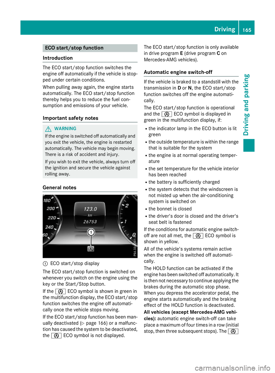
General notes :
ECO start/stop display
The ECO start/stop function is switched on
whenever you switch on the engine using the
key or the Start/Stop button.
If the è ECO symbol is shown in green in
the multifunction display, the ECO start/stop function switches the engine off automati-
cally once the vehicle stops moving.
If the ECO start/stop function has been man-
ually deactivated (Y page 166) or a malfunc-
tion has caused the system to be deactivated,
the è ECO symbol is not displayed. The ECO start/stop function is only available
in drive program E(drive program Con
Mercedes-AMG vehicles).
Automatic engine switch-off If the vehicle is braked to a standstill with the
transmission in Dor N, the ECO start/stop
function switches off the engine automati-
cally.
The ECO start/stop function is operational
and the èECO symbol is displayed in
green in the multifunction display, if:
R the indicator lamp in the ECO button is lit
green
R the outside temperature is within the range
that is suitable for the system
R the engine is at normal operating temper-
ature
R the set temperature for the vehicle interior
has been reached
R the battery is sufficiently charged
R the system detects that the windscreen is
not misted up when the air-conditioning
system is switched on
R the bonnet is closed
R the driver's door is closed and the driver's
seat belt is fastened
If the conditions for automatic engine switch- off are not all met, the èECO symbol is
shown in yellow.
All of the vehicle's systems remain active
when the engine is switched off automati-
cally.
The HOLD function can be activated if the
engine has been switched off automatically. It is then not necessary to continue applying the
brakes during the automatic stop phase.
When you depress the accelerator pedal, the engine starts automatically and the braking
effect of the HOLD function is deactivated.
All vehicles (except Mercedes-AMG vehi-
cles): automatic engine switch-off can take
place a maximum of four times in a row (initial
stop, then three subsequent stops). The è Driving
165Driving and parking Z
Page 248 of 417
The red band in the rev counter indicates the
engine's overrevving range.
The fuel supply is interrupted to protect the
engine when the red band is reached. Outside temperature display
You should pay special attention to road con-
ditions when temperatures are around freez-
ing point.
Bear in mind that the outside temperature
display indicates the measured air tempera-
ture and not the road surface temperature.
The outside temperature display is in the mul- tifunction display (Y page 246).
There is a short delay before a change in out- side temperature is shown in the multifunc-
tion display. Coolant temperature gauge
G
WARNING
If you open the bonnet while the engine is
overheating or while there is a fire in the
engine compartment, you could come into
contact with hot gases or other leaking ser-
vice products. There is a danger of injury.
Allow an overheating engine to cool down
before opening the bonnet. If there is a fire in the engine compartment, leave the bonnet
closed and notify the fire brigade.
The multifunction display shows the coolant
temperature gauge in the lower section of the rev counter (Y page 32).
At high outside temperatures and when driv-
ing uphill, the coolant temperature may rise.
Under normal operating conditions and with
the specified coolant level, the coolant tem-
perature may rise to 124 †. Operating the on-board computer
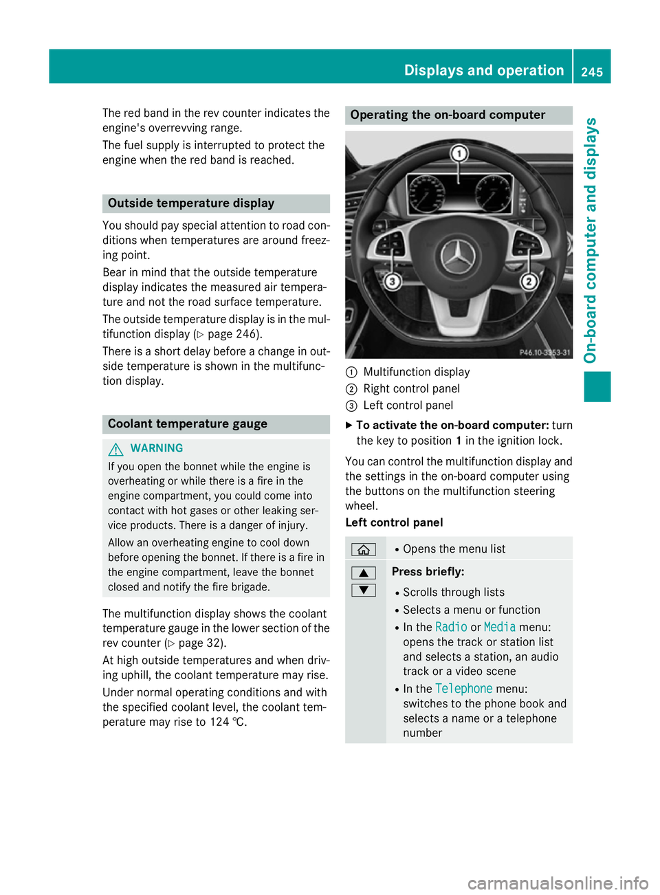
:
Multifunction display
; Right control panel
= Left control panel
X To activate the on-board computer: turn
the key to position 1in the ignition lock.
You can control the multifunction display and
the settings in the on-board computer using
the buttons on the multifunction steering
wheel.
Left control panel ò R
Opens the menu list 9
: Press briefly:
R Scrolls through lists
R Selects a menu or function
R In the Radio Radio orMedia
Media menu:
opens the track or station list
and selects a station, an audio
track or a video scene
R In the Telephone
Telephone menu:
switches to the phone book and
selects a name or a telephone
number Displays and operation
245On-board computer and displays Z