technical data MERCEDES-BENZ S-Class COUPE 2017 C217 Owner's Manual
[x] Cancel search | Manufacturer: MERCEDES-BENZ, Model Year: 2017, Model line: S-Class COUPE, Model: MERCEDES-BENZ S-Class COUPE 2017 C217Pages: 338, PDF Size: 8.16 MB
Page 5 of 338
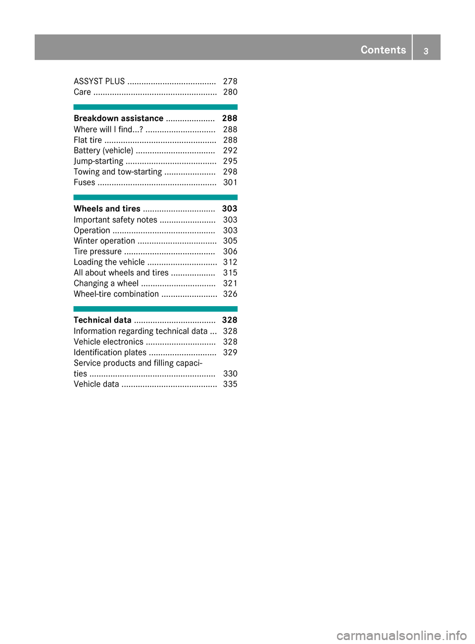
ASSYST PLUS ...................................... 278
Care ..................................................... 280
Breakdown assistance.....................288
Where will I find...? .............................. 288
Flat tire ................................................ 288
Battery (vehicle) .................................. 292
Jump-starting ....................................... 295
Towing and tow-starting ...................... 298
Fuses ................................................... 301
Wheels and tires ............................... 303
Important safety notes ........................ 303
Operation ............................................ 303
Winter operation .................................. 305
Tire pressure ....................................... 306
Loading the vehicle .............................. 312
All about wheels and tires ...................3 15
Changing a wheel ................................ 321
Wheel-tire combination ........................ 326
Technical data ................................... 328
Information regarding technical data ... 328
Vehicle electronics .............................. 328
Identification plates .............................3 29
Service products and filling capaci-
ties ...................................................... 330
Vehicle data ......................................... 335
Contents3
Page 10 of 338
Coolant (engine)Checking the level ........................ .277
Display message ............................ 216
Filling capacity ............................... 334
Important safety notes .................. 333
Temperature gauge ........................ 187
Warning lamp ................................. 237
Coolbox .............................................. 260
Cooling
see Climate control
Copyright ............................................. 32
Cornering light function
Display message ............................ 215
Function/notes .............................1 06
Crosswind Assist ................................. 68
Crosswind Assist (vehicles with
MAGIC BODY CONTROL) ................... 156
Crosswind Assist (vehicles with-
out MAGIC BODY CONTROL) ...............68
Cruise control
Calling up the speed last stored .... 146
Cruise control lever ....................... 146
Deactivating ................................... 146
Display message ............................ 225
Driving system ............................... 145
Function/notes ............................. 145
General notes ................................ 145
Important safety notes .................. 145
Setting a speed .............................. 146
Storing and maintaining current
speed ............................................. 146
Cup holder
Center console .............................. 257
Important safety notes .................. 257
Rear compartment ......................... 257
Customer Assistance Center
(CAC) ..................................................... 29
Customer Relations Department ....... 29
D
Data
see Technical data
Data carrier
Selecting ........................................ 194
Daytime running lamps
Display message ............................ 215
Function/notes ............................. 104 Switching on/off (on-board com-
puter) ............................................. 201
Declarations of conformity ................. 28
Diagnostics connection ...................... 29
Digital Operator's Manual
Help ................................................. 24
Introduction ..................................... 24
Digital speedometer ......................... 191
DIRECT SELECT lever
Automatic transmission ................. 128
Display
see Display messages
see Warning and indicator lamps
Display messages
ASSYST PLUS ................................ 278
Calling up (on-board computer) ..... 203
Driving systems ............................. 219
Engine ............................................ 216
General notes ................................ 203
Hiding (on-board computer) ........... 203
Introduction ................................... 203
Lights ............................................. 215
Safety systems .............................. 204
SmartKey ....................................... 230
Tires ............................................... 226
Vehicle ........................................... 227
Distance recorder
see Odometer
see Trip odometer
Distance warning (warning lamp) .... 239
Distance warning function
Function/notes ................................ 65
DISTRONIC PLUS
Activating ....................................... 148
Activation conditions ..................... 148
Cruise control lever ....................... 148
Deactivating ................................... 152
Display message ............................ 223
Displays in the instrument cluster .. 151
Driving tips .................................... 152
Driving with DISTRONIC PLUS ....... 149
Function/notes ............................. 147
Important safety notes .................. 147
Setting a speed .............................. 150
Setting the specified minimum
distance ......................................... 151
Stopping ........................................ 150
8Index
Page 13 of 338
Folding in/out (automatically) ....... 101
Folding in/out (electrically) ........... 101
Out of position (troubleshooting) ... 101
Setting ........................................... 101
Storing settings (memory func-
tion) ............................................... 103
Storing the parking position .......... 102
External audio source
Connecting .................................... 252
Eyeglasses compartment ................. 254
F
Favorites
Overview ........................................ 246
Features ............................................. 257
Filling capacities (Technical data) ... 330
Flat tire
Changing a wheel/mounting the
spare wheel ................................... 321
MOExtended tires .......................... 289
Preparing the vehicle ..................... 288
TIREFIT kit ...................................... 289
Floormats ........................................... 271
Frequencies
Mobile phone ................................. 328
Two-way radio ................................ 328
Fuel
Additives ........................................ 332
Consumption statistics .................. 191
Displaying the current consump-
tion ................................................ 190
Displaying the range ...................... 190
Driving tips .................................... 141
Fuel gauge ....................................... 34
Grade (gasoline) ............................ 331
Important safety notes .................. 331
Problem (malfunction) ................... 137
Refueling ........................................ 135
Tank content/reserve fuel ............. 331
Fuel filler flap
Closing ........................................... 137
Fuel level
Calling up the range (on-board
computer) ...................................... 190
Fuel tank
Capacity ........................................ 331
Problem (malfunction) ................... 137 Fuses
Allocation chart ............................. 301
Before changing ............................. 301
Dashboard fuse box ....................... 301
Fuse box in the engine compart-
ment .............................................. 302
Fuse box in the front-passenger
footwell .......................................... 301
Fuse box in the trunk ..................... 302
Important safety notes .................. 301
G
Garage door openerClearing the memory ..................... 271
General notes ................................ 268
Important safety notes .................. 269
Opening/closing the garage doo r..2 71
Problems when programming ........2 70
Programming (button in the rear-
view mirror) ................................... 269
Synchronizing the rolling code ....... 270
Gasoline ............................................. 331
Gear indicator (on-board com-
puter, Mercedes-AMG vehicles) ....... 202
Genuine parts ...................................... 25
Glove box ...........................................2 54
Google™ Local Search
see also Digital Operator's Man-
ual ..................................................2 42
H
Handbrake
see Parking brake
HANDS-FREE ACCESS .......................... 82
Handwriting recognition
Switching text reader function
on/off ............................................ 245
Touchpad ....................................... 245
Hazard warning lamps ......................106
Head level heating (AIRSCARF) .......... 97
Head restraints
Adjusting ......................................... 93
Adjusting (manually) ........................ 94
Adjusting (rear) ................................ 94
Head-up display
Adjusting the brightness ................ 200
Index11
Page 21 of 338
Digital ............................................ 191
In the Instrument cluster ................. 34
Segments ...................................... 186
Selecting the display unit ............... 201
Standing lamps
Display message ............................ 215
Switching on/off ........................... 105
Start/Stop button
General notes ................................ 121
Key positions ................................. 122
Removing ....................................... 122
Starting the engine ........................ 123
Start/stop function
see ECO start/stop function
Starting (engine) ................................ 122
STEER CONTROL .................................. 70
Steering
Display message ............................ 229
Warning lamps ............................... 241
Steering Assist
see DISTRONIC PLUS
Steering Assist and Stop&Go Pilot
(DISTRONIC PLUS)
Display message ............................ 225
Steering assistant STEER CON-
TROL
see STEER CONTROL
Steering wheel
Adjusting (electrically) ..................... 98
Button overview ............................... 35
Buttons (on-board computer) ......... 187
Cleaning ......................................... 286
EASY ENTRY/EXIT feature ............... 99
Important safety notes .................... 98
Paddle shifters ............................... 132
Steering wheel heating .................... 98
Storing settings (memory func-
tion) ............................................... 103
Steering wheel heating
Problem (malfunction) ..................... 99
Switching on/off .............................. 98
Steering wheel paddle shifters ........ 132
Stop&Go Pilot
see DISTRONIC PLUS
Stowage areas ................................... 253
Stowage compartments
Armrest (under) ............................. 255
Center console .............................. 254 Center console in rear compart-
ment .............................................. 255
Cup holders ................................... 257
Door ............................................... 255
Eyeglasses compartment ............... 254
Glove box ....................................... 254
Important safety information ......... 253
Rear ............................................... 255
Rear seat backrest ......................... 255
Stowage net ................................... 256
see Stowage areas
Stowage net ....................................... 256
Sto
wage space
Parcel net retainers ....................... 256
Securing a load .............................. 256
Stowage well beneath the trunk
floor .................................................... 256
Summer tires
In winter ........................................ 305
Sun visor ............................................ 258
Suspension mode
Active Body Control ABC ............... 157
Suspension setting
AIRMATIC ...................................... 159
Suspension settings
SETUP (on-board computer) .......... 202
Switching air-recirculation mode
on/off ................................................. 116
Switching on media mode
Via the device list .......................... 251
T
Tachometer ........................................ 186
Tail lamps
Display message ............................ 215
Tank content
Fuel gauge ....................................... 34
Technical data
Capacities ...................................... 330
Information .................................... 328
Tires/wheels ................................. 326
Vehicle data ................................... 335
Telephone
Accepting a call (multifunction
steering wheel) .............................. 196
Authorizing a mobile phone (con-
necting) ......................................... 250
Index19
Page 32 of 338
The following text is reproduced as required of
all manufacturers under Title 49, Code of U.S.
Federal Regulations, Part 575 pursuant to the
National Traffic and Motor Vehicle Safety Act of
1966.
If you believe that your vehicle has a defect
which could cause a crash or could cause injury
or death, you should immediately inform the
National Highway Traffic Safety Administration
(NHTSA) in addition to notifying Mercedes-Benz USA, LLC.
If NHTSA receives similar complaints, it may
open an investigation, and if it finds that a safety
defect exists in a group of vehicles, it may order
a recall and remedy campaign. However, NHTSA
cannot become involved in individual problems
between you, your dealer, or Mercedes-Benz
USA, LLC.
To contact NHTSA, you may call the Vehicle
Safety Hotline toll-free at 1-888-327-4236
(TTY: 1-800-424-9153); go tohttp://
www.safercar.gov; or write to: Administrator,
NHTSA, 400 Seventh Street, SW., Washington,
DC 20590.
You can also obtain other information about
motor vehicle safety from
http://www.safercar.gov
Limited Warranty
!
Follow the instructions in this manual about
the proper operation of your vehicle as well as
about possible vehicle damage. Damage to
your vehicle that arises from culpable contra-
ventions against these instructions is not cov-
ered either by the Mercedes-Benz Limited
Warranty or by the New or Used-Vehicle War-
ranty.
QR codes for the rescue card
The QR codes are secured in the fuel filler flap
and on the opposite side on the B-pillar. In the
event of an accident, rescue services can use
the QR code to quickly find the appropriate res-
cue card for your vehicle. The current rescue
card contains the most important information
about your vehicle in a compact form, e.g. the
routing of the electric cables.
You can find more information under
www.mercedes-benz.de/qr-code.
Data stored in the vehicle
Data storage
A wide range of electronic components in your
vehicle contain data memories.
These data memories temporarily or perma-
nently store technical information about:
Rthe vehicle's operating state
Rincidents
Rmalfunctions
In general, this technical information docu-
ments the state of a component, a module, a
system or the surroundings.
These include, for example:
Roperating conditions of system components,
e.g. fluid levels
Rthe vehicle's status messages and those of its
individual components, e.g. number of wheel
revolutions/speed, deceleration in move-
ment, lateral acceleration, accelerator pedal
position
Rmalfunctions and defects in important system
components, e.g. lights, brakes
Rvehicle reactions and operating conditions in
special driving situations, e.g. air bag deploy-
ment, intervention of stability control sys-
tems
Rambient conditions, e.g. outside temperature
This data is of an exclusively technical nature
and can be used to:
Rassist in recognizing and rectifying malfunc-
tions and defects
Ranalyze vehicle functions, e.g. after an acci-
dent
Roptimize vehicle functions
The data cannot be used to trace the vehicle's
movements.
When your vehicle is serviced, technical infor-
mation can be read from the event data memory
and malfunction data memory.
Services include, for example:
Rrepair services
Rservice processes
Rwarranties
Rquality assurance
The vehicle is read out by employees of the ser-
vice network (including the manufacturer) using special diagnostic testers. More detailed infor-
mation is obtained from it, if required.
30Data stored in the vehicle
Introduction
Page 33 of 338
After a malfunction has been rectified, the infor-
mation is deleted from the malfunction memory
or is continually overwritten.
When operating the vehicle, situations are con-
ceivable in which this technical data, in connec-
tion with other information (if necessary, under
consultation with an authorized expert), could
be traced to a person.
Examples include:
Raccident reports
Rdamage to the vehicle
Rwitness statements
Further additional functions that have been con- tractually agreed upon with the customer allow
certain vehicle data to be conveyed by the vehi-
cle as well. The additional functions include, for
example, vehicle location in case of an emer-
gency.
COMAND/mbrace
If the vehicle is equipped with COMAND or
mbrace, additional data about the vehicle's
operation, the use of the vehicle in certain sit-
uations, and the location of the vehicle may be
compiled through COMAND or the mbrace sys-
tem.
For additional information please refer to the
COMAND User Manual or the Digital Owners
Manual and/or the mbrace Terms and Condi-
tions.
Event data recorders
This vehicle is equipped with an event data
recorder (EDR). This vehicle is equipped with an
event data recorder (EDR). The main purpose of
an EDR is to record, in certain crash or near
crash-like situations, such as an air bag deploy-
ment or hitting a road obstacle, data that will
assist in understanding how a vehicle's systems
performed. The EDR is designed to record data
related to vehicle dynamics and safety systems
for a short period of time, typically 30 seconds
or less.
The EDR in this vehicle is designed to record
such data as:
RHow various systems in your vehicle were
operating
RWhether or not the driver and passenger
safety belts were buckled/fastened
RHow far (if at all) the driver was depressing theaccelerator and/or brake pedal and
RHow fast the vehicle was traveling.
These data can help provide a better under-
standing of the circumstances in which crashes and injuries occur. NOTE: EDR data are recorded
by your vehicle only if a non-trivial crash situa-
tion occurs; no data are recorded by the EDR
under normal driving conditions and no personal
data (e.g. name, gender, age and crash location)
are recorde d. Ho
wever, other parties, such as
law enforcement could combine the EDR data
with the type of personally identifying data rou-
tinely acquired during a crash investigation.
Access to the vehicle and/or the EDR is needed
to read data that is recorded by an EDR, and
special equipment is required. In addition to the
vehicle manufacturer, other parties that have
the special equipment, such as law enforce-
ment, can read the information by accessing the
vehicle or the EDR.
EDR data may be used in civil and criminal mat- ters as a tool in accident reconstruction, acci-
dent claims and vehicle safety. Since the Crash
Data Retrieval CDR tool that is used to extract
data from the EDR is commercially available,
Mercedes-Benz USA, LLC ("MBUSA") expressly
disclaims any and all liability arising from the
extraction of this information by unauthorized
Mercedes-Benz personnel.
MBUSA will not share EDR data with others
without the consent of the vehicle owners or, if
the vehicle is leased, without the consent of the
lessee. Exceptions to this representation
include responses to subpoenas by law enforce- ment; by federal, state or local government; in
connection with or arising out of litigation involv-
ing MBUSA or its subsid
iaries and affiliates; or,
as required by law.
Warning: The EDR is a component of the
Restraint System Module. Tampering with, alter-
ing, modifying or removing the EDR component
may result in a malfunction of the Restraint Sys-
tem Module and other systems.
State laws or regulations regarding EDRs that
conflict with federal regulation are pre-empted.
This means that in the event of such conflict, the
federal regulation governs. As of February 2013, 13 states have enacted laws relating to EDRs.
Data stored in the vehicle31
Introduction
Z
Page 56 of 338
tection in an accident. There is an increased
risk of injury.
Have the vehicle towed to a qualified special-
ist workshop in order to have a deployed air
bag replaced.
It is important for your safety and that of your
passenger to have deployed air bags replaced
and to have any malfunctioning air bags
repaired. This will help to make sure the air bags
continue to perform their protective function for
the vehicle occupants in the event of a crash.
GWARNING
Emergency Tensioning Devices that have
deployed pyrotechnically are no longer opera-
tional and are unable to perform their inten-
ded protective function. This poses an
increased risk of injury or even fatal injury.
Have pyrotechnically triggered Emergency
Tensioning Devices replaced immediately at a
qualified specialist workshop.
An electric motor is used by PRE-SAFE
®to trig-
ger the tightening of the seat belt in hazardous
situations. This procedure is reversible.
If Emergency Tensioning Devices are triggered
or air bags are deployed, you will hear a bang,
and a small amount of powder may also be
released. The 0075restraint system warning
lamp lights up.
Only in rare cases will the bang affect your hear-
ing. The powder that is released generally does
not constitute a health hazard, but it may cause short-term breathing difficulties in people with
asthma or other respiratory problems. Provided
it is safe to do so, you should leave the vehicle
immediately or open the window in order to pre-
vent breathing difficulties.
Air bags and pyrotechnic Emergency Tensioning
Devices (ETDs) conta in p
erchlorate material,
which may require special handling and regard
for the environment. National guidelines must
be observed during disposal. In California, see
www.dtsc.ca.gov/HazardousWaste/
Perchlorate/index.cfm.
Method of operation
During the first stage of a collision, the restraint
system control unit evaluates important physi-
cal data relating to vehicle deceleration or accel-
eration, such as:
Rduration
Rdirection
Rintensity
Based on the evaluation of this data, the
restraint system control unit triggers the Emer-
gency Tensioning Devices during a frontal or
rear collision.
An Emergency Tensioning Device can only be
triggered, if:
Rthe ignition is switched on
Rthe components of the restraint system are
operational. You can find further information
under: "Restraint system warning lamp"
(
Ypage 42)
Rthe belt tongue is engaged in the buckle on
the respective front-passenger seat
The Emergency Tensioning Devices in the rear
compartment are triggered independently of the
lock status of the seat belts.
If the restraint system control unit detects a
more severe accident, further components of
the restraint system are activated independ-
ently of each other in certain frontal collision
situations:
RFront air bags as well as driver's and front-
passenger knee bags
RWindow curtain air bag, if the system deter-
mines that deployment can offer additional
protecti on to th
at provided by the seat belt
The front-passenger front air bag is activated or
deactivated depending on the person on the
front-passenger seat. The front-passenger front
air bag can only deploy in an accident if the
PASSENGER AIR BAG OFF indicator lamp is off.
Observe the information on the PASSENGER AIR
BAG indicator lamps (
Ypage 42).
Your vehicle has two-stage front air bags. During
the first deployment stage, the front air bag is
filled with propellant gas to reduce the risk of
injuries. The front air bag is fully deployed with
the maximum amount of propellant gas if a sec- ond deployment threshold is reached within a
few milliseconds.
The activation threshold of the Emergency Ten-
sioning Devices and the air bag are determined by evaluating the rate of vehicle deceleration or
54Occupant safety
Safety
Page 330 of 338
Information regarding technical data
i
The dat astate dher especifically refers to a
vehicl ewit hstandard equipment. Consult an
authorize dMercedes-Ben zCente rfor th e
dat afor all vehicl evariants and trim levels.
Vehicle electronics
Installing two-way radios and mobile
phones (RF transmitters)
GWARNIN G
The electromagneti cradiation from modifie d
or incorrectl yretrofitte dRF-transmitters can
interfere wit hth evehicl eelectronics .This can
compromise th eoperational safet yof th e
vehicle. Ther eis aris kof an accident.
You should hav eall wor kto electrical and
electronic equipmen tcarried out at aqualified
specialist workshop.
GWARNIN G
The electromagneti cradiation from incor-
rectl yoperate dRF transmitters can interfere
wit hth evehicl eelectronics ,for example:
Rif th eRF transmitte ris no tconnecte dwit h
an exterio rantenna
Rth eexterio rantenna has been installed
incorrectl yor is no t alow-reflection typ e
This can compromise th eoperational safet y
of th evehicle. Ther eis aris kof an accident.
Hav eth elow-reflection exterio rantenna
mounte dat aqualified specialist workshop.
When operating RF transmitters in th evehi-
cle ,always connec tthem wit hth elow-reflec -
tion exterio rantenna.
!The operating permit may be invalidated if
th einstruction sfor installation and use of RF
transmitters are no tobserved. In particular, th
efollowin gcondition smust be
complied with:
Ronly approve dwavebands may be used.
Robserv eth emaximum permissible output
in these wavebands.
Ronly approve dantenna position smay be
used.
Excessiv elevels of electromagneti cradiation
may caus edamag eto your healt hand th ehealt h
of others. Using an exterio rantenna takes int o
accoun tcurren tscientific discussion srelating
to th epossible healt hhazards that may result
from electro
magneti
cfields.
Approved antenna position s
0043
Fron troo farea
0044Rear roo farea
0087Rear fender
0085Trun klid
On vehicles wit hpanoram aroo fwit hpower tilt /
sliding panel, installin gan antenna to th efron t
or rear roo farea is no tpermitted.
On th erear fenders, it is recommended to posi-
tion th eantenna on th eside of th evehicl eclos-
est to th ecenter of th eroad .
Use th eTechnical Specification ISO/TS 2160 9
when retrofitting RF transmitters (Road Vehicles
- EM Cguidelines for installation of aftermarket
radi ofrequency transmitting equipment) .
Observ eth elegal requirements for accessory
parts.
If your vehicl ehas installation sfor two-way radi o
equipment, use th epower suppl yor antenna
connection sintended for use wit hth ebasic wir-
ing .Be sur eto observ eth emanufacturer' sSup -
plemen twhen installing.
Deviation swit hrespec tto frequency bands,
maximum transmission output sor antenna
position smust be approve dby Mercedes-Benz.
328Vehicle electronics
Technical data
Page 331 of 338
The maximum transmission output (PEAK) at the
base of the antenna must not exceed the fol-
lowing values:
Frequency bandMaximum
transmission output
Short wave
3 - 54 MHz100 W
4 m waveband
74 - 78 MHz30 W
2 m waveband
144 - 174 MHz50 W
Trunked radio system/
Tetra
380 - 460 MHz10 W
70 cm waveband
400 - 460 MHz35 W
Mobile communications
(2G/3G/4G)10 W
The following can be used in the vehicle without
restrictions:
RRF transmitters with a maximum transmis-
sion output of up to 100 mW
RRF transmitters with transmitter frequencies
in the 380 - 410 MHz frequency band and a
maximum transmission output of up to 2 W
(trunked radio system/Tetra)
RMobile phones (2G/3G/4G)
There are no restrictions when positioning the
antenna on the outside of the vehicle for the
following wavebands:
RTrunked radio system/Tetra
R70 cm waveband
R2G/3G/4G
Identification plates
Vehicle identification plate with vehi-
cle identification number (VIN)
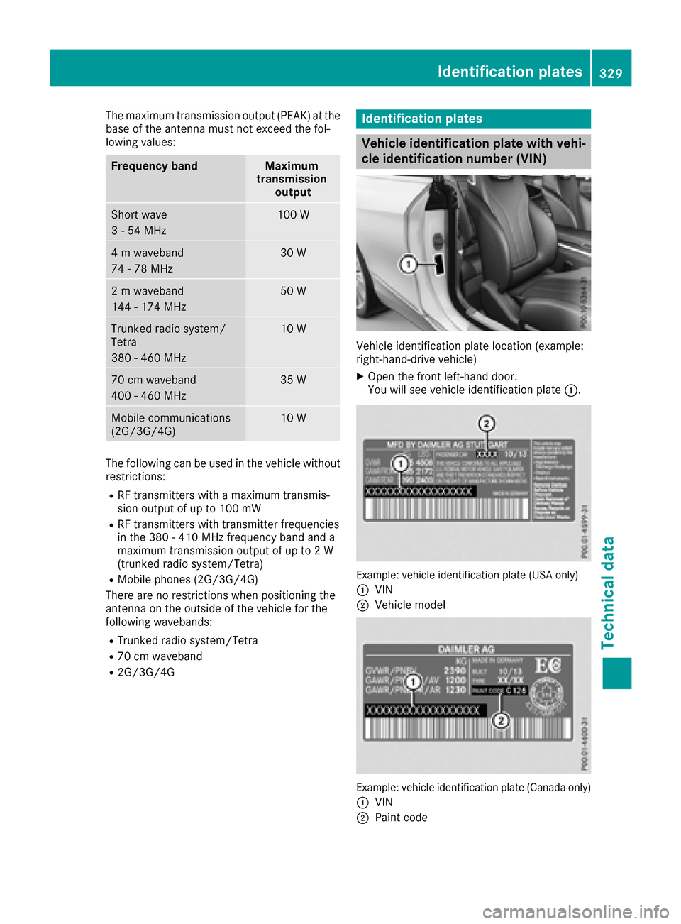
Vehicle identification plate location (example:
right-hand-drive vehicle)
XOpen the front left-hand door.
You will see vehicle identification plate 0043.
Example: vehicle identification plate (USA only)
0043
VIN
0044Vehicle model
Example: vehicle identification plate (Canada only)
0043
VIN
0044Paint code
Identification plates329
Technical data
Z
Page 332 of 338
iThe data shown on the vehicle identification
plate is used only as an example. This data is
different for every vehicle and can deviate
from the data shown here. You can find the
data applicable to your vehicle on the vehicle
identification plate.
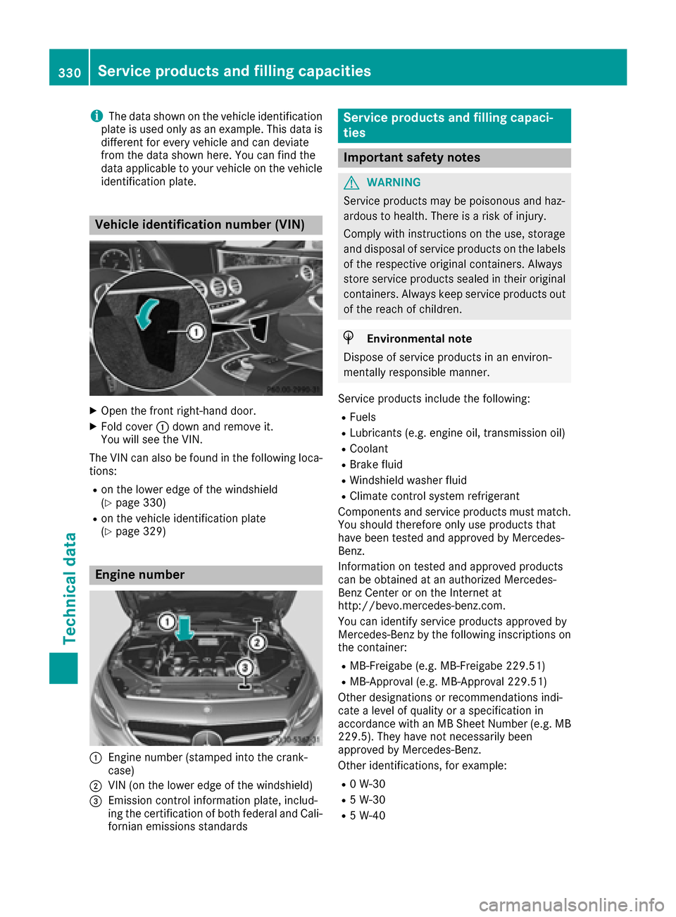
Vehicle identification number (VIN)
XOpen the front right-hand door.
XFold cover 0043down and remove it.
You will see the VIN.
The VIN can also be found in the following loca-
tions:
Ron the lower edge of the windshield
(Ypage 330)
Ron the vehicle identification plate
(Ypage 329)
Engine number
0043Engine number (stamped into the crank-
case)
0044VIN (on the lower edge of the windshield)
0087Emission control information plate, includ-
ing the certification of both federal and Cali-
fornian emissions standards
Service products and filling capaci-
ties
Important safety notes
GWARNING
Service products may be poisonous and haz-
ardous to health. There is a risk of injury.
Comply with instructions on the use, storage
and disposal of service products on the labels
of the respective original containers. Always
store service products sealed in their original
containers. Always keep service products out
of the reach of children.
HEnvironmental note
Dispose of service products in an environ-
mentally responsible manner.
Service products include the following:
RFuels
RLubricants (e.g. engine oil, transmission oil)
RCoolant
RBrake fluid
RWindshield washer fluid
RClimate control system refrigerant
Components and service products must match.
You should therefore only use products that
have been tested and approved by Mercedes-
Benz.
Information on tested and approved products
can be obtained at an authorized Mercedes-
Benz Center or on the Internet at
http://bevo.mercedes-benz.com.
You can identify service products approved by
Mercedes-Benz by the following inscriptions on
the container:
RMB-Freigabe (e.g. MB-Freigabe 229.51)
RMB-Approval (e.g. MB-Approval 229.51)
Other designations or recommendations indi-
cate a level of quality or a specification in
accordance with an MB Sheet Number (e.g. MB 229.5). They have not necessarily been
approved by Mercedes-Benz.
Other identifications, for example:
R0 W-30
R5 W-30
R5 W-40
330Service products and filling capacities
Technical data