steering MERCEDES-BENZ S-CLASS SEDAN 2013 Owners Manual
[x] Cancel search | Manufacturer: MERCEDES-BENZ, Model Year: 2013, Model line: S-CLASS SEDAN, Model: MERCEDES-BENZ S-CLASS SEDAN 2013Pages: 536, PDF Size: 24.14 MB
Page 461 of 536
Reduce Oil Level message appears, the
engine oil level is too high.
X
Have excess oil siphoned off.
! Do not add too much oil. Adding too much
oil can result in damage to the engine or the
catalytic converter. Have excess oil
siphoned off.
If the For Engine Oil Level Ignition
Must be On message appears:
X Turn the SmartKey to position 2 in the
ignition lock.
If the Need More Time to Check Engine
Oil Level message appears:
X If the engine is at normal operating
temperature: repeat the measurement
after about five minutes.
If the engine is not at normal operating
temperature (e.g. if the engine was only
started briefly): repeat the measurement
after about 30 minutes.
If the Engine Oil Level Not When
Engine On message appears:
X Switch off the engine.
X If the engine is at normal operating
temperature: wait about five minutes
before carrying out the measurement.
If the engine is not at normal operating
temperature, e.g. if the engine was only
started briefly: wait about 30 minutes
before carrying out the measurement.
i If you wish to cancel the measurement,
press
the % button on the multifunction
steering wheel.
Adding engine oil G
WARNING
If engine oil comes into contact with hot
engine
parts, it may ignite and you could burn
yourself. Do not spill any engine oil on hot
engine parts. H
Environmental note
When adding oil, take care not to spill any. If
oil enters the soil or waterways, it is harmful
to the environment.
! Use only engine oils and oil filters that
have been approved for vehicles equipped
with a service system. A list of the engine
oils and oil filters tested and approved in
accordance with the Mercedes-Benz
Specifications for Service Products can be
called up by visiting http://
www.mbusa.com (USA only). More
information about tested and approved
engine oils and oil filters is available from
any authorized Mercedes-Benz Center.
Damage
to the engine or exhaust system is
caused by the following:
R using engine oils and oil filters which
have not been specifically approved for
the service system.
R replacing the engine oil or oil filter after
the replacement interval required by the
service system has elapsed
R using engine oil additives.
! Do not add too much oil. If the oil level is
above the "max" mark on the dipstick, too
much oil has been added. This can lead to
damage to the engine or the catalytic
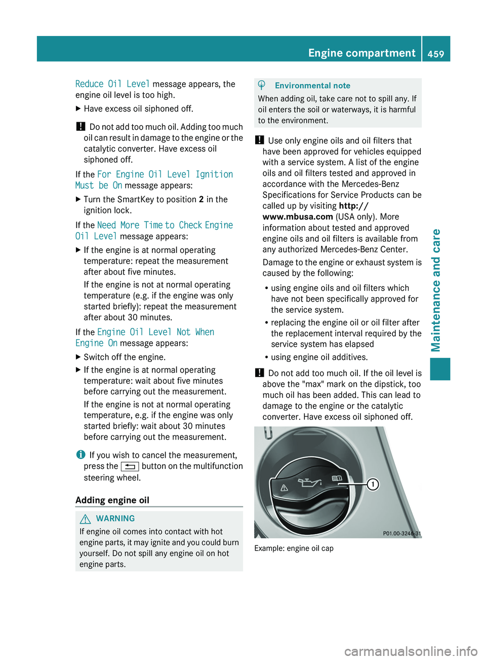
converter. Have excess oil siphoned off. Example: engine oil cap Engine compartment
459
Maintenance and care Z
Page 464 of 536
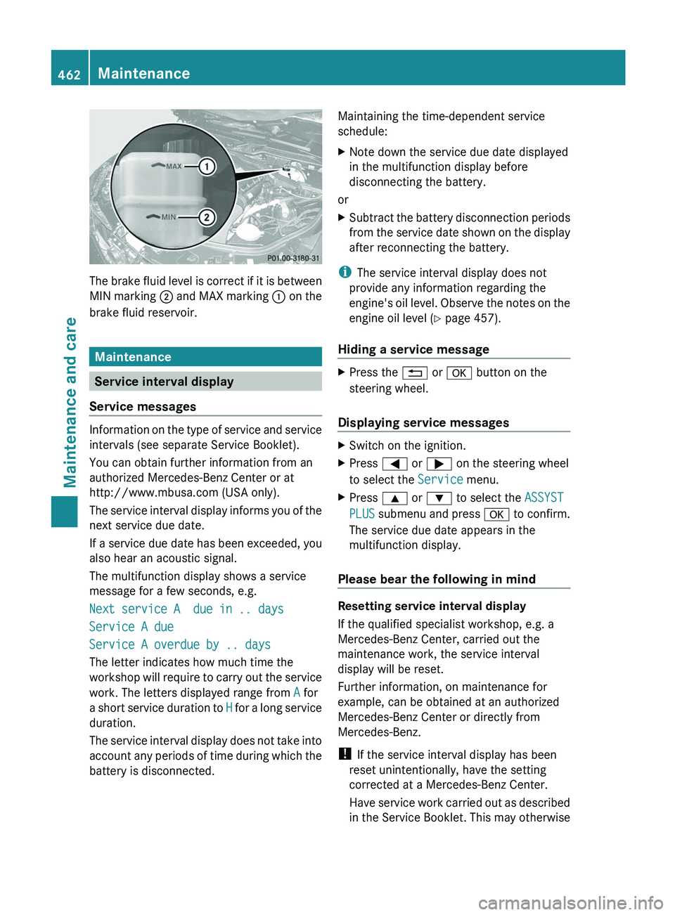
The brake fluid level is correct if it is between
MIN
marking ; and MAX marking : on the
brake fluid reservoir. Maintenance
Service interval display
Service messages Information on the type of service and service
intervals (see separate Service Booklet).
You can obtain further information from an
authorized Mercedes-Benz Center or at
http://www.mbusa.com (USA only).
The
service interval display informs you of the
next service due date.
If a service due date has been exceeded, you
also hear an acoustic signal.
The multifunction display shows a service
message for a few seconds, e.g.
Next service A due in .. days
Service A due
Service A overdue by .. days
The letter indicates how much time the
workshop will require to carry out the service
work. The letters displayed range from A for
a short service duration to H for a long service
duration.
The service interval display does not take into
account any periods of time during which the
battery is disconnected. Maintaining the time-dependent service
schedule:
X
Note down the service due date displayed
in the multifunction display before
disconnecting the battery.
or
X Subtract the battery disconnection periods
from
the service date shown on the display
after reconnecting the battery.
i The service interval display does not
provide any information regarding the
engine's
oil level. Observe the notes on the
engine oil level ( Y page 457).
Hiding a service message X
Press the % or a button on the
steering wheel.
Displaying service messages X
Switch on the ignition.
X Press = or ; on the steering wheel
to select the Service menu.
X Press 9 or : to select the ASSYST
PLUS
submenu and press a to confirm.
The service due date appears in the
multifunction display.
Please bear the following in mind Resetting service interval display
If the qualified specialist workshop, e.g. a
Mercedes-Benz Center, carried out the
maintenance work, the service interval
display will be reset.
Further information, on maintenance for
example, can be obtained at an authorized
Mercedes-Benz Center or directly from
Mercedes-Benz.
!
If the service interval display has been
reset unintentionally, have the setting
corrected at a Mercedes-Benz Center.
Have
service work carried out as described
in the Service Booklet. This may otherwise 462
Maintenance
Maintenance and care
Page 470 of 536
G
WARNING
Please do not forget that your primary
responsibility is to drive the vehicle. A driver's
attention to the road must always be his/her
primary focus when driving. For your safety
and the safety of others, stop before trying to
remove window fogging or cleaning the
window in front of the Night View Assist Plus
camera.
Bear in mind that at a speed of just 30 mph
(approximately 50 km/h), your vehicle is
covering a distance of 44 feet (approximately
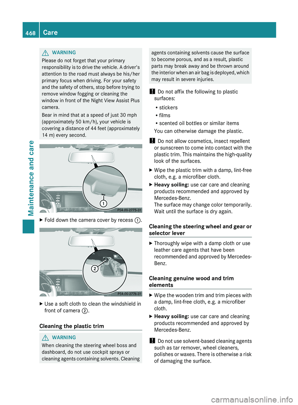
14 m) every second. X
Fold down the camera cover by recess :.X
Use a soft cloth to clean the windshield in
front of camera ;.
Cleaning the plastic trim G
WARNING
When cleaning the steering wheel boss and
dashboard, do not use cockpit sprays or
cleaning
agents containing solvents. Cleaning agents containing solvents cause the surface
to become porous, and as a result, plastic
parts may break away and be thrown around
the
interior when an air bag is deployed, which
may result in severe injuries.
! Do not affix the following to plastic
surfaces:
R stickers
R films
R scented oil bottles or similar items
You can otherwise damage the plastic.
! Do not allow cosmetics, insect repellent
or sunscreen to come into contact with the
plastic trim. This maintains the high-quality
look of the surfaces.
X Wipe the plastic trim with a damp, lint-free
cloth, e.g. a microfiber cloth.
X Heavy soiling: use car care and cleaning
products recommended and approved by
Mercedes-Benz.
The
surface may change color temporarily.
Wait until the surface is dry again.
Cleaning the steering wheel and gear or
selector lever X
Thoroughly wipe with a damp cloth or use
leather care agents that have been
recommended
and approved by Mercedes-
Benz.
Cleaning genuine wood and trim
elements X
Wipe the wooden trim and trim pieces with
a damp, lint-free cloth, e.g. a microfiber
cloth.
X Heavy soiling: use car care and cleaning
products recommended and approved by
Mercedes-Benz.
! Do
not use solvent-based cleaning agents
such as tar remover, wheel cleaners,
polishes or waxes. There is otherwise a risk
of damaging the surface. 468
Care
Maintenance and care
Page 485 of 536
Towing and tow-starting
Important safety notes
G
WARNING
Hybrid vehicles: be sure to read the "HYBRID"
supplement. Otherwise, you could fail to
recognize dangers. G
WARNING
If you tow the vehicle, you must use a rigid
towing bar if:
R the engine is not running.
R there is a brake system malfunction.
R there is a malfunction in the power supply
or the vehicle's electrical system.
The
power assistance for the steering and the
brake force booster do not work when the
engine is not running. You will need more
force to steer and brake, you may have to
depress the brake pedal with maximum force.
Before towing away, make sure that the
steering can be moved and is not locked.
If you tow or tow-start another vehicle, its
weight must not exceed the maximum
permissible gross vehicle weight of your
vehicle. G
WARNING
The vehicle is braked when the HOLD function
or DISTRONIC PLUS is activated. Therefore,
deactivate
HOLD and DISTRONIC PLUS if the
vehicle is to be towed.
It is better to have the vehicle transported
than to have it towed.
! You may only tow the vehicle a maximum
distance of 30 miles (50 km). A towing
speed of 30 mph (50 km/h) must not be
exceeded.
For towing distances over 30 miles
(50 km), the vehicle must loaded onto a
transporter.
! Make sure that the electric parking brake
is released. If the electric parking brake is
faulty, visit a qualified specialist workshop. !
Only
secure the tow rope or tow bar at the
towing eyes. Otherwise, the vehicle could
be damaged.
! Do not use the towing eye for recovery,
as this could damage the vehicle. If in
doubt, recover the vehicle with a crane.
! When towing, pull away slowly and
smoothly. If the tractive power is too high,
the vehicles could be damaged.
! Do not tow with sling-type equipment.
This could damage the vehicle.
! When towing vehicles with KEYLESS-GO,
use the key instead of the Start/Stop
button. Otherwise, the automatic
transmission may shift to position P when
the driver's or front-passenger door are
opened, which could lead to damage to the
transmission.
The automatic transmission must be in
position N when the vehicle is being towed.
The battery must be connected and charged.
Otherwise, you:
R cannot turn the SmartKey to position 2 in
the ignition lock
R cannot shift the automatic transmission to
position N
i Before the vehicle is towed, switch off the
automatic locking feature ( Y page 264).
You could otherwise be locked out when
pushing or towing the vehicle. Installing/removing the towing eye
Installing the towing eye X
Remove the towing eye from the vehicle
tool kit ( Y page 472). G
WARNING
The exhaust tail pipe may be hot. You could
burn yourself if you touch the tail pipe. Be
particularly careful when removing the rear
cover. Towing and tow-starting
483
Breakdown assistance Z
Page 486 of 536
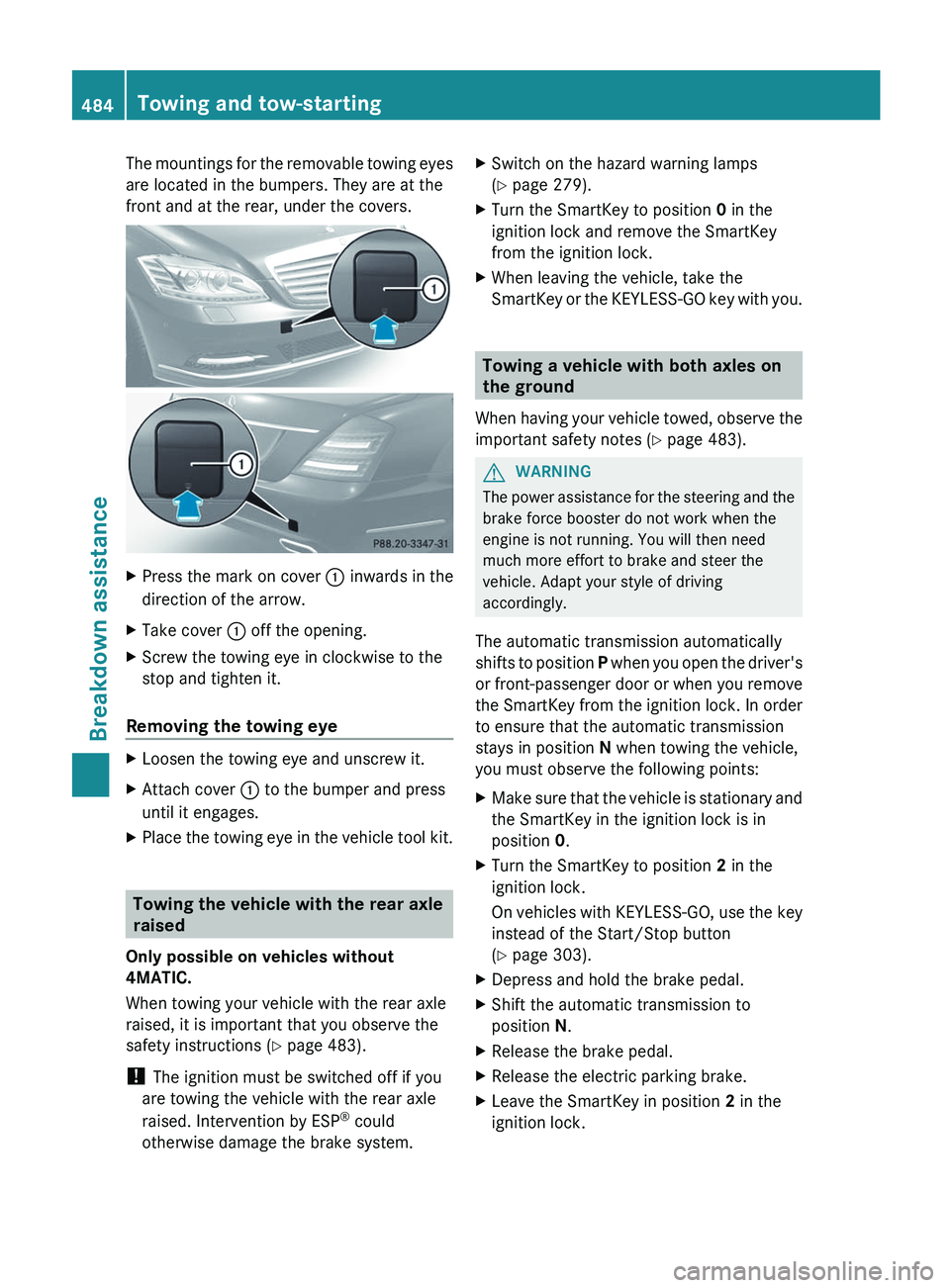
The mountings for the removable towing eyes
are located in the bumpers. They are at the
front and at the rear, under the covers.
X
Press the mark on cover : inwards in the
direction of the arrow.
X Take cover : off the opening.
X Screw the towing eye in clockwise to the
stop and tighten it.
Removing the towing eye X
Loosen the towing eye and unscrew it.
X Attach cover : to the bumper and press
until it engages.
X Place the towing eye in the vehicle tool kit. Towing the vehicle with the rear axle
raised
Only possible on vehicles without
4MATIC.
When towing your vehicle with the rear axle
raised, it is important that you observe the
safety instructions ( Y page 483).
! The ignition must be switched off if you
are towing the vehicle with the rear axle
raised. Intervention by ESP ®
could
otherwise damage the brake system. X
Switch on the hazard warning lamps
(Y page 279).
X Turn the SmartKey to position 0 in the
ignition lock and remove the SmartKey
from the ignition lock.
X When leaving the vehicle, take the
SmartKey
or the KEYLESS-GO key with you. Towing a vehicle with both axles on
the ground
When
having your vehicle towed, observe the
important safety notes ( Y page 483). G
WARNING
The power assistance for the steering and the
brake force booster do not work when the
engine is not running. You will then need
much more effort to brake and steer the
vehicle. Adapt your style of driving
accordingly.
The automatic transmission automatically
shifts
to position P when you open the driver's
or front-passenger door or when you remove
the SmartKey from the ignition lock. In order
to ensure that the automatic transmission
stays in position N when towing the vehicle,
you must observe the following points:
X Make sure that the vehicle is stationary and
the SmartKey in the ignition lock is in
position 0.
X Turn the SmartKey to position 2 in the
ignition lock.
On
vehicles with KEYLESS-GO, use the key
instead of the Start/Stop button
(Y page 303).
X Depress and hold the brake pedal.
X Shift the automatic transmission to
position N.
X Release the brake pedal.
X Release the electric parking brake.
X Leave the SmartKey in position 2 in the
ignition lock.484
Towing and tow-starting
Breakdown assistance
Page 487 of 536
Transporting the vehicle
The towing eye can be used to pull the vehicle
onto a trailer or transporter for transporting
purposes.
X Turn the SmartKey to position 2 in the
ignition lock.
X Shift the automatic transmission to
position N.
As soon as the vehicle is loaded:
X Prevent the vehicle from rolling away by
applying the electric parking brake.
X Shift the automatic transmission to
position P.
X Turn the SmartKey to position 0 in the
ignition lock and remove the SmartKey
from the ignition lock.
X Secure the vehicle.
! Only
lash the vehicle down by the wheels
or wheel rims, not by parts of the vehicle
such as axle or steering components.
Otherwise, the vehicle could be damaged. Notes for 4MATIC vehicles
! Vehicles
with 4MATIC must not be towed
with either the front or the rear axle raised,
as doing so will damage the transmission.
If the vehicle has transmission damage or
damage to the front or rear axle, have it
transported on a transporter or trailer.
In the event of damage to the electrical
system
If the battery is defective, the automatic
transmission will be locked in position P. To
shift the automatic transmission to position
N, you must provide power to the vehicle's
electrical system in the same way as when
jump-starting (Y page 481).
Have the vehicle transported on a transporter
or trailer. Tow-starting (emergency starting)
! Vehicles with automatic transmission
must not be started by tow-starting. This
could otherwise damage the transmission. Fuses
Important safety notes
The
fuses in your vehicle serve to close down
faulty circuits. If a fuse blows, all the
components on the circuit and their functions
stop operating. G
WARNING
Only use fuses approved by Mercedes-Benz
with
the specified amperage for the system in
question and do not attempt to repair or
bridge a blown fuse. Using other than
approved fuses or using repaired or bridged
fuses may cause an overload leading to a fire,
and/or cause damage to electrical
components and/or systems. Have the cause
determined and remedied by an authorized
Mercedes-Benz Center.
Blown fuses must be replaced with fuses of
the same rating, which you can recognize by
the color and value. The fuse ratings are listed
in the fuse allocation chart. An authorized
Mercedes-Benz Center will be happy to
advise you.
i If a fuse has blown, contact a breakdown
service or an authorized Mercedes-Benz
Center.
If the newly inserted fuse also blows, have the
cause traced and rectified at a qualified
specialist workshop, e.g. an authorized
Mercedes-Benz Center.
! Only use fuses that have been approved
for Mercedes-Benz vehicles and which
have the correct fuse rating for the system
concerned. Otherwise, components or
systems could be damaged. Fuses
485
Breakdown assistance Z
Page 495 of 536
impairs cornering ability and reduces driving
stability.
Adapt your driving style accordingly.
Have the spare wheel replaced by a normal
wheel with an M+S tire at the nearest
Mercedes-Benz Center. Snow chains
For safety reasons, Mercedes-Benz
recommends that you only use snow chains
which have been specially approved for your
vehicle by Mercedes-Benz, or are of a
corresponding standard of quality.
! You must drive at raised vehicle level if
snow chains have been mounted. The
vehicle could otherwise be damaged.
! There is not enough space for snow
chains on some wheel sizes. Observe the
information
under "Tires and wheels" in the
"Technical Data" section to avoid damage
to the vehicle or the wheels.
R Only use snow chains when driving on
roads completely covered by snow. Do not
exceed the maximum permissible speed of
30 mph (50 km/h). Remove the snow
chains as soon as possible when you are no
longer driving on snow-covered roads.
R Local regulations may restrict the use of
snow chains. Applicable regulations must
be observed if you wish to mount snow
chains.
R Snow chains must not be mounted on
emergency spare wheels.
If you intend to mount snow chains, please
bear the following points in mind:
R you may not attach snow chains to all
wheel-tire combinations; see the
information under "Wheel and tire
combinations" in the "Wheels and tires"
section.
R mount snow chains only in pairs and only
to the rear wheels. Observe the
manufacturer's installation instructions. !
If snow chains are mounted on the front
wheels, the snow chains could grind
against
the bodywork or components of the
chassis. This could result in damage to the
vehicle or the tires.
! Vehicles with steel wheels: if you wish
to mount snow chains on steel wheels,
make sure that you remove the respective
wheels' hubcaps first. The hubcaps may
otherwise be damaged.
i You may wish to deactivate
ESP ®
(Y page 71) when pulling away with
snow chains mounted. This way you can
allow the wheels to spin in a controlled
manner, achieving an increased driving
force (cutting action). Tire pressure
Tire pressure specifications
G
WARNING
Follow recommended tire inflation pressures.
Do not underinflate tires. Underinflated tires
wear excessively and/or unevenly, adversely
affect handling and fuel economy, and are
more likely to fail from being overheated.
Do
not overinflate tires. Overinflated tires can
adversely affect handling and ride comfort,
wear unevenly, increase stopping distance,
and result in sudden deflation (blowout)
because they are more likely to become
punctured or damaged by road debris,
potholes etc.
Do not overload the tires by exceeding the
specified load limit as indicated on the Tire
and Loading Information placard on the
driver's door B-pillar. Overloading the tires
can overheat them, possibly causing a
blowout. Overloading the tires can also result
in handling or steering problems, or brake
failure.
The recommended tire pressures for the tires
mounted at the factory can be found on the
labels described here. Tire pressure
493
Wheels and tires Z
Page 499 of 536
Checking the tire pressures
Important safety notes G
WARNING
Follow recommended tire inflation pressures.
Do not underinflate tires. Underinflated tires
wear excessively and/or unevenly, adversely
affect handling and fuel economy, and are
more likely to fail from being overheated.
Do
not overinflate tires. Overinflated tires can
adversely affect handling and ride comfort,
wear unevenly, increase stopping distance,
and result in sudden deflation (blowout)
because they are more likely to become
punctured or damaged by road debris,
potholes etc.
Do not overload the tires by exceeding the
specified load limit as indicated on the Tire
and Loading Information placard on the
driver's door B-pillar. Overloading the tires
can overheat them, possibly causing a
blowout. Overloading the tires can also result
in handling or steering problems, or brake
failure.
Check the tire pressure at least once a month.
Only check and correct tire pressures when
the tires are cold ( Y page 493).
Checking tire pressure manually To determine and set the correct tire
pressure, proceed as follows:
X
Remove the valve cap of the tire that is to
be checked.
X Press the tire pressure gauge securely onto
the valve.
X Read the tire pressure and compare it with
the recommended value on the Tire and
Loading Information placard on the
B-pillar
on the driver's side of your vehicle.
X If necessary, increase the tire pressure to
the recommended value ( Y page 493).
X If the tire pressure is too high, release air
by
pressing down the metal pin in the valve
using the tip of a pen, for example. Then check the tire pressure again using the tire
pressure gauge.
X Screw the valve cap onto the valve.
X Repeat these steps for the other tires. Tire pressure monitor
Important safety notes If a tire pressure monitor system is installed,
the vehicle's wheels have sensors that
monitor
the tire pressures in all four tires. The
tire pressure monitor warns you when the
pressure drops in one or more of the tires. The
tire pressure monitor only functions if the
correct wheel electronics units are installed
on all wheels.
The tire pressure monitor has a yellow
warning lamp in the instrument cluster for
indicating pressure loss/malfunctions (USA)
or pressure loss (Canada). Whether the
warning lamp flashes or lights up indicates
whether a tire pressure is too low or the tire
pressure monitoring system is
malfunctioning:
R if the warning lamp is lit continuously, the
tire pressure on one or more tires is
significantly too low. The tire pressure
monitor is not malfunctioning.
R USA only: if the warning lamp flashes for
60 seconds and then remains lit constantly,
the tire pressure monitor is malfunctioning. G
WARNING
Each tire, including the spare (if provided),
should be checked at least once a month
when cold and inflated to the pressure
recommended by the vehicle manufacturer
on the Tire and Loading Information placard
on the driver's door B-pillar or the tire
pressure label on the inside of the fuel filler
flap.
If your vehicle has tires of a different size
than the size indicated on the Tire and Loading
Information placard or the tire pressure label,
you should determine the proper tire pressure
for those tires. Tire pressure
497
Wheels and tires
Z
Page 501 of 536
1. This device may not cause harmful
interference, and
2.
this device must accept any interference
received, including interference that may
cause undesired operation.
Any unauthorized modification to this
device could void the user’s authority to
operate the equipment.
Checking tire pressure electronically X
Make sure that the SmartKey is in position
2 (Y page 303) in the ignition lock.
X Press the = or ; button on the
steering wheel to select the Service
menu.
X Press the 9 or : button to select
Tire Pressure.
X Press the a button.
The
current tire pressure for each wheel will
be displayed in the multifunction display.
If the vehicle has been parked for longer than
20 minutes, the Tire Pressures
Displayed After Driving A Few
Minutes message appears in the display.
After a teach-in period, the tire pressure
monitor
automatically recognizes new wheels
or new sensors. If a clear allocation of the tire
pressure values to the individual wheels is not
possible, the Tire Pressure Monitor
Active message is shown instead of the tire
pressure display. The tire pressures are
already being monitored.
i If a spare wheel/emergency spare wheel
is mounted, the system may continue to
show the tire pressure of the wheel that has
been removed for a few minutes. If this
occurs, note that the value displayed for
the position where the spare tire is
mounted is not the same as the spare
wheel/emergency spare wheel's current
tire pressure. Tire pressure monitor warning
messages If the tire pressure monitor detects a
significant
pressure loss on one or more tires,
a warning message is shown in the
multifunction display. A warning tone also
sounds and the tire pressure warning lamp
lights up in the instrument cluster.
Each tire that is affected by a significant loss
of pressure is highlighted with a color.
If the Correct Tire Pressure message
appears in the multifunction display:
X Check the tire pressure on all four wheels
and correct it if necessary.
i If the wheel positions on the vehicle are
interchanged, the tire pressures may be
displayed for the wrong positions for a
short time. This is rectified after a few
minutes of driving, and the tire pressures
are displayed for the correct positions.
Restarting the tire pressure monitor G
WARNING
It is the driver's responsibility to set the tire
pressure to the recommended cold tire
pressure.
Underinflated tires affect the ability
to steer or brake the vehicle. You might lose
control over the vehicle.
When you restart the tire pressure monitor,
all existing warning messages are deleted and
the warning lamps go out. The monitor uses
the currently set tire pressures as the
reference values for monitoring.
The tire pressure monitor must be restarted
when you set the tire pressure to a new value
(as a result of changed drive or load
characteristics, for example). The tire
pressure monitor then monitors the new tire
pressure values.
i Canada only: in most cases, the tire
pressure monitor recognizes the new
reference values automatically. However, Tire pressure
499
Wheels and tires Z
Page 502 of 536
you can also define reference values
manually as described here.
Restart the tire pressure monitor after you
have set the tire pressure to the value
recommended for the desired driving
situation ( Y page 493). Only correct tire
pressures on cold tires. Comply with the
recommended tire pressures on the Tire and
Loading
Information placard on the B-pillar on
the driver's side. Additional tire pressure
values for driving at high speeds or with heavy
loads can be found in the tire pressure table
on the inside of the fuel filler flap.
X Make sure that the tire pressure is correct
on all four wheels.
X Make sure that the SmartKey is in position
2 in the ignition lock.
X Press the = or ; button on the
steering wheel to select the Service
menu.
X Press the 9 or : button to select
Tire Pressure.
X Press the a button.
The multifunction display shows the
current tire pressure of the individual tires
or the Tire Pressures Displayed
After Driving A Few Minutes
message.
X Press the : button.
The Use Current Pressures As New
Reference Values message appears in
the multifunction display.
If you wish to confirm the restart:
X Press the a button.
The Tire Pressure Monitor
Restarted message appears in the
multifunction display.
After
driving for a few minutes, the system
checks whether the current tire pressures
are within the specified range. The new tire
pressures are then accepted as reference
values and monitored. If you wish to cancel the restart:
X
Press the % button.
The tire pressure values stored at the last
restart will continue to be monitored. Loading the vehicle
Instruction labels for tires and loads
G
WARNING
Do not overload the tires by exceeding the
specified load limit as indicated on the Tire
and Loading Information placard on the
driver's door B-pillar
. Overloading the tires
can overheat them, possibly causing a
blowout. Overloading the tires can also result
in handling or steering problems, or brake
failure.
Two instruction labels on your vehicle show
the maximum possible load.
(1) The Tire and Loading Information placard on the B-pillar on the driver's side. The
Tire and Loading Information placard
shows
the maximum permissible number
of occupants and the maximum
permissible vehicle load. It also contains
details of the tire sizes and
corresponding pressures for tires
mounted at the factory.
(2) The vehicle identification plate is on the B-pillar on the driver's side. The vehicle
identification plate informs you of the
gross
vehicle weight rating. It is made up
of the vehicle weight, all vehicle
occupants, the fuel and the cargo. You
can also find information about the
maximum gross axle weight rating on the
front and rear axle.
The maximum gross axle weight rating is
the maximum weight that can be carried
by one axle (front or rear axle). Never
exceed the maximum load or the
maximum gross axle weight rating for the
front or rear axle. 500
Loading the vehicle
Wheels and tires