clock MERCEDES-BENZ S-COUPE 2016 Owners Manual
[x] Cancel search | Manufacturer: MERCEDES-BENZ, Model Year: 2016, Model line: S-COUPE, Model: MERCEDES-BENZ S-COUPE 2016Pages: 410, PDF Size: 8.62 MB
Page 93 of 410
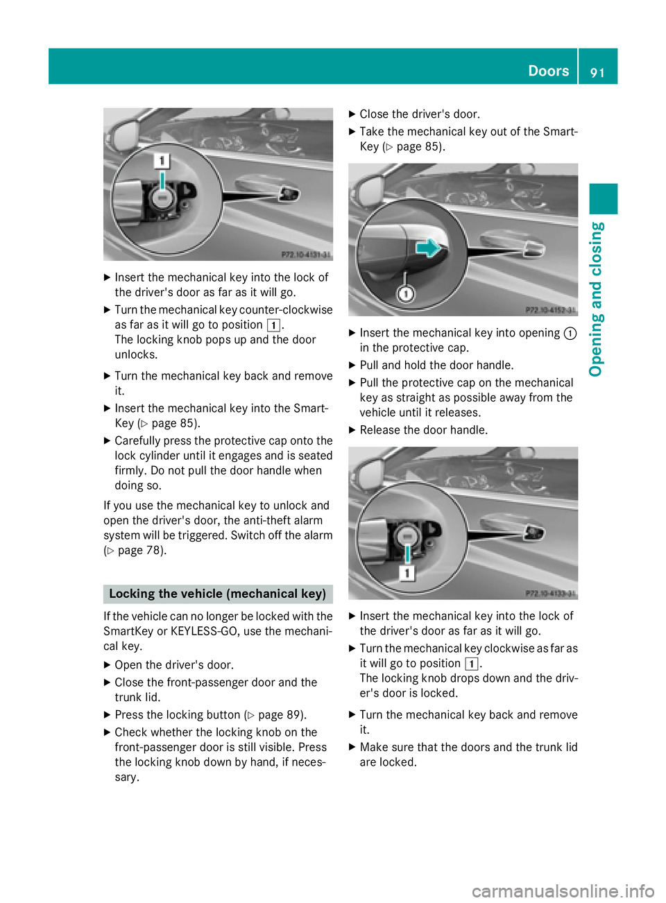
XInsert the mechanical key into the lock of
the driver's door as far as it will go.
XTurn the mechanical key counter-clockwise
as far as it will go to position 1.
The locking knob pops up and the door
unlocks.
XTurn the mechanical key back and remove
it.
XInsert the mechanical key into the Smart-
Key (
Ypage 85).
XCarefully press the protective cap onto the
lock cylinder until it engages and is seated
firmly. Do not pull the door handle when
doing so.
If you use the mechanical key to unlock and
open the driver's door, the anti-theft alarm
system will be triggered. Switch off the alarm
(
Ypage 78).
Locking the vehicle (mechanical key)
If the vehicle can no longer be locked with the SmartKey or KEYLESS-GO, use the mechani-
cal key.
XOpen the driver's door.
XClose the front-passenger door and the
trunk lid.
XPress the locking button (Ypage 89).
XCheck whether the locking knob on the
front-passenger door is still visible. Press
the locking knob down by hand, if neces-
sary.
XClose the driver's door.
XTake the mechanical key out of the Smart-
Key (
Ypage 85).
XInsert the mechanical key into opening :
in the protective cap.
XPull and hold the door handle.
XPull the protective cap on the mechanical
key as straight as possible away from the
vehicle until it releases.
XRelease the door handle.
XInsert the mechanical key into the lock of
the driver's door as far as it will go.
XTurn the mechanical key clockwise as far as
it will go to position 1.
The locking knob drops down and the driv-
er's door is locked.
XTurn the mechanical key back and remove
it.
XMake sure that the doors and the trunk lid
are locked.
Doors91
Opening and closing
Z
Page 99 of 410
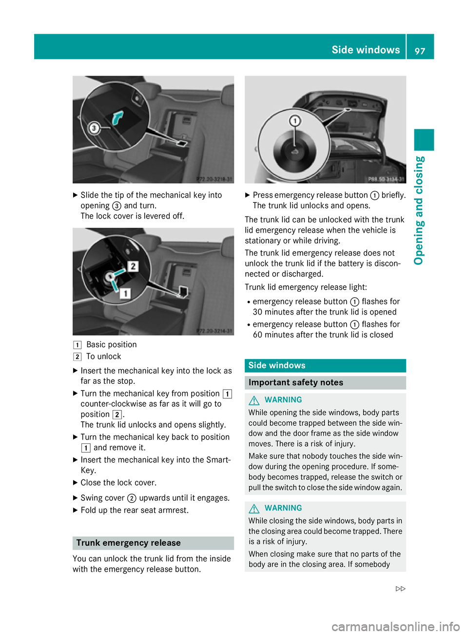
XSlide the tip of the mechanical key into
opening=and turn.
The lock cover is levered off.
1Basic position
2To unlock
XInsert the mechanical key into the lock as
far as the stop.
XTurn the mechanical key from position 1
counter-clockwise as far as it will go to
position 2.
The trunk lid unlocks and opens slightly.
XTurn the mechanical key back to position
1 and remove it.
XInsert the mechanical key into the Smart-
Key.
XClose the lock cover.
XSwing cover ;upwards until it engages.
XFold up the rear seat armrest.
Trunk emergency release
You can unlock the trunk lid from the inside
with the emergency release button.
XPress emergency release button :briefly.
The trunk lid unlocks and opens.
The trunk lid can be unlocked with the trunk
lid emergency release when the vehicle is
stationary or while driving.
The trunk lid emergency release does not
unlock the trunk lid if the battery is discon-
nected or discharged.
Trunk lid emergency release light:
Remergency release button :flashes for
30 minutes after the trunk lid is opened
Remergency release button :flashes for
60 minutes after the trunk lid is closed
Side windows
Important safety notes
GWARNING
While opening the side windows, body parts
could become trapped between the side win-
dow and the door frame as the side window
moves. There is a risk of injury.
Make sure that nobody touches the side win-
dow during the opening procedure. If some-
body becomes trapped, release the switch or
pull the switch to close the side window again.
GWARNING
While closing the side windows, body parts in
the closing area could become trapped. There is a risk of injury.
When closing make sure that no parts of the
body are in the closing area. If somebody
Side windows97
Opening and closing
Z
Page 149 of 410
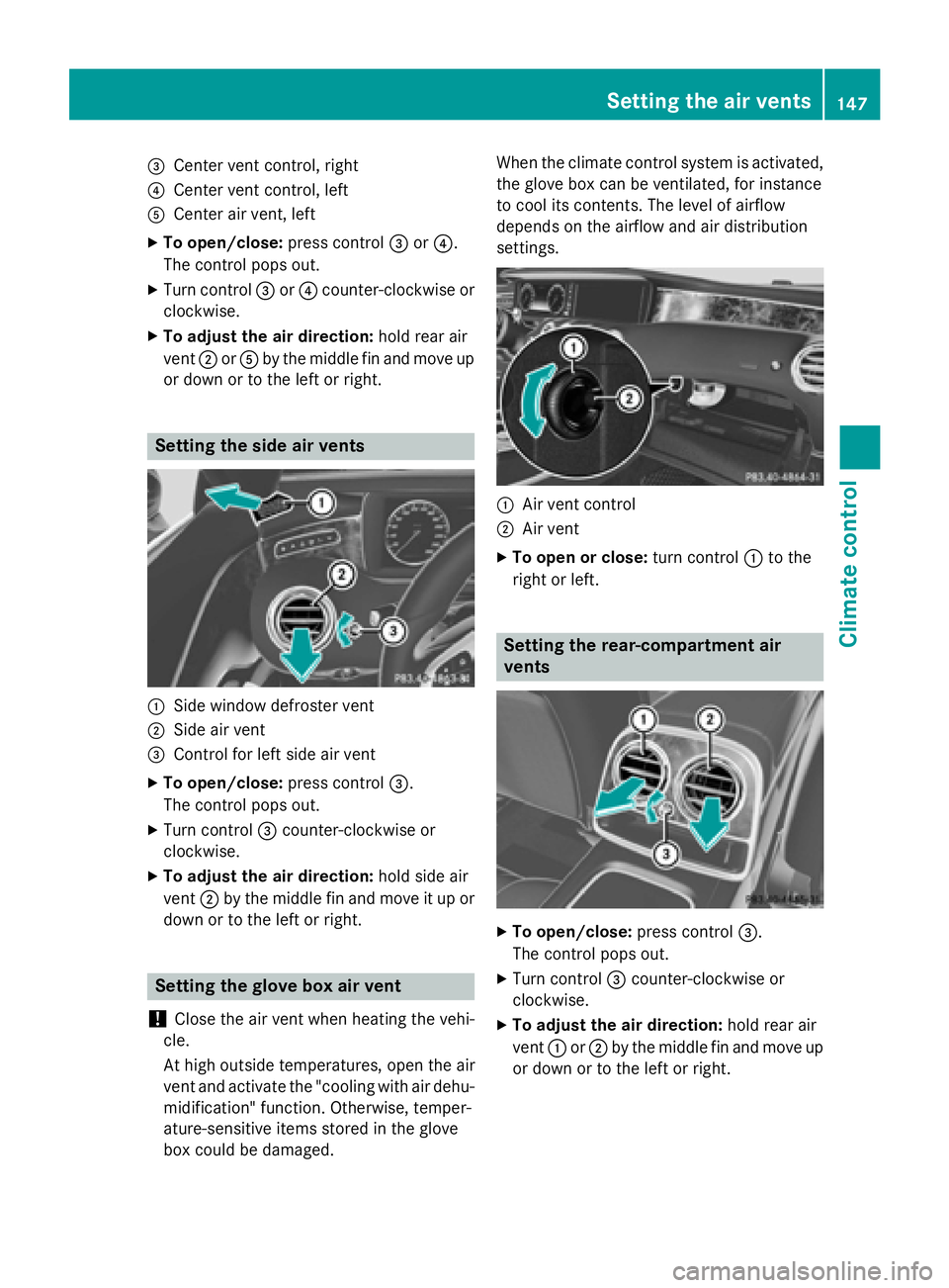
=Center vent control, right
?Center vent control, left
ACenter air vent, left
XTo open/close:press control=or?.
The control pops out.
XTurn control =or? counter-clockwise or
clockwise.
XTo ad just the air direction: hold rear air
vent ;orA by the midd lefin and move up
or down or to the left or right.
Setting the side air vents
:Sidewin dow defroster vent
;Side air vent
=Control for left side air vent
XTo open/close: press control=.
The control pops out.
XTurn control =counter-clockwise or
clockwise.
XTo ad just the air direction: holdsideair
vent ;bythe midd lefin and move it up or
down or to the left or right.
Setting the glove box air vent
!
Close the air vent when heating the veh i-
cle.
At high outside temperatures, open the air
vent and activate the "cooling with air dehu- midi fication" function. Otherwise, temper-
ature-sensitive items stored inthe glove
box could bedamaged. When the climate control system
isactivated,
the glove box can beventilated, for instance
to cool its contents. The level of airflow
depends on the airflow and air distribution
settings.
:Air vent control
;Air vent
XTo open orclose: turn control :to the
right or left.
Setting the rear-compartment air
vents
XTo open/close: press control=.
The control pops out.
XTurn control =counter-clock wiseor
clockwise.
XTo ad just the air direction: hold rear air
vent :or; bythe midd lefin and move up
or down or to the left or right.
Setting the air vents147
Climate control
Z
Page 171 of 410
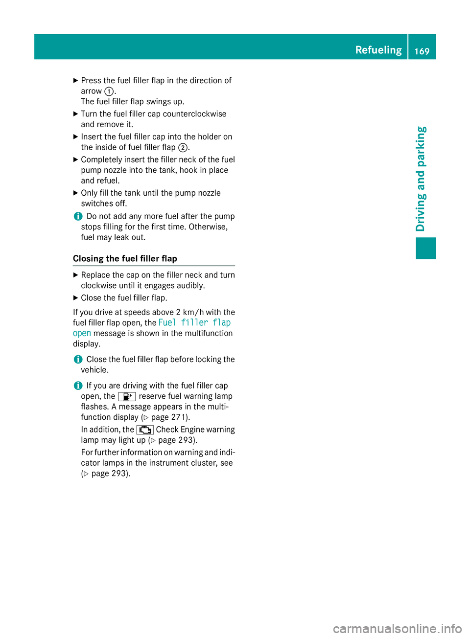
XPress the fuel filler flap in the direction of
arrow:.
The fuel filler flap swings up.
XTurn the fuel filler cap counterclockwise
and remove it.
XInsert the fuel filler cap into the holder on
the inside of fuel filler flap ;.
XCompletely insert the filler neck of the fuel
pump nozzle into the tank, hook in place
and refuel.
XOnly fill the tank until the pump nozzle
switches off.
iDo not add any more fuel after the pump
stops filling for the first time. Otherwise,
fuel may leak out.
Closing the fuel filler flap
XReplace the cap on the filler neck and turn
clockwise until it engages audibly.
XClose the fuel filler flap.
If you drive at speeds above 2 km/ hwith the
fuel filler flap open, the Fuel
fillerflap
openmessage is shown in the multifunction
display.
iClose the fuel filler flap before locking the
vehicle.
iIf you are driving with the fuel filler cap
open, the 8reserve fuel warning lamp
flashes. A message appears in the multi-
function display (
Ypage 271).
In addition, the ;Check Engine warning
lamp may light up (
Ypage 293).
For further information on warning and indi-
cator lamps in the instrument cluster, see
(
Ypage 293).
Refueling169
Driving and parking
Z
Page 232 of 410
Useful information
i
This Operator's Manual describes all
models and all standard and optional equip-
ment of your vehicle available at the time of
publication of the Operator's Manual.
Country-specific differences are possible.
Please note that your vehicle may not be
equipped with all features described. This
also applies to safety-related systems and
functions.
iRead the information on qualified special-
ist workshops (
Ypage 26).
Important safety notes
GWARNING
If you operate information systems and com-
munication equipment integrated in the vehi-
cle while driving, you will be distracted from
traffic conditions. You could also lose control
of the vehicle. There is a risk of an accident.
Only operate the equipment when the traffic
situation permits. If you are not sure that this
is possible, park the vehicle paying attention
to traffic conditions and operate the equip-
ment when the vehicle is stationary.
You must observe the legal requirements for
the country in which you are currently driving
when operating the on-board computer.
GWARNING
If the instrument cluster has failed or mal-
functioned, you may not recognize function
restrictions in systems relevant to safety. The
operating safety of your vehicle may be
impaired. There is a risk of an accident.
Pull over as soon as it is safe to do so and
consult a qualified specialist workshop.
GWARNING
If the instrument cluster has failed or mal-
functioned, you may not recognize function
restrictions in systems relevant to safety. The
operating safety of your vehicle may be
impaired. There is a risk of an accident.
Drive on carefully. Have the vehicle checked
at a qualified specialist workshop immedi-
ately.
If the operating safety of your vehicle is
impaired, pull over as soon as it is safe to do
so. Contact a qualified specialist workshop.
The on-board computer only shows messages
or warnings from certain systems in the mul-
tifunction display. You should therefore make
sure your vehicle is operating safely at all
times.
For an overview, see the instrument panel
illustration (
Ypage 33).
Displays and operation
Instrument cluster lighting
The light sensor in the instrument cluster
automatically controls the brightness of the
multifunction display. In daylight, the displays in the instrument cluster are illuminated. A
dimming function is not possible in daylight.
The lighting in the instrument cluster, in the
displays and the controls in the vehicle inte-
rior can be adjusted using the brightness con-
trol knob.
The brightness control is located between the
instrument cluster and the COMAND Display
(
Ypage 35).
XTurn the brightness control knob clockwise
or counter-clockwise.
If the light switch (
Ypage 126) is set to
Ã, TorL, the brightness is
dependent upon the brightness of the
ambient light.
Tachometer
!
Do not drive in the overrevving range, as
this could damage the engine.
230Displays and operation
On-board computer and displays
Page 303 of 410
RClose lockablestowage compartments
while driv ing.
RStow and secure objects that are heavy,
hard, pointy, sharp-edged, fragile or too
large inthe trunk.
Observe the loading guidelines (Ypage 300).
Stowage compartments in the front
Glove box
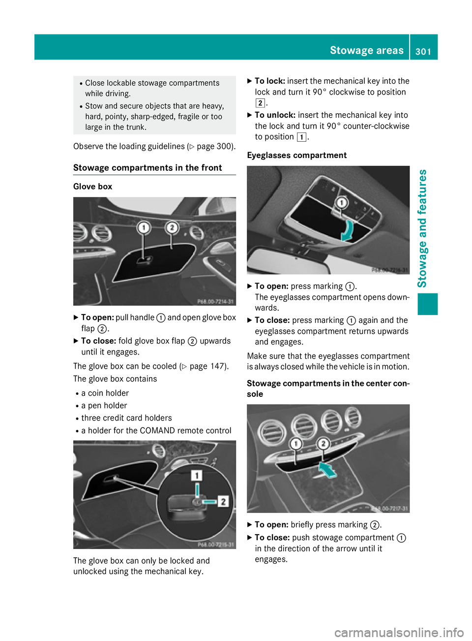
XTo open: pull handle :and open glove box
flap ;.
XTo close: fold glove box flap ;upwards
until it engages.
The glove box can be cooled (
Ypage 147).
The glove box contains
Ra coin holder
Ra pen holder
Rthree credit card holders
Ra holder for the COMAND remote control
The glove box can only be locked and
unlocked using the mechanical key.
XTo lock: insert the mechanical key into the
lock and turn it 90° clockwise to position
2.
XTo unlock: insert the mechanical key into
the lock and turn it 90° counter-clockwise
to position 1.
Eyeglasses compartment
XTo open: press marking :.
The eyeglasses compartment opens down- wards.
XTo close: press marking :again and the
eyeglasses compartment returns upwards
and engages.
Make sure that the eyeglasses compartment
is always closed while the vehicle is in motion.
Stowage compartments in the center con-
sole
XTo open: briefly press marking ;.
XTo close:push stowage compartment :
in the direction of the arrow until it
engages.
Stowage areas301
Stowage and features
Z
Page 330 of 410
Where possible, let the engine cool down andtouch only the components described in the
following.
GWARNING
If engine oil comes into contact with hot com- ponents in the engine compartment, it may
ignite. There is a risk of fire and injury.
Make sure that engine oil is not spilled next to
the filler neck. Let the engine cool down and
thoroughly clean the engine oil off the com-
ponents before starting the engine.
HEnvironmental note
When adding oil, take care not to spill any. If
oil enters the soil or waterways, it is harmful to
the environment.
!Only use engine oils and oil filters that
have been approved for vehicles with a ser-
vice system. You can obtain a list of the
engine oils and oil filters tested and
approved in accordance with the
Mercedes-Benz Specifications for Service
Products at any Mercedes-Benz Service
center.
Damage to the engine or exhaust system is
caused by the following:
Rusing engine oils and oil filters that have
not been specifically approved for the
service system
Rreplacing engine oil and oil filters after
the interval for replacement specified by the service system has been exceeded
Rusing engine oil additives.
!Do not add too much oil. adding too much
engine oil can result in damage to the
engine or to the catalytic converter. Have
excess engine oil siphoned off.
Example
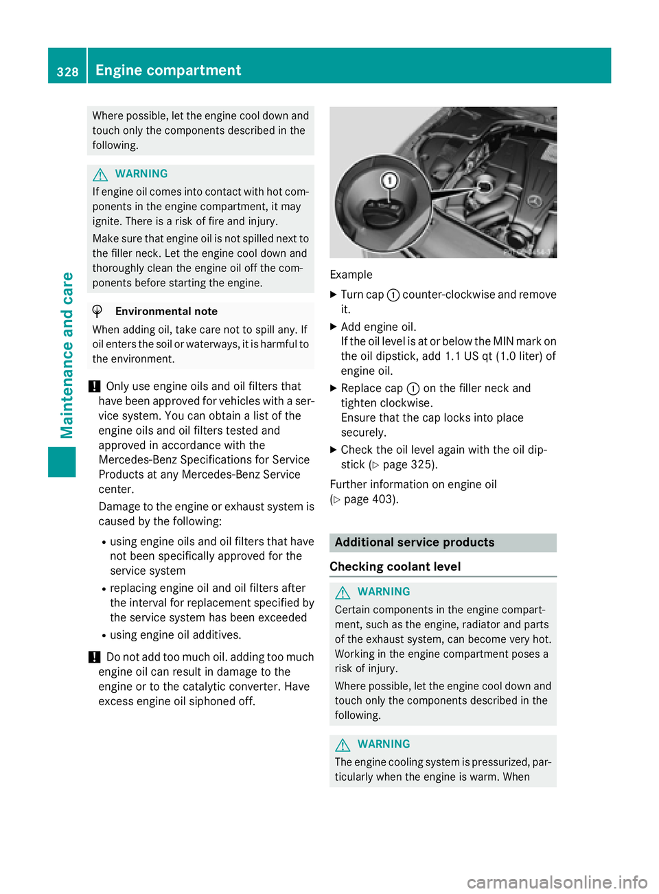
XTurn cap :counter-clockwise and remove
it.
XAdd engine oil.
If the oil level is at or below the MIN mark on
the oil dipstick, add 1.1 US qt (1.0 liter) of
engine oil.
XReplace cap :on the filler neck and
tighten clockwise.
Ensure that the cap locks into place
securely.
XCheck the oil level again with the oil dip-
stick (
Ypage 325).
Further information on engine oil
(
Ypage 403).
Additional service products
Checking coolant level
GWARNING
Certain components in the engine compart-
ment, such as the engine, radiator and parts
of the exhaust system, can become very hot.
Working in the engine compartment poses a
risk of injury.
Where possible, let the engine cool down and touch only the components described in the
following.
GWARNING
The engine cooling system is pressurized, par-
ticularly when the engine is warm. When
328Engine compartment
Maintenance and care
Page 331 of 410
opening the cap, you could be scalded by hot
coolant spraying out. There is a risk of injury.Let the engine cool down before opening the
cap. Wear eye and hand protection when
opening the cap. Open the cap slowly half a
turn to allow pressure to escape.
XPark the vehicle on a level surface.
Only check the coolant level when the vehi-
cle is on a level surface and the engine has
cooled down.
XTurn the SmartKey to position 2in the igni-
tion lock (
Ypage 151).
or
XPress Start/Stop button twice
(
Ypage 151).
XCheck the coolant temperature display in
the instrument cluster.
The coolant temperature must be below
158 ‡ (70 †).
XTurn the SmartKey to position
0 (
Ypage 151) in the ignition lock.
or
XRemove Start/Stop button from ignition
lock (
Ypage 151).
XSlowly turn cap :half a turn counter-
clockwise and allow excess pressure to
escape.
XTurn cap :further counter-clockwise and
remove it.
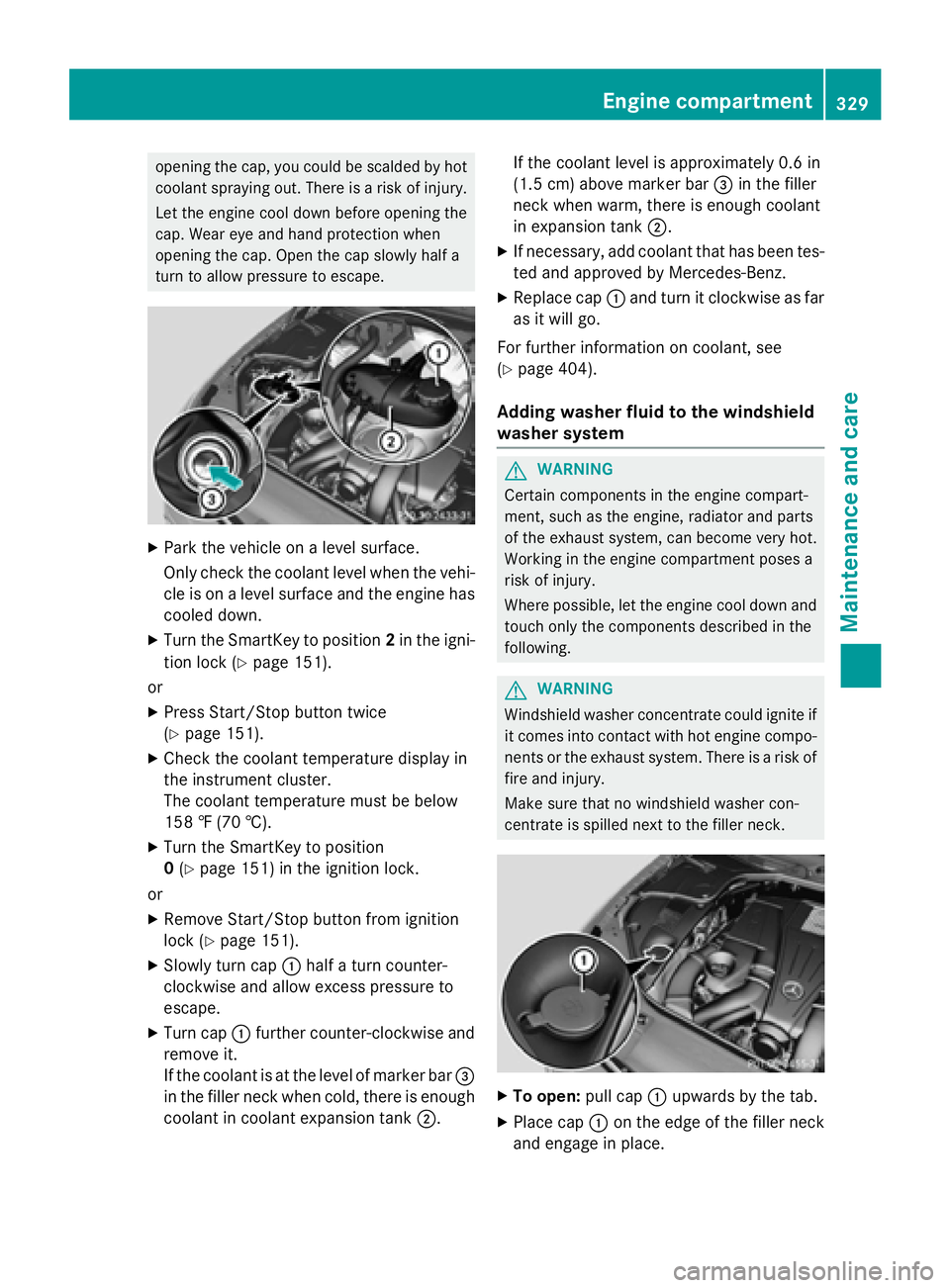
If the coolant is at the level of marker bar =
in the filler neck when cold, there is enough
coolant in coolant expansion tank ;.If the coolant level is approximately 0.6 in
(1.5 cm) above marker bar
=in the filler
neck when warm, there is enough coolant
in expansion tank ;.
XIf necessary, add coolant that has been tes-
ted and approved by Mercedes-Benz.
XReplace cap:and turn it clockwise as far
as it will go.
For further information on coolant, see
(
Ypage 404).
Adding washer fluid to the windshield
washer system
GWARNING
Certain components in the engine compart-
ment, such as the engine, radiator and parts
of the exhaust system, can become very hot.
Working in the engine compartment poses a
risk of injury.
Where possible, let the engine cool down and touch only the components described in the
following.
GWARNING
Windshield washer concentrate could ignite if it comes into contact with hot engine compo-
nents or the exhaust system. There is a risk of
fire and injury.
Make sure that no windshield washer con-
centrate is spilled next to the filler neck.
XTo open: pull cap:upwards by the tab.
XPlace cap :on the edge of the filler neck
and engage in place.
Engine compartment329
Maintenance and care
Z
Page 357 of 410

If the automatic transmission cannot be shif-
ted to positionN, have the vehicle transpor-
ted on a transporter or trailer.
The battery must be connected and charged.
Otherwise, you:
Rcannot turn the SmartKey to position 2in
the ignition lock
Rcannot release the electric parking brake
Rcannot shift the automatic transmission to position N
iDeactivate the automatic locking feature
(
Ypage 90). You could otherwise be locked
out when pushing or towing the vehicle.
Installing/removing the towing eye
Installing the towing eye
The brackets for the screw-in towing eyes are
located in the bumpers. They are at the front
and at the rear under covers :.
XRemove the towing eye from the vehicle
tool kit/stowage tray (
Ypage 342).
XPress the mark on cover:inwards in the
direction of the arrow.
XRemove cover :from the opening.
XScrew in the towing eye clockwise as far as
it will go and tighten it.
Removing the towing eye
XUnscrew and remove the towing eye.
XAttach cover :to the bumper and press
until it engages.
XPlace the towing eye in the vehicle tool kit/
stowage tray.
Towing a vehicle with both axles on
the ground
It is important that you observe the safety
instructions when towing away your vehicle
(
Ypage 354).
The automatic transmission automatically
shifts to position Pwhen you open the driver's
or front-passenger door or when you remove
the SmartKey from the ignition lock.
In order to ensure that the automatic trans-
mission stays in position Nwhen towing the
vehicle, you must observe the following
points:
XYou must use the SmartKey instead of the
Start/Stop button (
Ypage 151).
XMake sure that the vehicle is stationary and
the SmartKey in the ignition lock is in posi-
tion 0.
XTurn the SmartKey to position 2in the igni-
tion lock.
XDepress and hold the brake pedal.
XShift the automatic transmission to posi-
tion N.
XRelease the brake pedal.
XRelease the electric parking brake.
XLeave the SmartKey in position 2in the
ignition lock.
XSwitch on the hazard warning lamps
(
Ypage 126).
iIn order to signal a change of direction
when towing the vehicle with the hazard
warning lamps switched on, use the com-
bination switch as usual. In this case, only
the indicator lamps for the direction of
travel flash. After resetting the combina-
Towing and tow-starting355
Breakdown assistance
Z
Page 388 of 410
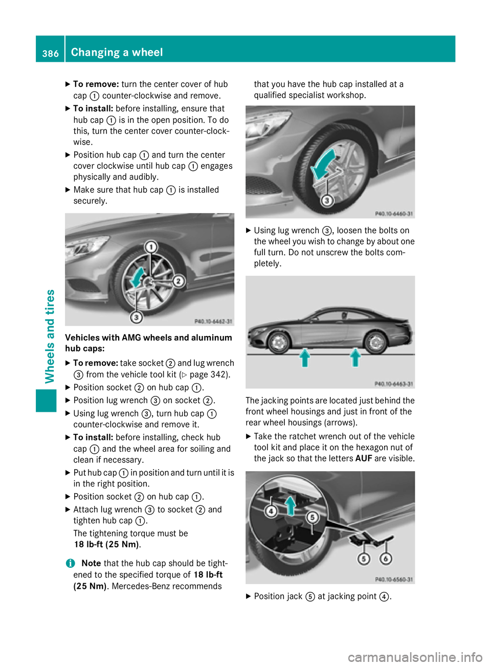
XTo remove:turn the center cover of hub
cap :counter-clockwise and remove.
XTo install: before installing, ensure that
hub cap :is in the open position. To do
this, turn the center cover counter-clock-
wise.
XPosition hub cap :and turn the center
cover clockwise until hub cap :engages
physically and audibly.
XMake sure that hub cap :is installed
securely.
Vehicles with AMG wheels and aluminum
hub caps:
XTo remove: take socket;and lug wrench
= from the vehicle tool kit (
Ypage 342).
XPosition socket ;on hub cap :.
XPosition lug wrench =on socket ;.
XUsing lug wrench =, turn hub cap:
counter-clockwise and remove it.
XTo install: before installing, check hub
cap :and the wheel area for soiling and
clean if necessary.
XPut hub cap :in position and turn until it is
in the right position.
XPosition socket ;on hub cap :.
XAttach lug wrench =to socket ;and
tighten hub cap :.
The tightening torque must be
18 lb-ft (25 Nm) .
iNotethat the hub cap should be tight-
ened to the specified torque of 18 lb-ft
(25 Nm) . Mercedes-Benz recommends that you have the hub cap installed at a
qualified specialist workshop.
XUsing lug wrench
=, loosen the bolts on
the wheel you wish to change by about one
full turn. Do not unscrew the bolts com-
pletely.
The jacking points are located just behind the
front wheel housings and just in front of the
rear wheel housings (arrows).
XTake the ratchet wrench out of the vehicle
tool kit and place it on the hexagon nut of
the jack so that the letters AUFare visible.
XPosition jack Aat jacking point ?.
386Changing a wheel
Wheels and tires