change wheel MERCEDES-BENZ SL CLASS 2011 Owners Manual
[x] Cancel search | Manufacturer: MERCEDES-BENZ, Model Year: 2011, Model line: SL CLASS, Model: MERCEDES-BENZ SL CLASS 2011Pages: 316, PDF Size: 6.55 MB
Page 19 of 316

Messages in the multifunction
display ........................................... 253
Replacing bulbs ............................. 272
U
Uniform Tire Quality Grading
Standards .................................. 199, 207
Units
Selecting digital speedometer
display mode ................................. 123
Selecting speedometer/
odometer display mode .................123
Unleaded gasoline, premium ........... 306
Unlocking the vehicle
KEYLESS-GO .................................... 69
Manually ........................................ 267
SmartKey ......................................... 68
Upholstery, cleaning ......................... 221
Useful features .................................. 164
V
Valet locking ........................................ 77
Vehicle
Battery ........................................... 283
Care ............................................... 215
Control system .............................. 113
Identification Number (VIN) ...........294
Locking/unlocking ........................... 68
Lowering (wheel change) ...............282
Modifications and alterations,
Operating safety .............................. 21
Towing ........................................... 287
Unlocking/locking manually ..........267
Vehicle dimensions
see Vehicle specification
Vehicle Identification Number
(VIN) ................................................... 294
Vehicle jack see Jack
Vehicle lighting .................................... 89
Vehicle loading
Load limit ....................................... 195
Terminology ................................... 205
Vehicle maximum load on the tire ... 207
Vehicle specification
SL 550 ........................................... 296
SL 600 ........................................... 296
SL 63 AMG .................................... 297
SL 65 AMG .................................... 298
Vehicle status message memory .... 120
Vehicle tool kit .................................. 224
Vehicle washing see Vehicle care
Vehicle weights
see Vehicle specification
W
Warning lamps see Lamps, Indicator and warning
Warning sounds
Distance warning function .............140
Distronic ........................................ 135
Driver’s or passenger’s seat belt .....48
Parking brake ................................ 239
Parktronic system ..........................147
Seat belt telltale ............................ 256
Warranty coverage ............................ 294
Washer and headlamp cleaning
system ................................................ 309
Washer fluid
Messages in the multifunction
display ........................................... 243
Mixing ratio .................................... 309
Refilling .......................................... 185
Washing the vehicle .......................... 215
Wear pattern (tires) .......................... 200
Weights (vehicle) see Vehicle specification
Wheel
Changing ....................................... 276
Removing ....................................... 279
Spare ............................................. 276
Tightening torque ........................... 282
Wheels, sizes ..................................... 299
Wheels, Tires and .............................. 186
Windows see Power windows
Windows, cleaning ............................ 219
Wind screen ....................................... 157
Index17230_AKB; 6; 22, en-USd2ureepe,Version: 2.11.8.12009-07-28T18:49:58+02:00 - Seite 17
Page 43 of 316
installed or supplied by an authorized
Mercedes-Benz Center.
RAir bags and pyrotechnic Emergency
Tensioning Devices (ETDs) contain
perchlorate material, which may require
special handling and regard for the
environment. Check with your local
government’s disposal guidelines.
California residents, see
www.dtsc.ca.gov/HazardousWaste/
Perchlorate/index.cfm.
RAir bags and ETDs are designed to function
on a one-time-only basis. An air bag or ETD
that has deployed must be replaced.
RDo not pass seat belts over sharp edges.
They could tear.
RDo not make any modification that could
change the effectiveness of the seat belts.
RDo not bleach or dye seat belts as this may
severely weaken them. In a crash they may
not be able to provide adequate protection.
RNo modifications of any kind may be made
to any components or wiring of the SRS.
RDo no change or remove any component or
part of the SRS.
RDo not install additional trim material, seat
covers, badges, etc. over the steering
wheel hub, passenger front air bag cover,
outboard sides of the seat backrests, door
trim panels, or door frame trims.
RDo not install additional electrical/
electronic equipment on or near SRS
components and wiring.
RKeep area between air bags and occupants
free of objects (e.g. packages, purses,
umbrellas, etc.).
RAir bag system components will be hot after
an air bag has inflated. Do not touch them.
RNever place your feet on the instrument
panel, dashboard, or on the seat. Always
keep both feet on the floor in front of the
seat.
RImproper repair work on the SRS creates a
risk of rendering the SRS inoperative or
causing unintended air bag deployment.
Work on the SRS must therefore only be
performed by qualified technicians.
Contact an authorized Mercedes-Benz
Center.
RFor your protection and the protection of
others, when scrapping the air bag unit or
ETD, our safety instructions must be
followed. These instructions are available
from any authorized Mercedes-Benz
Center.
RGiven the considerable deployment speed,
required inflation volume, and the material
of the air bags, there is the possibility of
abrasions or other, potentially more serious
injuries resulting from air bag deployment.
If you sell your vehicle, we strongly
recommend that you inform the subsequent
owner that the vehicle is equipped with SRS.
Also refer them to the applicable section in
the Operator’s Manual.
Front air bags
GObserve Safety notes, see page 39.
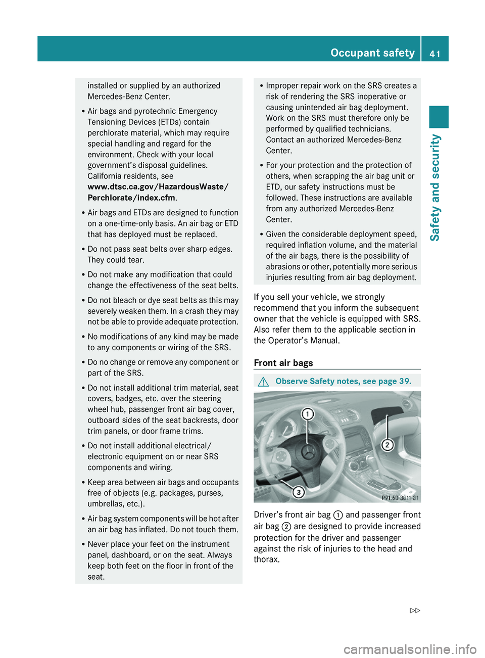
Driver’s front air bag \000F and passenger front
air bag \000G are designed to provide increased
protection for the driver and passenger
against the risk of injuries to the head and
thorax.
Occupant safety41Safety and security230_AKB; 6; 22, en-USd2ureepe,Version: 2.11.8.12009-07-28T18:49:58+02:00 - Seite 41Z
Page 54 of 316
GWarning!
When leaving the vehicle, always remove the
SmartKey from the starter switch. Always
take the SmartKey with you and lock the
vehicle. Do not leave children unattended in
the vehicle, even if they are secured in a child
restraint system, or with access to an
unlocked vehicle. A child’s unsupervised
access to a vehicle could result in an accident
and/or serious personal injury. The children
could
R injure themselves on parts of the vehicle
R be seriously or fatally injured through
excessive exposure to extreme heat or cold
R injure themselves or cause an accident with
vehicle equipment that can be operated
even if the SmartKey is removed from the
starter switch or removed from the vehicle,
such as seat adjustment, steering wheel
adjustment, or the memory function
If children open a door, they could injure other
persons or get out of the vehicle and injure
themselves or be injured by following traffic.
Do not expose the child restraint system to
direct sunlight. The child restraint system’s
metal parts, for example, could become very
hot, and the child could be burned by these
parts.
GWarning!
Do not carry heavy or hard objects in the
passenger compartment unless they are
firmly secured in place.
Unsecured or improperly positioned cargo
increases a child’s risk of injury in the event
of
R strong braking maneuvers
R sudden changes of direction
R an accident
Infant and child restraint systemsGObserve Safety notes, see page 51.
We recommend all infants and children be
properly restrained at all times while the
vehicle is in motion.
The passenger lap/shoulder belt has a
special seat belt retractor for secure
fastening of child restraints.
To fasten a child restraint, follow the child
restraint manufacturer’s instructions for
mounting.
To activate the special seat belt retractor:
XPull the shoulder belt out completely and
let it retract.
During seat belt retraction, a ratcheting
sound can be heard to indicate that the
special seat belt retractor is activated.
The seat belt is now locked.XPush down on child restraint to take up any
slack.
To deactivate the special seat belt retractor:
XRelease the seat belt buckle and let the
seat belt retract completely.
The seat belt can then again be used in the
usual manner.GWarning!
Never release the seat belt buckle while the
vehicle is in motion, since the special seat belt
retractor will be deactivated.
The use of infant or child restraints is required
by law in all 50 states, the District of
Columbia, the U.S. territories and all
Canadian provinces.
Infants and small children should be seated
in an appropriate infant or child restraint
system. They must be properly secured by a
lap/shoulder belt in accordance with the
manufacturer’s instructions for the child
restraint. All infant or child restraint systems
must comply with U.S. Federal Motor Vehicle
Safety Standards 213 and 225 and Canadian
Motor Vehicle Safety Standards 213 and
210.2.
52Occupant safetySafety and security
230_AKB; 6; 22, en-USd2ureepe,Version: 2.11.8.12009-07-28T18:49:58+02:00 - Seite 52
Page 111 of 316
reappears in the right multifunction
display.
or
XPull and hold right gearshift control \000G until
D reappears in the right multifunction
display.
The automatic transmission will shift from
the current gear range directly into drive
position D.
Shifting into optimal gear range
XPress and hold the gear selector lever to
the left in the D- direction.
or
XPull and hold left gearshift control \000F.
The automatic transmission will select the
gear range suited for optimal acceleration
and deceleration automatically. This will
involve shifting down one or more gears.
Manual shift program
The manual shift program is available on
vehicles with AMG Sport Package, SL 63 AMG
and SL 65 AMG only.
Manual program mode M differs with regard
to spontaneity, response time, and shifting
smoothness from automatic program modes
S or S+ (SL 63 AMG only).
In manual program mode M, system-
controlled automatic gearshifting is switched
off. You need to change the gears by manually
upshifting or downshifting using the gear
selector lever or the steering wheel gearshift
control.
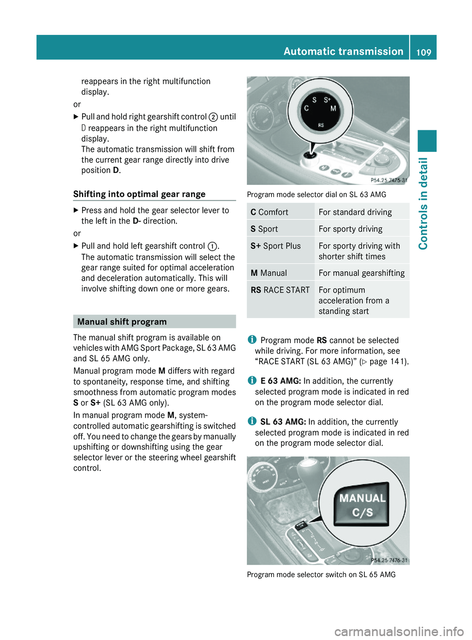
Program mode selector dial on SL 63 AMG
C ComfortFor standard drivingS SportFor sporty drivingS+ Sport PlusFor sporty driving with
shorter shift times
M ManualFor manual gearshiftingRS RACE STARTFor optimum
acceleration from a
standing start
iProgram mode RS cannot be selected
while driving. For more information, see
“RACE START (SL 63 AMG)” (Y page 141).
iE 63 AMG: In addition, the currently
selected program mode is indicated in red
on the program mode selector dial.
iSL 63 AMG: In addition, the currently
selected program mode is indicated in red
on the program mode selector dial.
Program mode selector switch on SL 65 AMG
Automatic transmission109Controls in detail230_AKB; 6; 22, en-USd2ureepe,Version: 2.11.8.12009-07-28T18:49:58+02:00 - Seite 109Z
Page 115 of 316
Doing so may cause serious engine damage
which is not covered by the Mercedes-Benz
Limited Warranty.
Resetting trip odometer
XMake sure you are viewing the standard
display (Y page 116) in the multifunction
display.
XPress and hold the reset button in the
instrument cluster (Y page 111) until the
trip odometer is reset.
Tachometer
The red marking on the tachometer
(Y page 30) denotes excessive engine speed.
! Avoid driving at excessive engine speeds,
as it may result in serious engine damage
that is not covered by the Mercedes-Benz
Limited Warranty.
To help protect the engine, the fuel supply is
interrupted if the engine is operated within
the red marking.
Control system
Introduction
The control system is activated as soon as the
starter switch is in position 1.
The control system enables you to call up
information about your vehicle and to change
vehicle settings.
For example, you can use the control system
to find out when your vehicle is next due for
maintenance service, to set the language for
messages in the instrument cluster display,
and much more.
GWarning!
A driver’s attention to the road and traffic
conditions must always be his/her primary
focus when driving.
For your safety and the safety of others,
selecting features through the multifunction
steering wheel should only be done by the
driver when traffic and road conditions permit
it to be done safely.
Bear in mind that at a speed of just 30 mph
(approximately 50 km/h), your vehicle is
covering a distance of 44 feet (approximately
14 m) every second.
The control system relays information to the
multifunction display.
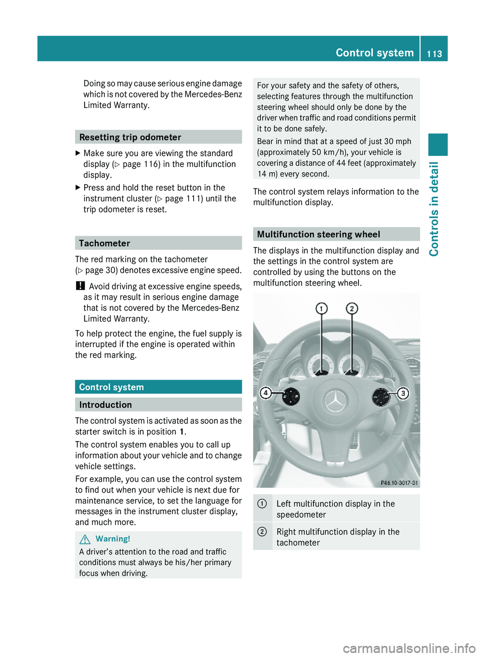
Multifunction steering wheel
The displays in the multifunction display and
the settings in the control system are
controlled by using the buttons on the
multifunction steering wheel.
\000FLeft multifunction display in the
speedometer
\000GRight multifunction display in the
tachometer
Control system113Controls in detail230_AKB; 6; 22, en-USd2ureepe,Version: 2.11.8.12009-07-28T18:49:58+02:00 - Seite 113Z
Page 135 of 316
XBriefly pull the cruise control lever in
direction of arrow 0088.
If no speed is stored, the current speed is
set and stored.XRemove your foot from the accelerator
pedal.
The last stored speed is deleted from memory
when the engine is turned off.
Distronic
Safety notes
When activated, the Distronic adaptive cruise
control increases the driving convenience
afforded by the cruise control while traveling
on expressways and other major roadways.
R If the Distronic distance sensor detects a
slower moving vehicle directly ahead, your
vehicle speed will be reduced so that you
follow that vehicle at your preset following
distance.
R If there is no vehicle directly ahead of you,
the Distronic will function in the same way
as standard cruise control ( Y page 130).
GWarning!
The Distronic requires familiarity with its
operational characteristics. We strongly
recommend that you review the following
information carefully before operating the
system.
GWarning!
The Distronic is a convenience system. Its
speed adjustment reduction capability is
intended to make cruise control more
effective and usable when traffic speeds vary.
It is not however, intended to, nor does it,
replace the need for extreme care.
The responsibility for the vehicle’s speed,
distance to the preceding vehicle and, most
importantly, brake operation to ensure a safe
stopping distance, always remains with the
driver.
The Distronic cannot take street and traffic
conditions into account. Complex driving
situations are not always fully recognized by
the Distronic. This could result in wrong or
missing distance warnings.GWarning!
The Distronic adaptive cruise control is not a
substitute for active driving involvement. It
does not react to pedestrians or on stationary
objects, nor does it recognize or predict the
lane curvature or the movement of preceding
vehicles.
The Distronic can only apply 20% of the
maximum braking power of the vehicle.
It is the driver’s responsibility at all times to
be attentive to the road, weather and traffic
conditions. Additionally, the driver must
provide the steering, braking and other driving
inputs necessary to remain in control of the
vehicle.
High-frequency sources such as toll stations,
speed measuring systems etc. can cause the
Distronic system to malfunction.
GWarning!
The Distronic cannot take road and traffic
conditions into account. Only use the
Distronic if the road, weather and traffic
conditions make it advisable to travel at a
constant speed.
GWarning!
Use of the Distronic can be dangerous on
slippery roads. Rapid changes in tire traction
can result in wheel spin and loss of control.
The Distronic does not function in adverse
sight and distance conditions. Do not use the
Distronic during conditions of fog, heavy rain,
snow or sleet.
Driving systems133Controls in detail230_AKB; 6; 22, en-USd2ureepe,Version: 2.11.8.12009-07-28T18:49:58+02:00 - Seite 133Z
Page 145 of 316
The vehicle chassis ride height is raised or
lowered according to the selected level
setting and to the vehicle speed. With
increasing speed, the ride height is reduced
by up to approximately 0.5 in (12 mm). With
decreasing speed, the ride height is again
raised to the selected vehicle level.
These height adjustments are so small that
you may not notice any change.
Setting the vehicle level
GWarning!
To help avoid personal injury, keep hands and
feet away from wheel housing area, and stay
away from under the vehicle when lowering
the vehicle chassis.
The following vehicle level settings can be
selected when the vehicle is stationary and
the engine is running:
LevelUse forIndicator
lamps
NormalFor driving on
normal roads.
Both lamps
are off.
Level 1For driving on
rough roads or
with snow chains
(Y page 208).
One lamp
is on.
Level 2For driving on very
rough road surface
conditions.
Both lamps
are on.
Select the level 1 and level 2 settings only
when required by current driving conditions.
Otherwise the fuel consumption may
increase and/or the handling may be
impaired.
iThe selected setting remains stored in
memory, even when the engine is turned
off and restarted.
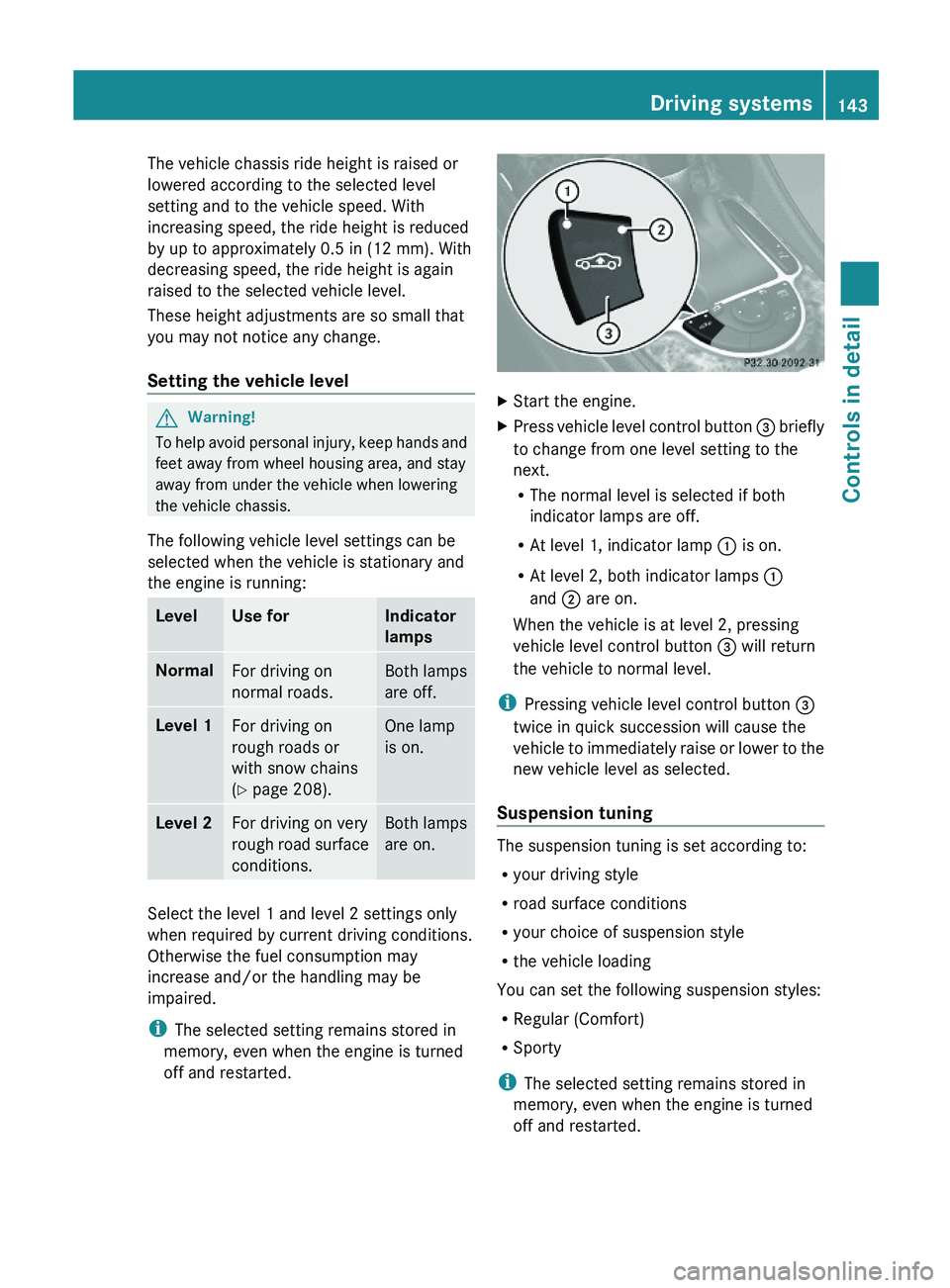
XStart the engine.XPress vehicle level control button \000
Page 171 of 316
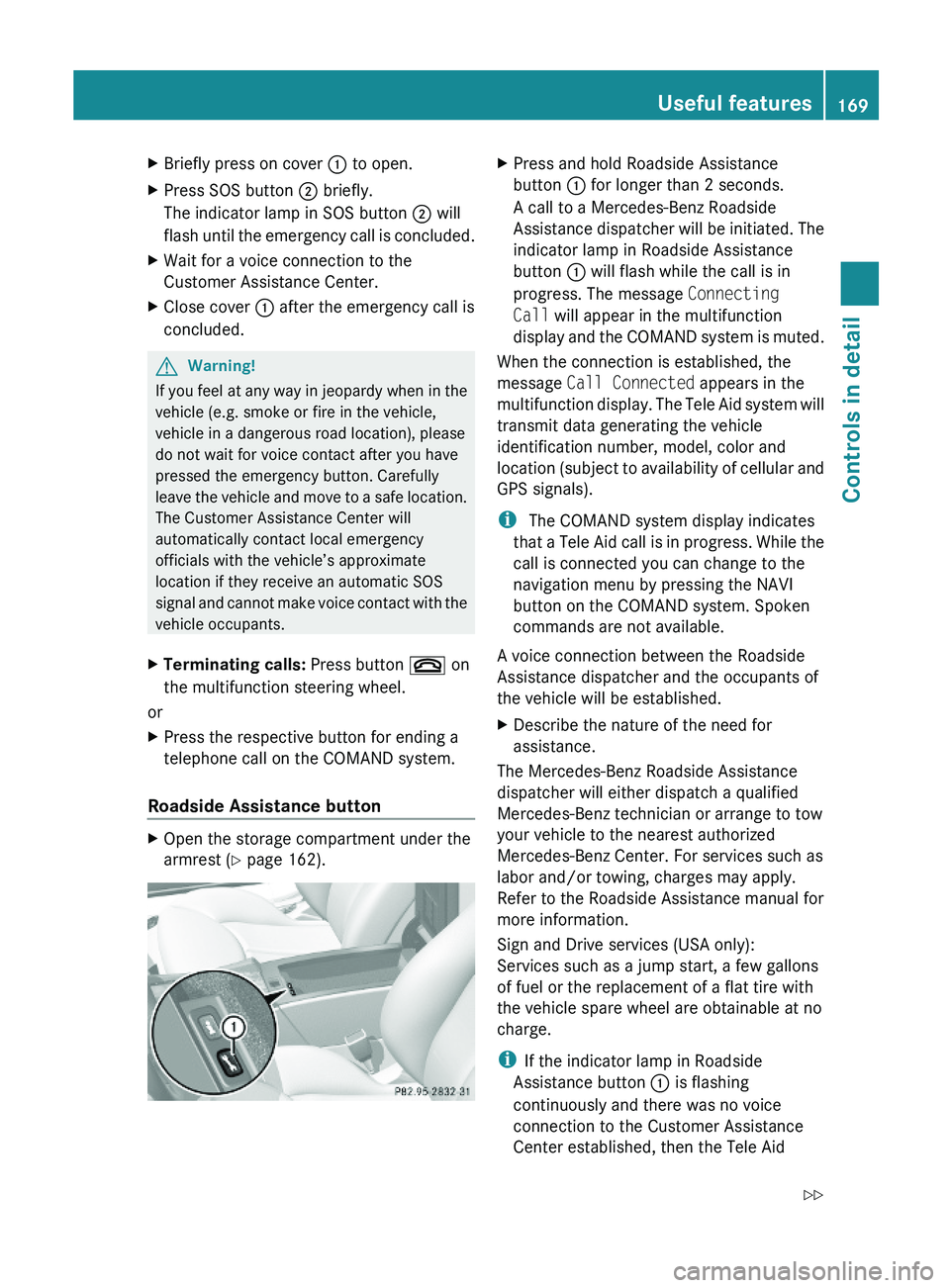
XBriefly press on cover \000F to open.XPress SOS button \000G briefly.
The indicator lamp in SOS button \000G will
flash until the emergency call is concluded.
XWait for a voice connection to the
Customer Assistance Center.
XClose cover \000F after the emergency call is
concluded.
GWarning!
If you feel at any way in jeopardy when in the
vehicle (e.g. smoke or fire in the vehicle,
vehicle in a dangerous road location), please
do not wait for voice contact after you have
pressed the emergency button. Carefully
leave the vehicle and move to a safe location.
The Customer Assistance Center will
automatically contact local emergency
officials with the vehicle’s approximate
location if they receive an automatic SOS
signal and cannot make voice contact with the
vehicle occupants.
XTerminating calls: Press button \000 on
the multifunction steering wheel.
or
XPress the respective button for ending a
telephone call on the COMAND system.
Roadside Assistance button
XOpen the storage compartment under the
armrest (Y page 162).
XPress and hold Roadside Assistance
button \000F for longer than 2 seconds.
A call to a Mercedes-Benz Roadside
Assistance dispatcher will be initiated. The
indicator lamp in Roadside Assistance
button \000F will flash while the call is in
progress. The message Connecting
Call will appear in the multifunction
display and the COMAND system is muted.
When the connection is established, the
message Call Connected appears in the
multifunction display. The Tele Aid system will
transmit data generating the vehicle
identification number, model, color and
location (subject to availability of cellular and
GPS signals).
i The COMAND system display indicates
that a Tele Aid call is in progress. While the
call is connected you can change to the
navigation menu by pressing the NAVI
button on the COMAND system. Spoken
commands are not available.
A voice connection between the Roadside
Assistance dispatcher and the occupants of
the vehicle will be established.
XDescribe the nature of the need for
assistance.
The Mercedes-Benz Roadside Assistance
dispatcher will either dispatch a qualified
Mercedes-Benz technician or arrange to tow
your vehicle to the nearest authorized
Mercedes-Benz Center. For services such as
labor and/or towing, charges may apply.
Refer to the Roadside Assistance manual for
more information.
Sign and Drive services (USA only):
Services such as a jump start, a few gallons
of fuel or the replacement of a flat tire with
the vehicle spare wheel are obtainable at no
charge.
iIf the indicator lamp in Roadside
Assistance button \000F is flashing
continuously and there was no voice
connection to the Customer Assistance
Center established, then the Tele Aid
Useful features169Controls in detail230_AKB; 6; 22, en-USd2ureepe,Version: 2.11.8.12009-07-28T18:49:58+02:00 - Seite 169Z
Page 172 of 316
system could not initiate a Roadside
Assistance call (e.g. the relevant cellular
phone network is not available). The
message Call Failed appears in the
multifunction display.
XTerminating calls: Press button \000 on
the multifunction steering wheel.
or
XPress the respective button for ending a
telephone call on the COMAND system.
Information button
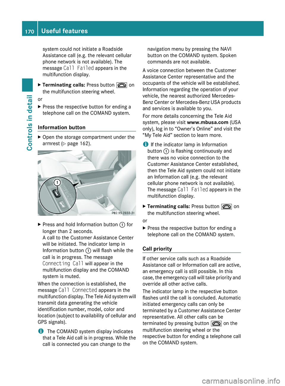
XOpen the storage compartment under the
armrest (Y page 162).
XPress and hold Information button \000F for
longer than 2 seconds.
A call to the Customer Assistance Center
will be initiated. The indicator lamp in
Information button \000F will flash while the
call is in progress. The message
Connecting Call will appear in the
multifunction display and the COMAND
system is muted.
When the connection is established, the
message Call Connected appears in the
multifunction display. The Tele Aid system will
transmit data generating the vehicle
identification number, model, color and
location (subject to availability of cellular and
GPS signals).
i The COMAND system display indicates
that a Tele Aid call is in progress. While the
call is connected you can change to the
navigation menu by pressing the NAVI
button on the COMAND system. Spoken
commands are not available.
A voice connection between the Customer
Assistance Center representative and the
occupants of the vehicle will be established.
Information regarding the operation of your
vehicle, the nearest authorized Mercedes-
Benz Center or Mercedes-Benz USA products
and services is available to you.
For more details concerning the Tele Aid
system, please visit www.mbusa.com (USA
only), log in to “Owner’s Online” and visit the
“My Tele Aid” section to learn more.
iIf the indicator lamp in Information
button \000F is flashing continuously and
there was no voice connection to the
Customer Assistance Center established,
then the Tele Aid system could not initiate
an Information call (e.g. the relevant
cellular phone network is not available).
The message Call Failed appears in the
multifunction display.
XTerminating calls: Press button \000 on
the multifunction steering wheel.
or
XPress the respective button for ending a
telephone call on the COMAND system.
Call priority
If other service calls such as a Roadside
Assistance call or Information call are active,
an emergency call is still possible. In this
case, the emergency call will take priority and
override all other active calls.
The indicator lamp in the respective button
flashes until the call is concluded. Automatic
initiated emergency calls can only be
terminated by a Customer Assistance Center
representative. All other calls can be
terminated by pressing button \000 on the
multifunction steering wheel or the
respective button for ending a telephone call
on the COMAND system.
170Useful featuresControls in detail
230_AKB; 6; 22, en-USd2ureepe,Version: 2.11.8.12009-07-28T18:49:58+02:00 - Seite 170
Page 189 of 316
Recommended tire inflation pressureGWarning!
Follow recommended tire inflation pressures.
Do not underinflate tires. Underinflated tires
wear excessively and/or unevenly, adversely
affect handling and fuel economy, and are
more likely to fail from being overheated.
Do not overinflate tires. Overinflated tires can
adversely affect handling and ride comfort,
wear unevenly, increase stopping distance,
and result in sudden deflation (blowout)
because they are more likely to become
punctured or damaged by road debris,
potholes etc.
Do not overload the tires by exceeding the
specified load limit as indicated on the Tire
and Loading Information placard on the
driver’s door B-pillar. Overloading the tires
can overheat them, possibly causing a
blowout. Overloading the tires can also result
in handling or steering problems, or brake
failure.
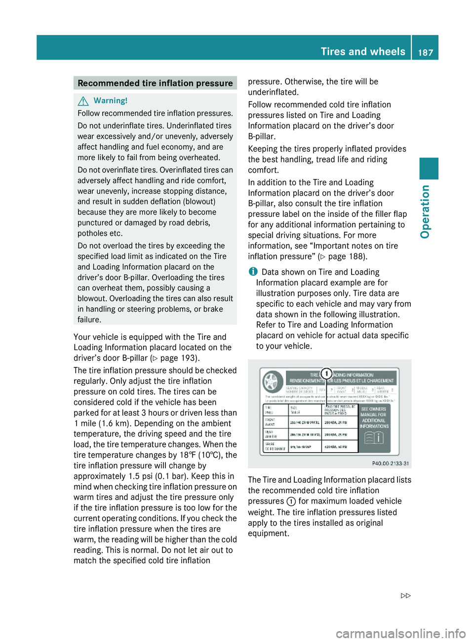
Your vehicle is equipped with the Tire and
Loading Information placard located on the
driver’s door B-pillar (Y page 193).
The tire inflation pressure should be checked
regularly. Only adjust the tire inflation
pressure on cold tires. The tires can be
considered cold if the vehicle has been
parked for at least 3 hours or driven less than
1 mile (1.6 km). Depending on the ambient
temperature, the driving speed and the tire
load, the tire temperature changes. When the
tire temperature changes by 18‡ (10†), the
tire inflation pressure will change by
approximately 1.5 psi (0.1 bar). Keep this in
mind when checking tire inflation pressure on
warm tires and adjust the tire pressure only
if the tire inflation pressure is too low for the
current operating conditions. If you check the
tire inflation pressure when the tires are
warm, the reading will be higher than the cold
reading. This is normal. Do not let air out to
match the specified cold tire inflation
pressure. Otherwise, the tire will be
underinflated.
Follow recommended cold tire inflation
pressures listed on Tire and Loading
Information placard on the driver’s door
B-pillar.
Keeping the tires properly inflated provides
the best handling, tread life and riding
comfort.
In addition to the Tire and Loading
Information placard on the driver’s door
B-pillar, also consult the tire inflation
pressure label on the inside of the filler flap
for any additional information pertaining to
special driving situations. For more
information, see “Important notes on tire
inflation pressure” (Y page 188).
iData shown on Tire and Loading
Information placard example are for
illustration purposes only. Tire data are
specific to each vehicle and may vary from
data shown in the following illustration.
Refer to Tire and Loading Information
placard on vehicle for actual data specific
to your vehicle.
The Tire and Loading Information placard lists
the recommended cold tire inflation
pressures \000F for maximum loaded vehicle
weight. The tire inflation pressures listed
apply to the tires installed as original
equipment.
Tires and wheels187Operation230_AKB; 6; 22, en-USd2ureepe,Version: 2.11.8.12009-07-28T18:49:58+02:00 - Seite 187Z