height MERCEDES-BENZ SL CLASS 2018 Owners Manual
[x] Cancel search | Manufacturer: MERCEDES-BENZ, Model Year: 2018, Model line: SL CLASS, Model: MERCEDES-BENZ SL CLASS 2018Pages: 298, PDF Size: 4.54 MB
Page 45 of 298
If the driver or front passenger unfasten their
seat belts during the journey, the seat belt warn-
ing is activated again.
Air bags
Introduction The installation point of an air bag can be rec-
ognized by the AIRBAG marking.
An air bag complements the correctly fastened
seat belt. It is no substitute for the seat belt. The
air bag provide sa dditional protection in appli-
cable accident situations.
Not all air bags are deployed in an accident. The
different air bag systems function independ-
ently from one another ( Y
page 50).
However, no system available today can com-
pletel ye liminate injuries and fatalities.
It is also not possible to rule out ar isk of injury
cause dbyana ir bag due to the high speed at
which the air bag must be deployed.
Important safety notes
G WARNING
If you do not sit in the correct seat position,
the air bag cannot protect as intended and
could even cause additional injury when
deployed .T his poses an increased risk of
injury or even fatal injury.
To avoid hazardous situations, always make
sure that all of the vehicle's occupants: R
have fastened their seat belts correctly,
including pregnant women R
are sitting correctly and maintain the great-
est possible distance to the air bags R
follow the following instructions
Alway sm ake sure that there are no objects
between the air bag and the vehicle's occu-
pants. R
Adjust the seats properl yb efore beginning
you rj ourney. Alway sm ake sure that the seat
is in an almos tu pright position. The center of the head restraint must support the head at
abou te ye level. R
Move the driver's and front-passenger seats
as far back as possible. The driver's seat posi-
tion must allow the vehicle to be driven safely. R
Only hold the steering wheel on the outside.
This allows the air bag to be full yd eployed.R
Alway sl ea na gainst the backrest whil ed riv-
ing. Do not lea nf orward or lea na gainst the
door or side window .Y ou may otherwise be in
the deployment area of the air bags. R
Alway sk eep you rf eet in the footwell in front
of the seat. Do not put you rf eet on the dash-
board ,f or example .Y our feet may otherwise
be in the deployment area of the air bag. R
For this reason, always secure persons less
than 5f t( 1.5 0m )t all in suitable restraint sys-
tems. Up to this height, the seat belt cannot
be worn correctly.
If ac hil dist raveling in your vehicle, also
observe the following notes: R
Alway ss ecure childre nu nder twelve years of
age and less than 5f t( 1.50 m) tal lins ui table
child restraint systems. R
Onl ys ec ur eac hild in ar earward-facing child
restraint syste mont h e front-passenge rs e a t
when the front-passenge rf ront ai rb ag is
deactivated .Ift he PASSENGER AIR BAG OFF
indicator lamp is permanentl yl it ,t he front-
passenge rf ront ai rb ag is deactivated
( Y
page 39). R
Alway so bser ve the instructions and safety
note sont he "Occupant Classification System
(OCS) "( Y
page 45) and on "Children in the
vehicle" ( Y
page 53 )i na ddit io ntot he child
restraint syste mm an ufacturer's installation
and operating instructions.
Objects in the vehicle interior may prevent
an air bag fro mf unctionin gc or rectly. Before
startin gy ou rj ourney and to avoi dr isks resulting
fro mt he spee doft he ai rb ag as it deploys, make
sure that: R
there ar enop eople, animals or objects
between the vehicl eo ccupants and an ai rb agR
there ar enoo bj ects between the seat, door
and B-pillar R
no accessories, such as cup holders, are
attache dtot he vehicl ew it hi nt he deploymentOccupant safety 43
Safety Z
Page 87 of 298
The seats can still be adjusted when there is no
SmartKey in the ignition lock.
G WARNING
When you adjust as eat, you or other vehicle
occupant sc ould become trapped, e.g. on the
seat guide rail. There is ar isk of injury.
Make sure when adjusting as eat that no one
has any body parts in the sweep of the seat.
G WARNING
If the driver's seat is not engaged, it could
move forwards as far as the next catc hd uring
movemen ts uch as braking or abrupt changes
of direction .Asar esult, you would be pushed
against your seat belt by the unsecured driv-
er's seat.
This could cause you to lose control of the
vehicle. The seat belt cannot protec tasi nten-
ded and could result in additional injury.
There is ar isk of an accident and injury.
Before every journey, make sure that the driv-
er's seat is fully engaged.
Observe the safety notes on "Air bags"
( Y
page 43) and "Children in the vehicle"
( Y
page 53).
G WARNING
If the driver's seat is not engaged, it could
move unexpectedly while the vehicle is in
motion .T his could cause you to lose control of
the vehicle. There is ar isk of an accident.
Always make sure that the driver's seat is
engaged before starting the vehicle.
G WARNING
If you adjust the seat height carelessly, you or
other vehicle occupant sc ould be trapped and
thereby injured. Children in particular could
accidentally press the electrical seat adjust-
ment button sa nd become trapped. There is a
risk of injury.
While moving the seats, make sure that your
hands or other body parts do not get under the
lever assembly of the seat adjustmen ts ys-
tem. G WARNING
If the head restraints are not installed or not
adjusted correctly, they cannot provide pro-
tection as intended. There is an increased risk
of injury in the head and neck area, e.g. in the
event of an accident or when braking.
Always drive with the head restraints instal-
led. Before driving off, make sure for every
vehicle occupant that the center of the head
restraint supports the back of the head at
about eye level.
G WARNING
You could lose control of your vehicle if you do
the following while driving: R
adjust the driver's seat, head restraint,
steerin gw heel or mirrors R
fasten the seat belt
There is ar isk of an accident.
Adjust the driver's seat, head restraint, steer-
ing wheel and mirror and fasten your seat belt
before starting the engine.
! To prevent damage to the seats and the seat
heating, observe the following notes: R
Do not spill liquids ont ot he seats. Dry the
seats as soon as possible if liquid does get
spilled on the seats. R
If the seat covers are damp or wet, do not
switch on the seat heating. Also, do not use
the seat heating to dry the seats. R
Clean the seat covers as recommended;
see the "Interior care" section. R
Do not transport heavy loads on the seats.
Do not place pointed object sont he seat
cushions such as knives, nails or tools.
Where possible, use the seats only for car-
rying passengers. R
When operating the seat heating, do not
cover the seats with insulating materials,
e.g. blankets ,c oats, bags, protective cov-
ers, child seats or booster seats. R
When the seat heating is switched on, the
seat surface can be damaged as ar esult of
object sb eing placed on the seats; for
example, seat cushions, child seats and
protective covers not approved by
Mercedes-Benz. Seats 85
Seats, steering wheel and mirrors Z
Page 88 of 298
! Make sure that there are no objects in the
footwell under or behind the seats when mov-
ing the seats back. There is ar isk that the
seats and/or the objects could be damaged.
i The head restraints are equipped with the
NECK-PRO system ( Y
page 52). For this rea-
son, it is not possible to remove the head
restraints from the seats.
For more information, contact aq ualified spe-
cialist workshop.
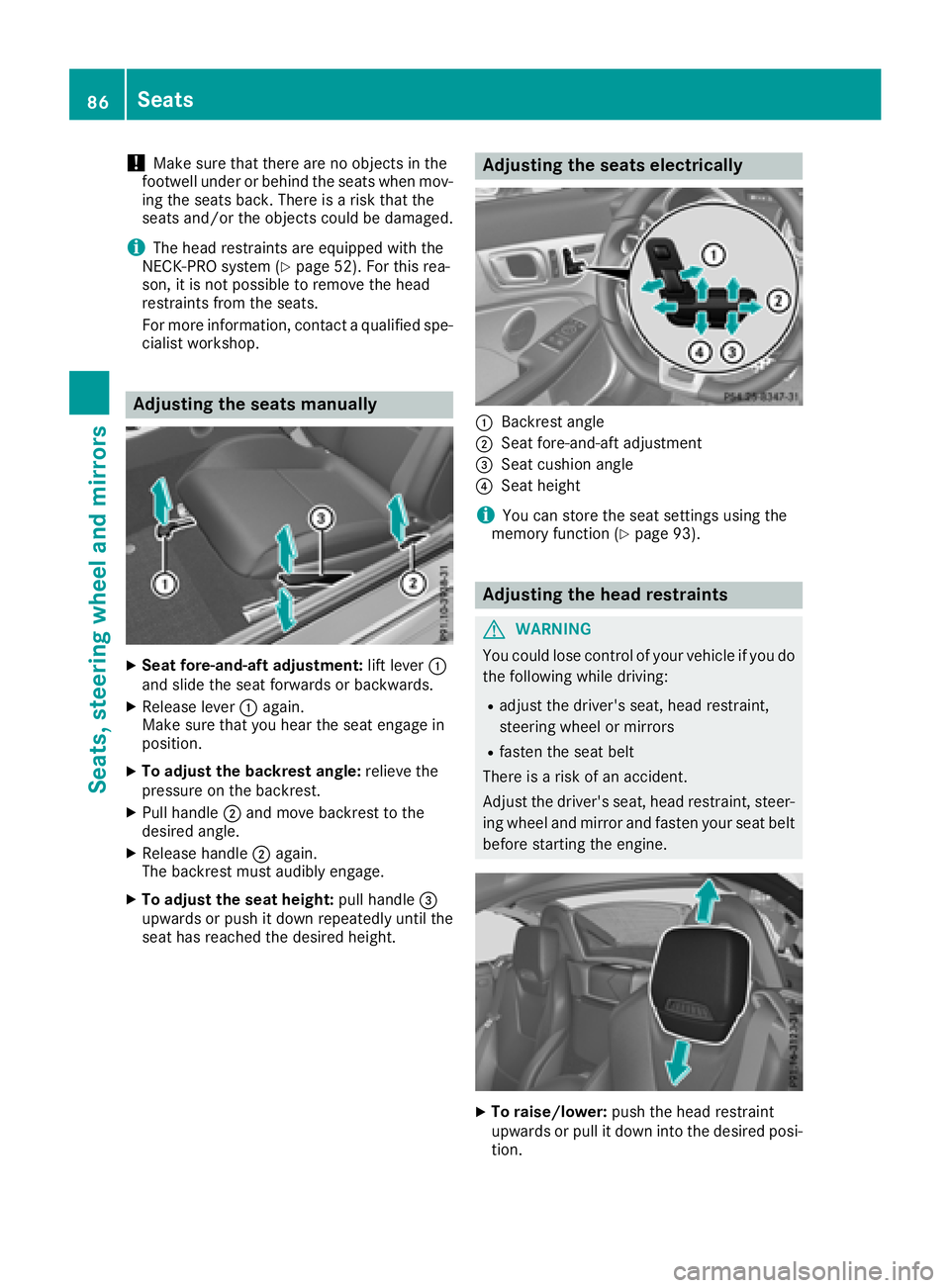
Adjusting the seats manually X
Seat fore-and-aft adjustment: lift lever �C
and slide the seat forwards or backwards. X
Release lever �C again.
Make sure that you hear the seat engage in
position. X
To adjust the backrest angle: relieve the
pressure on the backrest. X
Pull handle �D and move backrest to the
desired angle. X
Release handle �D again.
The backrest must audibly engage. X
To adjust the seat height: pull handle �
Page 157 of 298
Important safety notes The rear vie wc amera is only an aid. It is no ta
replacemen tf or your attention to your immedi-
ate surroundings. You are always responsible
for saf em aneuverin ga nd parking .M ak es ur e
that there are no persons, animals or objects in
th em aneuverin ga rea when you are maneuver-
ing or parking .
Under th ef ollowin gc ircumstances, th er ear
vie wc amera will no tf unction ,orw ill function in
al imite dm anner:R
if th et ru nk lid is openR
in heav yr ain ,s no worf ogR
at night or in ver yd ark placesR
if th ec amera is exposed to ver yb right ligh tR
if th ea rea is lit by fluorescent bulbs or LE D
lighting (the display may flicker) R
if there is as udde nc ha ng eint em perature,
e.g. when driving int oah eated garage in win -
te r R
if th ec amera len sisd irt yoro bstructed.
Observ et he note sonc leaning
( Y
page 242) R
if th er ear of your vehicl eisd amaged. In this
case, hav et he camera position and setting
checke dataq ualified specialist workshop
The field of vision and other function soft he rear
vie wc amera may be restricted due to additional
accessories on th er ear of th ev ehicl e( e.g.
license plat eh older, bicycle rack) .
On vehicles wit hh eight-adjustable chassis,
leaving th es ta ndard height can result in inac-
curacie si nt he g uide lines, depending on tech -
ni
cal conditions.
i The contras toft he display may be affecte d
by th es udde np resence of sunligh toro th er
ligh ts ources, e.g. when exiting ag arage. Pay
particular attention in this situation .
i If usabilit yiss everely restricted, e.g. due to
pixel errors ,h ave th ed isplay repaire do r
replaced.
i The rear vie wc amera is protected from rain -
drops and dust by mean sofaf lap .W hen th e
rear vie wc amera is activated, this flap opens.
The flap closes again when :R
you hav ef inishe dt he maneuverin gp rocessR
you switch off th ee ng in eR
you open th et ru nk
Observ et he note sonc leaning ( Y
page 242). Fo rt echn ical reasons, th ef lap may remain
open briefly after th er ear vie wc amera has
been deactivated.
Activating/deactivating th er ea rv iew
camera X
To activate: mak es ur et ha tt he SmartKey is
in position �H in th ei gnition lock.X
Mak es ur et ha tt he Activatio nbyRg ea r
function is selected in th em ultimedia system;
see th eD ig ital Owner' sM anual.X
Engage revers eg ear .
The rear vie wc amera flap opens. The multi-
media system shows th ea rea behind th ev ehi-
cle wit hg uide lines.
The imag ef ro mt he rear vie wc amera is avail-
able throughout th em aneuverin gp rocess.
To deactivate: th er ear vie wc amera deacti -
vates if you driv ef orwards as hort distances or
shif tt he transmission to �] .
The inner segments of th ew arning indicator are
displayed in red if there is ac om plete system
failure. The indicator lamp in th eP AR KTRONIC
butto nl ights up.
If th er ear system fails :R
th er ear segments are displayed in red when
reversing R
th er ear segments are no td isplayed when
driving forwards
Display sint he multimedi as ystemThe rear vie wc amera may sho wad istorted vie w
of obstacles, sho wt he mi ncorrectl yorn ot at all.
The rear vie wc amera does no ts ho wo bjects in
th ef ollowin gp ositions: R
ver yc lose to th er ear bumper R
under th er ear bumper R
in close range abov et he handle on th et ru nk
lid
! Objects no tatg round level may appear to
be further away than they actually are, e.g. :R
th eb umper of ap arked vehicl eR
th ed rawbar of at ra ilerR
th eb all couplin gofat ra iler to wh itchR
th er ear section of an HGV R
as lante dp os tDriving systems 155
Driving and parking Z
Page 281 of 298
Speed rating The speed rating is part of the tire identification.
It specifies the speed range for which the tire is
approved.
GVW (Gross Vehicle Weight) The gross vehicle weight includes the weight of
the vehicle including fuel, tools, the spare wheel,
accessories installed, occupants, luggage and
the drawbar noseweight, if applicable. The gross
vehicle weight must not exceed the gross vehi-
cle weight rating GVWR as specified on the vehi-
cle identification plate on the B-pillar on the
driver's side.
GVWR (Gross Vehicle Weight Rating) The GVWR is the maximum permissible gross
weight of af ully loaded vehicle (the weight of the
vehicle including all accessories, occupants,
fuel, luggage and the drawbar noseweight, if
applicable). The gross vehicle weight rating is
specified on the vehicle identification plate on
the B-pillar on the driver's side.
Maximu ml oaded vehicle weightThe maximum weight is the sum of: R
the curb weight of the vehicle R
the weight of the accessories R
the load limit R
the weight of the factory installed optional
equipment
Kilopascal (kPa) Metric unit for tire pressure. 6.9 kPa corre-
sponds to 1p si. Another unit for tire pressure is
bar. 100 kilopascals (kPa) are the equivalent of
1b ar.
Load index
In addition to the load-bearing index, the load
index may also be imprinted on the sidewal lo f
the tire. This specifies the load-bearing capacity
more precisely.
Curb weight
The weight of av ehicle with standard equipment
including the maximum capacity of fuel, oil and
coolant. It also includes the air-conditioning sys-
tem and optional equipment if these are instal-
led in the vehicle, but does not include passen-
gers or luggage. Maximu ml oad ratingThe maximum load rating is the maximum per-
missible weight in kilograms or lbs for which a
tire is approved.
Maximu mp ermissible tire pressureMaximum permissible tire pressure for one tire.
Maximu ml oad on one tireMaximum load on one tire. This is calculated by
dividing the maximum axle load of one axle by
two.
PSI (pounds per squar ei nch)As tandard unit of measure for tire pressure.
Aspect ratio Relationship between tire height and tire width
in percent.
Tire pressure This is pressure inside the tire applying an out-
ward force to each square inch of the tire's sur-
face. The tire pressure is specified in pounds per
square inch (psi), in kilopascal (kPa) or in bar.
The tire pressure should only be corrected when
the tires are cold.
Cold tire pressure The tires are cold: R
if the vehicle has been parked with the tires
out of direct sunlight for at least three hours
and R
if the vehicle has not been driven further than
1m ile (1.6 km)
Tread
The part of the tire that comes into contact with
the road.
Bead
The tire bead ensures that the tire sits securely
on the wheel. There are several steel wires in the
bead to prevent the tire from coming loose from
the wheel rim.
Sidewall
The part of the tire between the tread and the
bead.All about wheel sa nd tires 279
Wheels and tires Z
Page 284 of 298
must be positioned vertically, directly under
the jacking point of the vehicle.
! Only position the jack at the appropriate
jacking point of the vehicle. Otherwise, you
could damage the vehicle.
Observe the following when raising the vehicle: R
To rais et he vehicle, only use the vehicle-spe-
cific jack that has been tested and approved
by Mercedes-Benz. If used incorrectly, the
jack could tip over with the vehicl er aised.R
The jack is designed only to rais ea nd hold the
vehicl ef or as hort time while aw hee lisb eing
changed. It must not be used for performing
maintenance work under the vehicle. R
Avoid changing the whee lonu phill and down-
hill slopes. R
Before raising the vehicle, secure it from roll-
ing awa ybya pplying the parking brake and
inserting whee lc hocks. Do not disengage the
parking brake whil et he vehicl eisr aised.R
The jack must be placed on af irm, flat and
non-slip surface. On al oose surface, al arge,
flat, load-bearing underlay must be used .Ona
slippery surface, an on-slip underlay must be
used ,e .g. rubber mats.R
Do not use wooden blocks or similar objects
as aj ack underlay .O therwise, the jack wil ln ot
be abl etoa chieve its load-bearing capacity
due to the restricted height. R
Make sure that the distance betwee nt he
underside of the tires and the ground does not
exceed 1.2 in (3 cm). R
Never place you rh ands and feet under the
raised vehicle. R
Do not lie under the vehicle. R
Do not start the engine when the vehicl ei s
raised. R
Do not open or close ad oor or the trunk lid
when the vehicl eisr aised.R
Make sure that no persons are present in the
vehicl ew hen the vehicl eisr aised. X
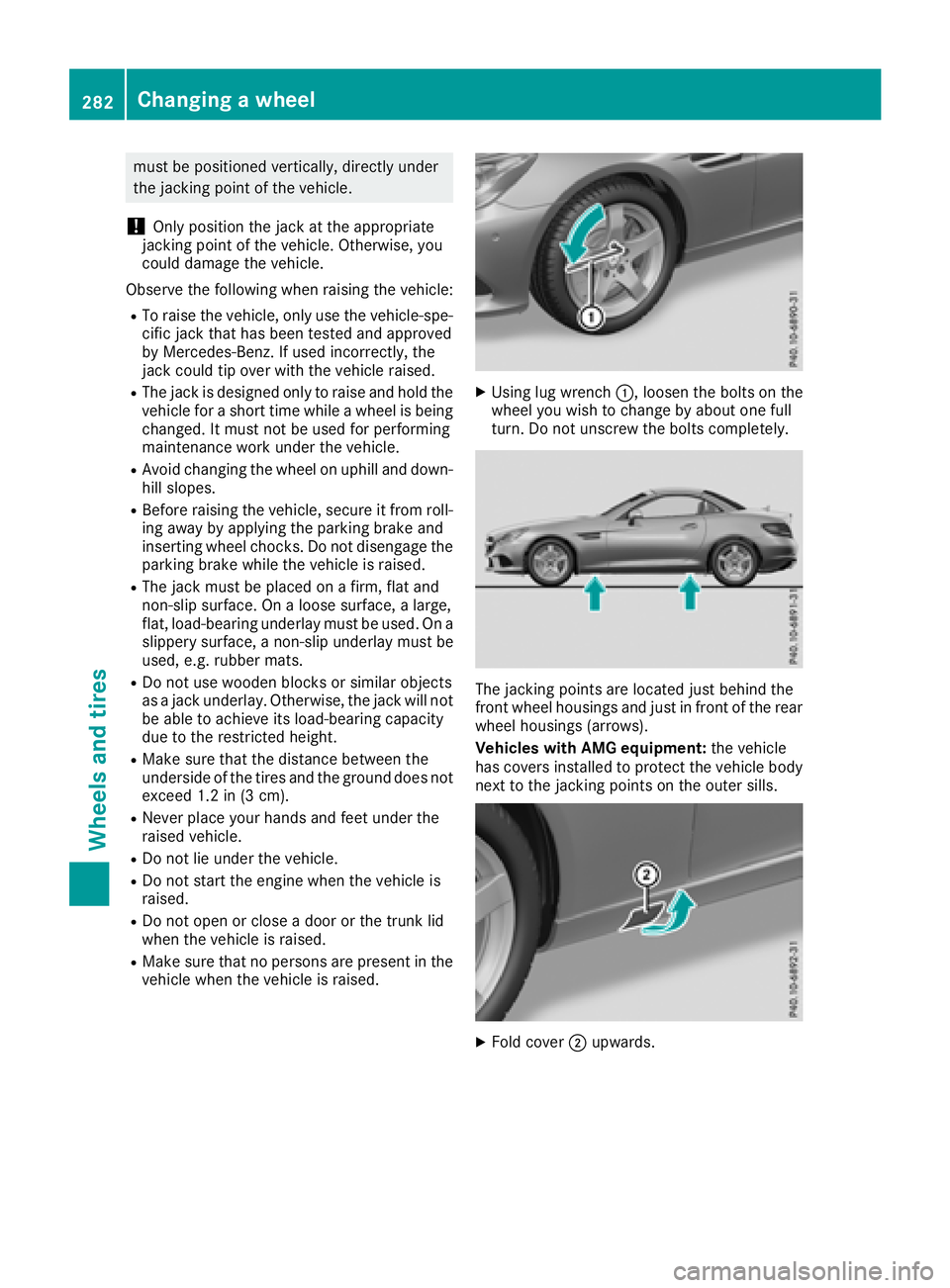
Using lug wrench �C ,l oose nt he bolts on the
whee ly ou wish to change by abou to ne full
turn. Do not unscrew the bolts completely.
The jacking points are located just behind the
front whee lh ousings and just in front of the rear
whee lh ousings (arrows).
Vehicles with AMG equipment: the vehicle
has covers installed to protect the vehicl eb ody
next to the jacking points on the outer sills.
X
Fold cover �D upwards.282
Changing aw heel
Wheel sa nd tires
Page 298 of 298
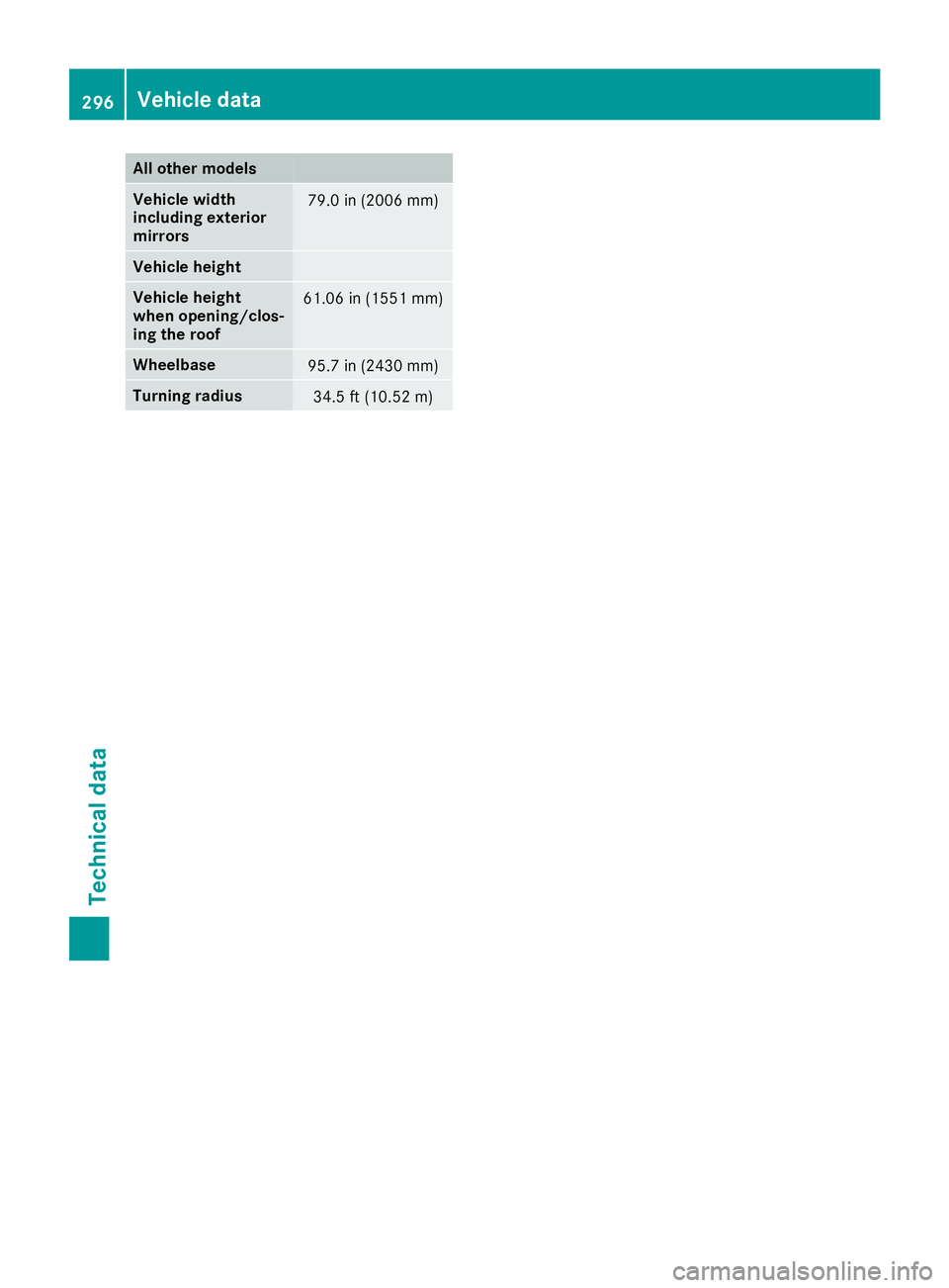
All other mod els
Vehicle width
includin ge xteri or
mir ror s 79.0 in (2006 mm)
Vehicle height
Vehicle height
when opening/clos-
ing th er oof 61.0 6in( 155 1m m)
Wh eelbase
95.7 in (2430 mm)
Tu rn ing ra dius
34.5 ft (10.52 m)296
Vehicle data
Technical data