MERCEDES-BENZ SL ROADSTER 2016 Owners Manual
Manufacturer: MERCEDES-BENZ, Model Year: 2016, Model line: SL ROADSTER, Model: MERCEDES-BENZ SL ROADSTER 2016Pages: 333, PDF Size: 11.85 MB
Page 261 of 333
R
access to the phone book of the mobile phone
(if supported by the mobile phone)
(Y page 259)
R charging a mobile phone via the USB connec-
tion (Y page 260)
i The module is not available in all vehicles,
depending on the equipment.
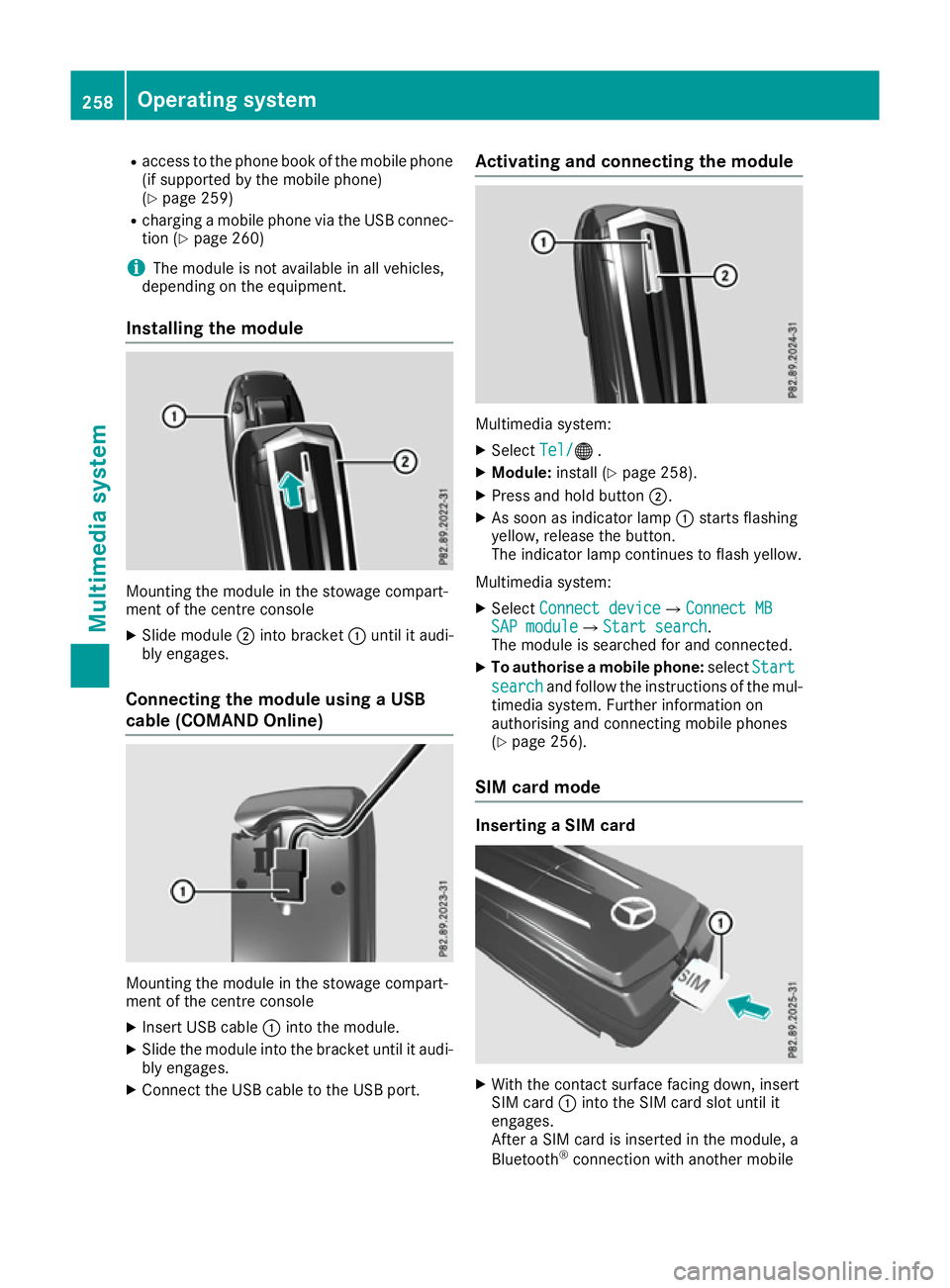
Installing the module Mounting the module in the stowage compart-
ment of the centre console
X Slide module ;into bracket :until it audi-
bly engages.
Connecting the module using a USB
cable (COMAND Online) Mounting the module in the stowage compart-
ment of the centre console
X Insert USB cable :into the module.
X Slide the module into the bracket until it audi-
bly engages.
X Connect the USB cable to the USB port. Activating and connecting the module
Multimedia system:
X Select Tel/ Tel/® .
X Module: install (Y page 258).
X Press and hold button ;.
X As soon as indicator lamp :starts flashing
yellow, release the button.
The indicator lamp continues to flash yellow.
Multimedia system: X Select Connect device Connect device QConnect MBConnect MB
SAP module
SAP module QStart searchStart search .
The module is searched for and connected.
X To authorise a mobile phone: selectStart
Start
search
search and follow the instructions of the mul-
timedia system. Further information on
authorising and connecting mobile phones
(Y page 256).
SIM card mode Inserting a SIM card
X
With the contact surface facing down, insert
SIM card :into the SIM card slot until it
engages.
After a SIM card is inserted in the module, a
Bluetooth ®
connection with another mobile 258
Operating systemMultimedia system
Page 262 of 333
phone is no longer possible. Any existing
Bluetooth
®
connection is ended upon SIM
card insertion.
Connecting the mobile phone General notes
Before using your mobile phone with the module and the multimedia system for the first time, youwill need to search for the phone and then
authorise it.
Requirements The mobile phone can be authorised and con-
nected to the module if:
R the module is installed (Y page 258) and acti-
vated in the multimedia system
(Y page 258)
R no SIM card is inserted in the module
R the mobile phone has no active Bluetooth ®
connection to another device
R the mobile phone supports the Bluetooth ®
SAP profile (SIM AccessProfile)
Depending on the type of mobile phone, differ-
ent settings must be changed on the mobile
phone (see the manufacturer's operating
instructions).
R Bluetooth ®
must be activated on the mobile
phone and must be made visible to other devi-
ces
R the Bluetooth ®
SIM Access Profile of the
mobile phone must be activated
Authorising and connecting a mobile
phone Multimedia system:
X Select Connect device Connect device QSearch forSearch for
phones
phones QSAP phoneSAP phoneQ Start
Start
search
search QMB SAP module phonesMB SAP module phones
X Select the mobile phone.
X Enter and confirm any 16-digit PIN.
X Enter and confirm the same PIN on the mobile
phone.
X Where necessary, enter the SIM card PIN into
the multimedia system and confirm.
i Please observe the messages in the mobile
phone. If necessary, you will be asked to con-
firm further profile requests. Switching between mobile phones
If you have authorised more than one mobile
phone on the module, you can switch between
the individual phones.
X Select the mobile phone under MB
MB SAP SAP mod‐
mod‐
ule phones
ule phones .
X Confirm the connection request (see the man-
ufacturer's operating instructions).
X Where necessary, enter the SIM card PIN into
the multimedia system and confirm.
Data modem mode X
Connect the mobile phone to the module
(Y page 259).
or
X Insert the SIM card into the SIM card slot on
the module (Y page 258).
X Before connecting for the first time, enable
the module for Internet access and select the
network provider in the multimedia system
(see the manufacturer's operating instruc-
tions).
Use as a data modem is automatically activa- ted.
X Activate/deactivate data roaming (see the
manufacturer's operating instructions).
For further information on data mode without
telephony with COMAND Online (see the man-
ufacturer's operating instructions).
Settings Storing/deleting the SIM card PIN
Multimedia system:
X Select Connect Connect device
deviceQMBMBSAP
SAP module
module
phones
phones
X Highlight the mobile phone.
X To select G: navigate to the right.
X Activate Oor deactivate ªStore PINStore PIN.
Transferring the phone book In order to use the phone book of the mobile
phone via the multimedia system, the phone
book must be transferred using the module.
The transfer of data may take up to ten minutes.
Transmission occurs automatically after a Blue-
tooth ®
connection is automatically established. Operating system
259Multimedia system Z
Page 263 of 333
Text messages
Requirements
The module is connected with the mobile phone
(Y page 259) or is being used in the SIM card
mode (Y page 258).
Activating/deactivating text message
downloading from the mobile phone Dial number Function
00080 Text message down-
loading is deactiva-
ted.
00081 Text message down-
loading is activated.
For further information on receiving text mes-
sages when using the telephone module (see
the manufacturer's operating instructions).
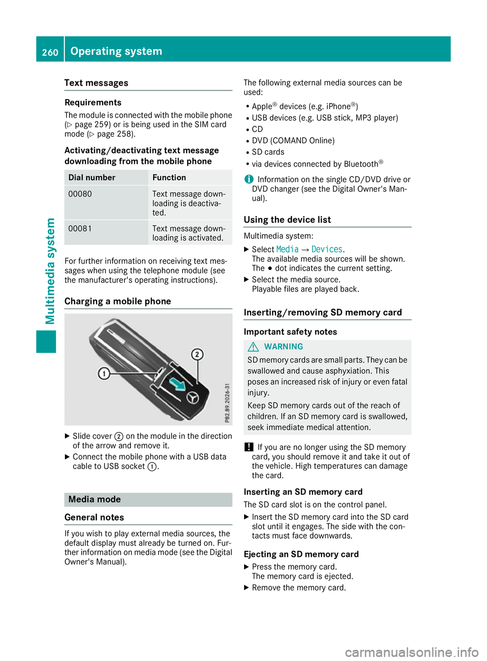
Charging a mobile phone X
Slide cover ;on the module in the direction
of the arrow and remove it.
X Connect the mobile phone with a USB data
cable to USB socket :.Media mode
General notes If you wish to play external media sources, the
default display must already be turned on. Fur-
ther information on media mode (see the Digital
Owner's Manual). The following external media sources can be
used:
R Apple ®
devices (e.g. iPhone ®
)
R USB devices (e.g. USB stick, MP3 player)
R CD
R DVD (COMAND Online)
R SD cards
R via devices connected by Bluetooth ®
i Information on the single CD/DVD drive or
DVD changer (see the Digital Owner's Man-
ual).
Using the device list Multimedia system:
X Select Media MediaQ Devices
Devices.
The available media sources will be shown.
The #dot indicates the current setting.
X Select the media source.
Playable files are played back.
Inserting/removing SD memory card Important safety notes
G
WARNING
SD memory cards are small parts. They can be swallowed and cause asphyxiation. This
poses an increased risk of injury or even fatal injury.
Keep SD memory cards out of the reach of
children. If an SD memory card is swallowed,
seek immediate medical attention.
! If you are no longer using the SD memory
card, you should remove it and take it out of
the vehicle. High temperatures can damage
the card.
Inserting an SD memory card
The SD card slot is on the control panel.
X Insert the SD memory card into the SD card
slot until it engages. The side with the con-
tacts must face downwards.
Ejecting an SD memory card X Press the memory card.
The memory card is ejected.
X Remove the memory card. 260
Operating systemMultimedia system
Page 264 of 333
Connecting USB devices
There are two USB ports in the stowage space
under the armrest.
X Connect the USB device to the USB port.
X Select the media source (Y page 260). Operating system
261Multimedia system Z
Page 265 of 333
Stowage areas
Stowage compartments
Important safety notes G
WARNING
If objects in the passenger compartment are
stowed incorrectly, they can slide or be
thrown around and hit vehicle occupants. In
addition, cupholders, open stowage spaces
and mobile phone brackets cannot always
retain all objects they contain. There is a risk of injury, particularly in the event of sudden
braking or a sudden change in direction.
R Always stow objects so that they cannot be
thrown around in such situations.
R Always make sure that objects do not pro-
trude from stowage spaces, parcel nets or
stowage nets.
R Close the lockable stowage spaces before
starting a journey.
R Always stow and secure heavy, hard, poin-
ted, sharp-edged, fragile or bulky objects in
the boot.
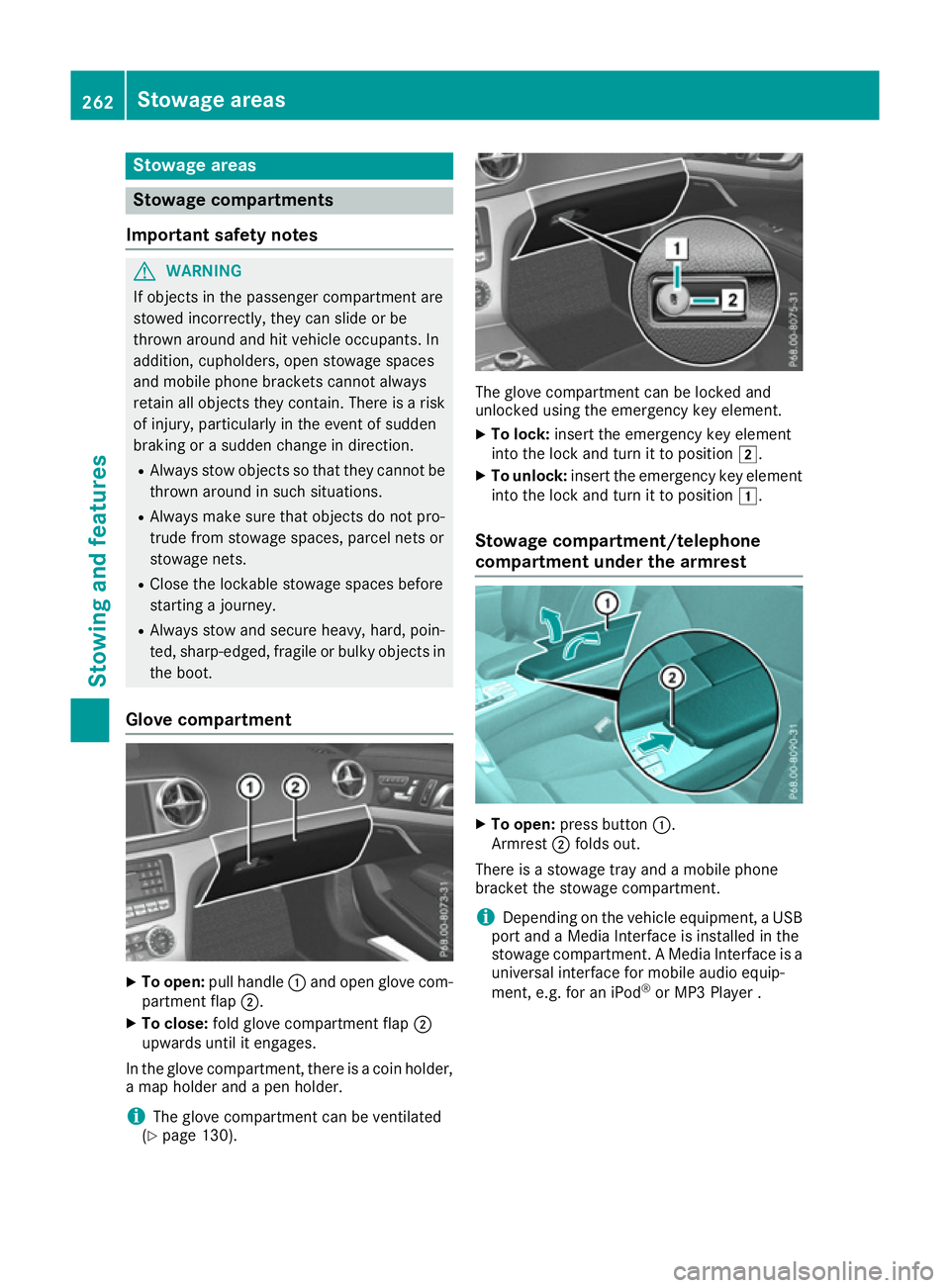
Glove compartment X
To open: pull handle :and open glove com-
partment flap ;.
X To close: fold glove compartment flap ;
upwards until it engages.
In the glove compartment, there is a coin holder, a map holder and a pen holder.
i The glove compartment can be ventilated
(Y page 130). The glove compartment can be locked and
unlocked using the emergency key element.
X To lock: insert the emergency key element
into the lock and turn it to position 2.
X To unlock: insert the emergency key element
into the lock and turn it to position 1.
Stowage compartment/telephone
compartment under the armrest X
To open: press button :.
Armrest ;folds out.
There is a stowage tray and a mobile phone
bracket the stowage compartment.
i Depending on the vehicle equipment, a USB
port and a Media Interface is installed in the
stowage compartment. A Media Interface is a universal interface for mobile audio equip-
ment, e.g. for an iPod ®
or MP3 Player . 262
Stowage areasStowing and features
Page 266 of 333
Spectacles compartment
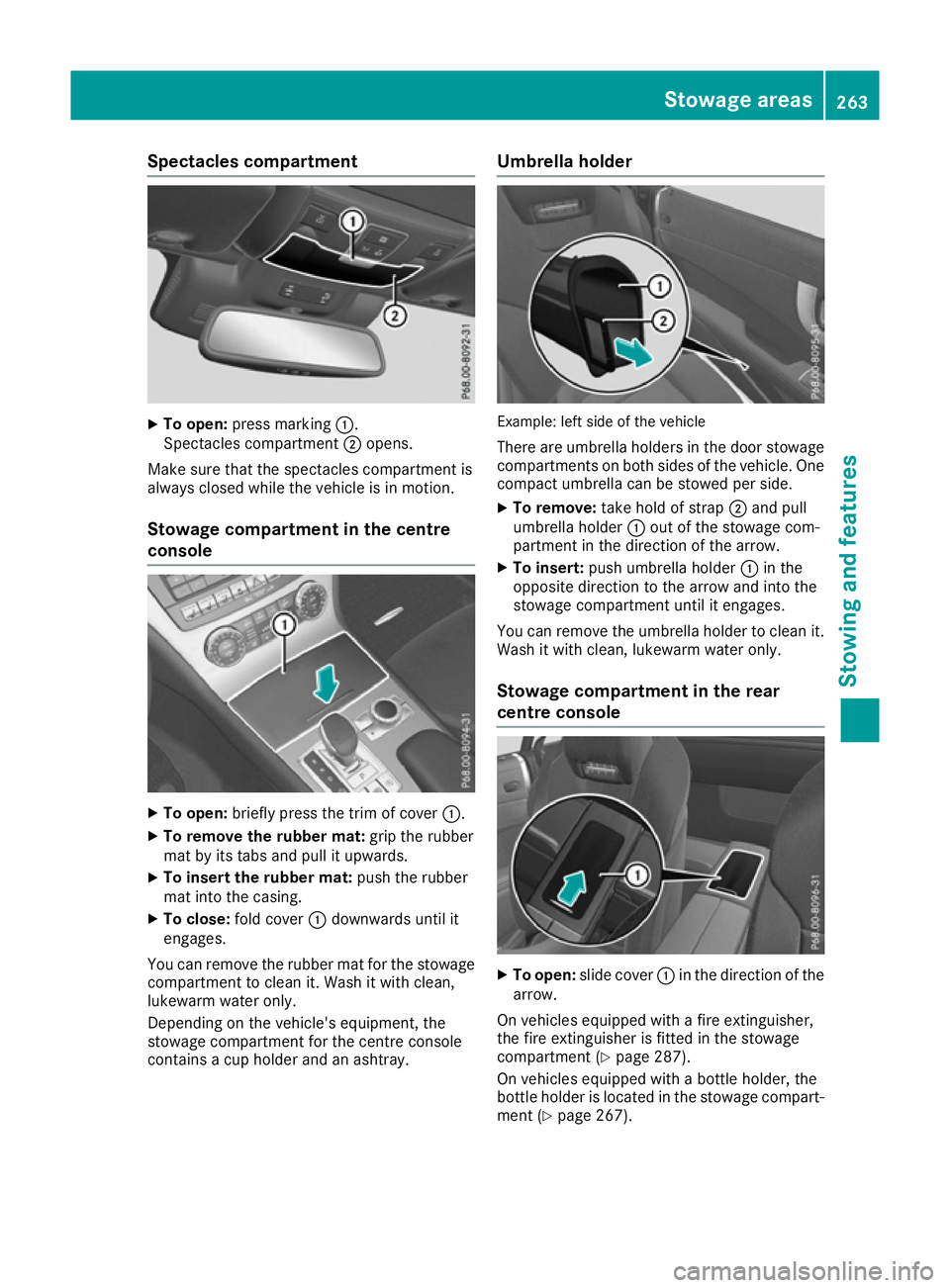
X
To open: press marking :.
Spectacles compartment ;opens.
Make sure that the spectacles compartment is
always closed while the vehicle is in motion.
Stowage compartment in the centre
console X
To open: briefly press the trim of cover :.
X To remove the rubber mat: grip the rubber
mat by its tabs and pull it upwards.
X To insert the rubber mat: push the rubber
mat into the casing.
X To close: fold cover :downwards until it
engages.
You can remove the rubber mat for the stowage
compartment to clean it. Wash it with clean,
lukewarm water only.
Depending on the vehicle's equipment, the
stowage compartment for the centre console
contains a cup holder and an ashtray. Umbrella holder
Example: left side of the vehicle
There are umbrella holders in the door stowage
compartments on both sides of the vehicle. One compact umbrella can be stowed per side.
X To remove: take hold of strap ;and pull
umbrella holder :out of the stowage com-
partment in the direction of the arrow.
X To insert: push umbrella holder :in the
opposite direction to the arrow and into the
stowage compartment until it engages.
You can remove the umbrella holder to clean it. Wash it with clean, lukewarm water only.
Stowage compartment in the rear
centre console X
To open: slide cover :in the direction of the
arrow.
On vehicles equipped with a fire extinguisher,
the fire extinguisher is fitted in the stowage
compartment (Y page 287).
On vehicles equipped with a bottle holder, the
bottle holder is located in the stowage compart- ment (Y page 267). Stowage areas
263Stowing and features Z
Page 267 of 333
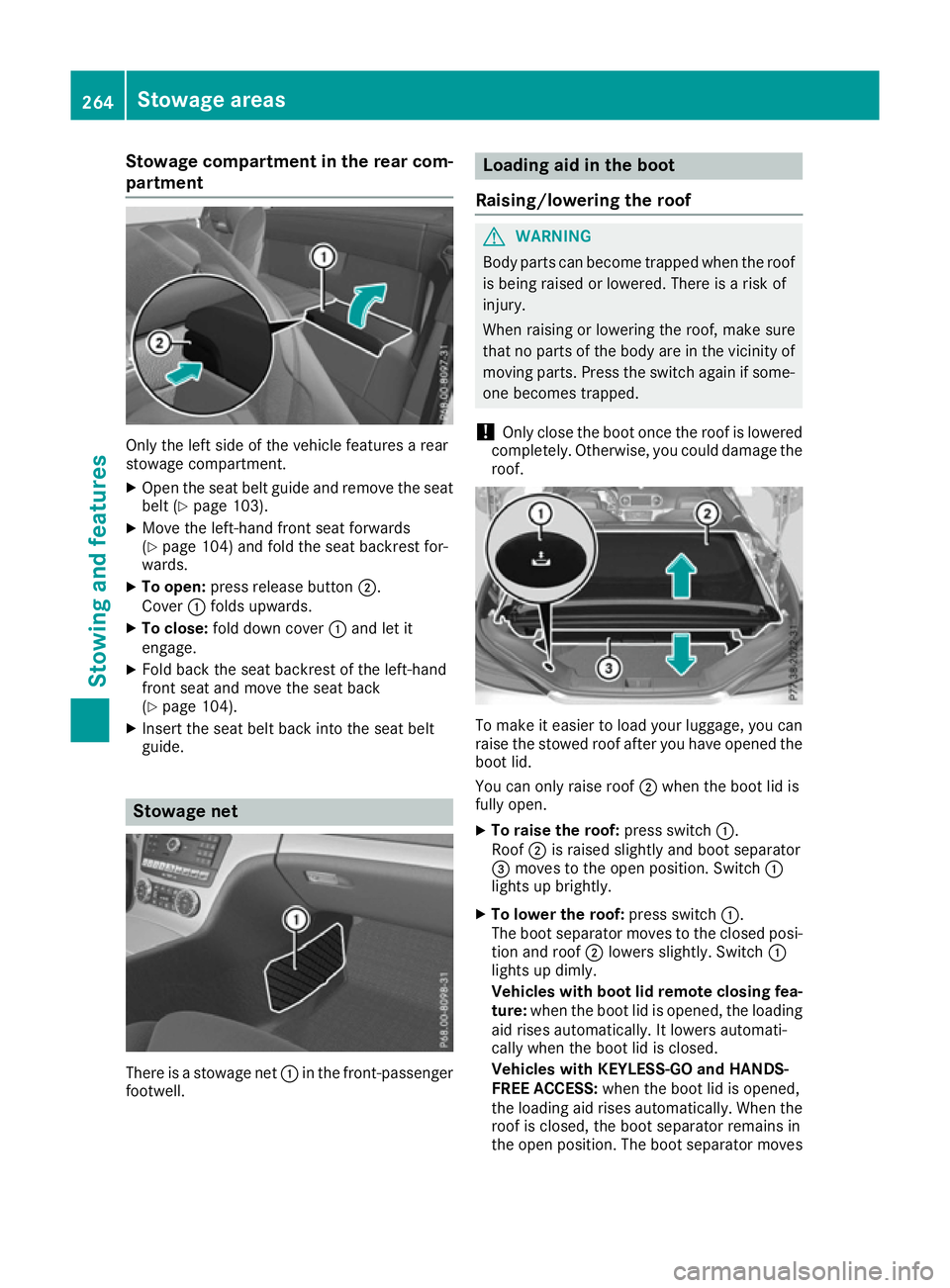
Stowage compartment in the rear com-
partment Only the left side of the vehicle features a rear
stowage compartment.
X Open the seat belt guide and remove the seat
belt (Y page 103).
X Move the left-hand front seat forwards
(Y page 104) and fold the seat backrest for-
wards.
X To open: press release button ;.
Cover :folds upwards.
X To close: fold down cover :and let it
engage.
X Fold back the seat backrest of the left-hand
front seat and move the seat back
(Y page 104).
X Insert the seat belt back into the seat belt
guide. Stowage net
There is a stowage net
:in the front-passenger
footwell. Loading aid in the boot
Raising/lowering the roof G
WARNING
Body parts can become trapped when the roof is being raised or lowered. There is a risk of
injury.
When raising or lowering the roof, make sure
that no parts of the body are in the vicinity of moving parts. Press the switch again if some-
one becomes trapped.
! Only close the boot once the roof is lowered
completely. Otherwise, you could damage the roof. To make it easier to load your luggage, you can
raise the stowed roof after you have opened the boot lid.
You can only raise roof ;when the boot lid is
fully open.
X To raise the roof: press switch:.
Roof ;is raised slightly and boot separator
= moves to the open position. Switch :
lights up brightly.
X To lower the roof: press switch:.
The boot separator moves to the closed posi- tion and roof ;lowers slightly. Switch :
lights up dimly.
Vehicles with boot lid remote closing fea-
ture: when the boot lid is opened, the loading
aid rises automatically. It lowers automati-
cally when the boot lid is closed.
Vehicles with KEYLESS-GO and HANDS-
FREE ACCESS: when the boot lid is opened,
the loading aid rises automatically. When the
roof is closed, the boot separator remains in
the open position. The boot separator moves 264
Stowage areasStowing and features
Page 268 of 333
to the closed position automatically when the
roof is lowered. Sto
wage areas
265Stowing and features Z
Page 269 of 333
Problems with the loading aid
Problem
Possible causes/consequences and
M
MSolutions It is no longer possible to
lower the stowed roof in
the boot using the load-
ing aid. You cannot close the boot any more.
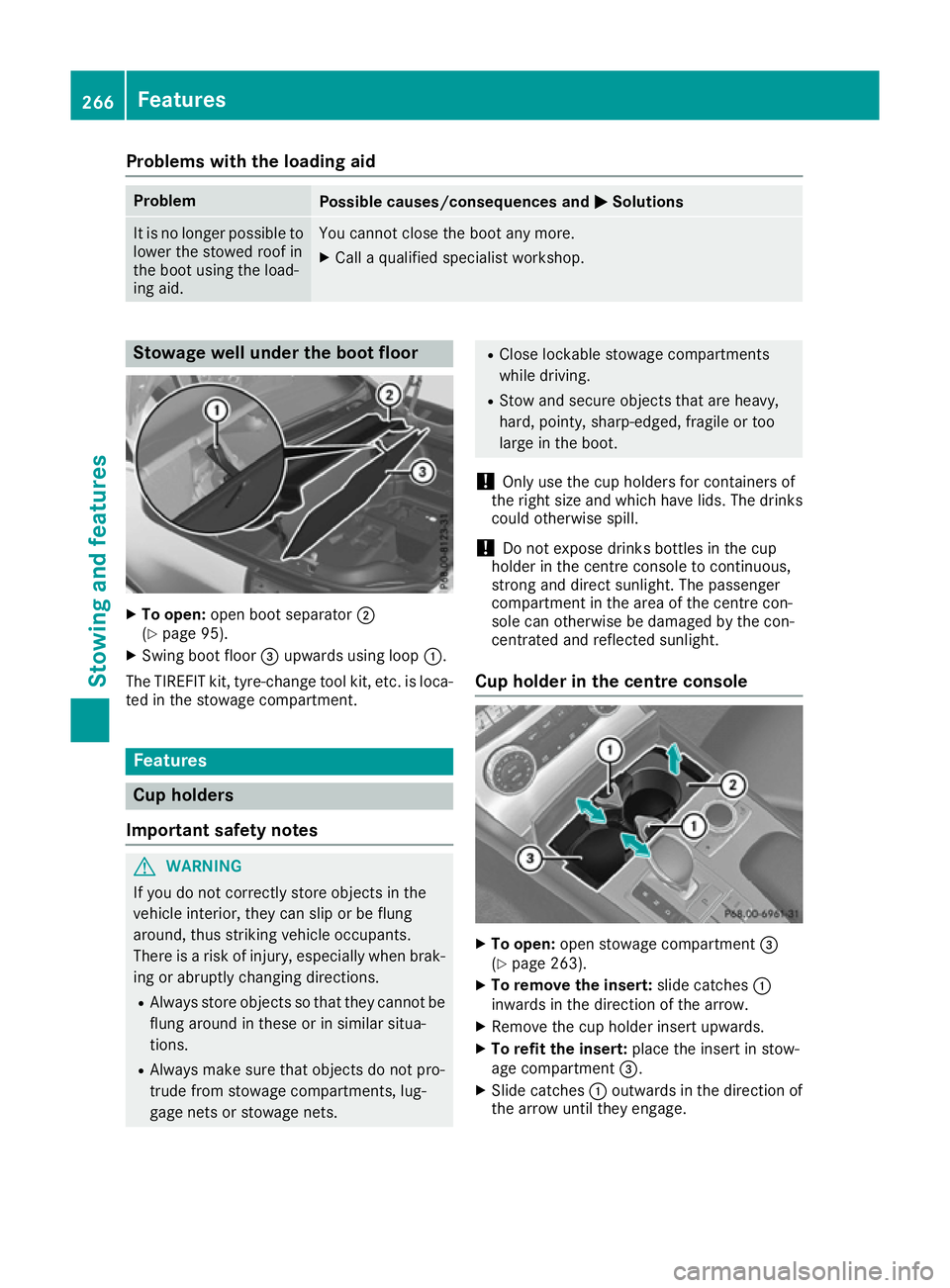
X Call a qualified specialist workshop. Stowage well under the boot floor
X
To open: open boot separator ;
(Y page 95).
X Swing boot floor =upwards using loop :.
The TIREFIT kit, tyre-change tool kit, etc. is loca-
ted in the stowage compartment. Features
Cup holders
Important safety notes G
WARNING
If you do not correctly store objects in the
vehicle interior, they can slip or be flung
around, thus striking vehicle occupants.
There is a risk of injury, especially when brak- ing or abruptly changing directions.
R Always store objects so that they cannot be
flung around in these or in similar situa-
tions.
R Always make sure that objects do not pro-
trude from stowage compartments, lug-
gage nets or stowage nets. R
Close lockable stowage compartments
while driving.
R Stow and secure objects that are heavy,
hard, pointy, sharp-edged, fragile or too
large in the boot.
! Only use the cup holders for containers of
the right size and which have lids. The drinks could otherwise spill.
! Do not expose drinks bottles in the cup
holder in the centre console to continuous,
strong and direct sunlight. The passenger
compartment in the area of the centre con-
sole can otherwise be damaged by the con-
centrated and reflected sunlight.
Cup holder in the centre console X
To open: open stowage compartment =
(Y page 263).
X To remove the insert: slide catches:
inwards in the direction of the arrow.
X Remove the cup holder insert upwards.
X To refit the insert: place the insert in stow-
age compartment =.
X Slide catches :outwards in the direction of
the arrow until they engage. 266
FeaturesStowing and features
Page 270 of 333
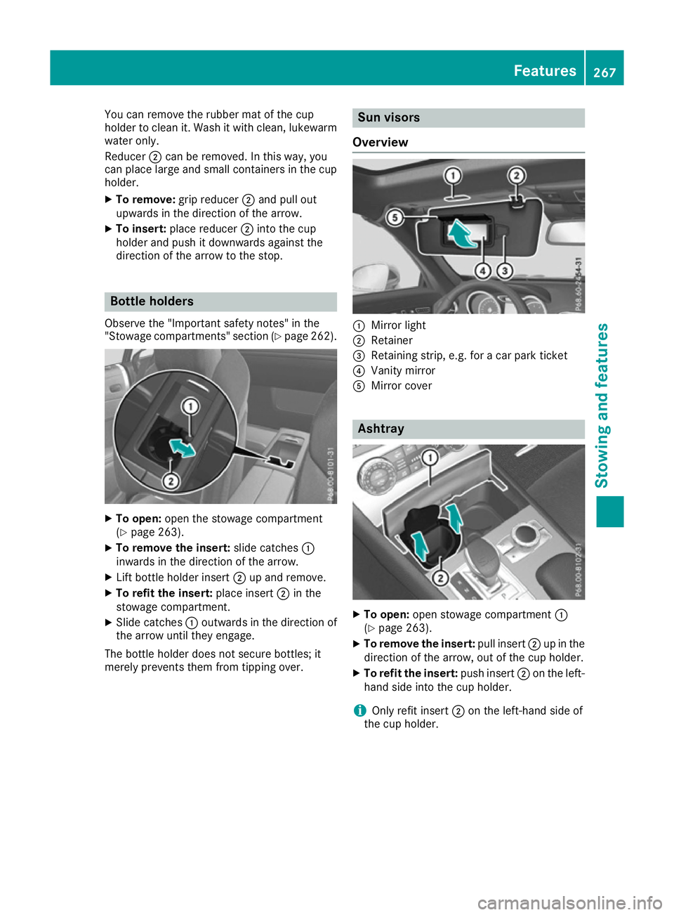
You can remove the rubber mat of the cup
holder to clean it. Wash it with clean, lukewarm water only.
Reducer ;can be removed. In this way, you
can place large and small containers in the cup
holder.
X To remove: grip reducer ;and pull out
upwards in the direction of the arrow.
X To insert: place reducer ;into the cup
holder and push it downwards against the
direction of the arrow to the stop. Bottle holders
Observe the "Important safety notes" in the
"Stowage compartments" section (Y page 262).X
To open: open the stowage compartment
(Y page 263).
X To remove the insert: slide catches:
inwards in the direction of the arrow.
X Lift bottle holder insert ;up and remove.
X To refit the insert: place insert;in the
stowage compartment.
X Slide catches :outwards in the direction of
the arrow until they engage.
The bottle holder does not secure bottles; it
merely prevents them from tipping over. Sun visors
Overview :
Mirror light
; Retainer
= Retaining strip, e.g. for a car park ticket
? Vanity mirror
A Mirror cover Ashtray
X
To open: open stowage compartment :
(Y page 263).
X To remove the insert: pull insert;up in the
direction of the arrow, out of the cup holder.
X To refit the insert: push insert;on the left-
hand side into the cup holder.
i Only refit insert
;on the left-hand side of
the cup holder. Features
267Stowing and features Z