service indicator MERCEDES-BENZ SL ROADSTER 2018 Owner's Manual
[x] Cancel search | Manufacturer: MERCEDES-BENZ, Model Year: 2018, Model line: SL ROADSTER, Model: MERCEDES-BENZ SL ROADSTER 2018Pages: 322, PDF Size: 5.43 MB
Page 4 of 322
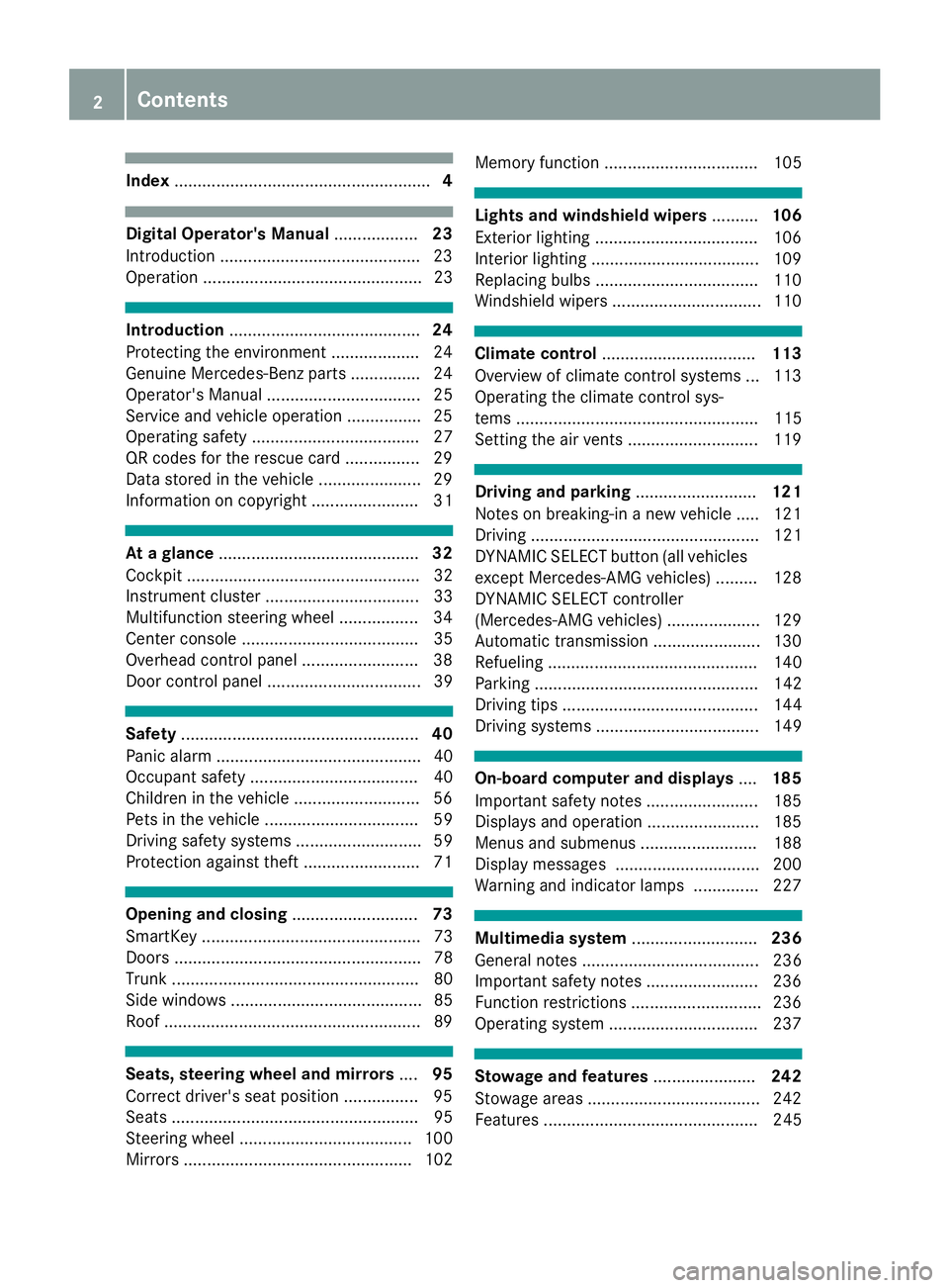
Index....................................................... 4
Digital Operator's Manual..................23
Introduction .......................................... .23
Operation ............................................... 23
Introduction ......................................... 24
Protecting the environment ...................2 4
Genuine Mercedes-Benz parts .............. .24
Operator's Manual ................................. 25
Service and vehicle operation ................2 5
Operating safety .................................... 27
QR codes for the rescue card ................2 9
Data stored in the vehicle ...................... 29
Information on copyright ....................... 31
At a glance ........................................... 32
Cockpit .................................................. 32
Instrument cluster ................................. 33
Multifunction steering wheel ................. 34
Center console ...................................... 35
Overhead control panel .........................3 8
Door control panel ................................. 39
Safety ................................................... 40
Panic alarm ............................................ 40
Occupant safety .................................... 40
Children in the vehicle ........................... 56
Pets in the vehicle ................................. 59
Driving safety systems ........................... 59
Protection against theft .........................7 1
Opening and closing...........................73
SmartKey ............................................... 73
Doors ..................................................... 78
Trunk ..................................................... 80
Side windows ......................................... 85
Roof .......................................................8 9
Seats, steering wheel and mirrors....95
Correct driver's seat position ................9 5
Seats ..................................................... 95
Steering wheel ..................................... 100
Mirrors ................................................. 102 Memory function ................................. 105
Lights and windshield wipers
..........106
Exterior lighting ................................... 106
Interior lighting .................................... 109
Replacing bulbs ................................... 110
Windshield wipers ................................ 110
Climate control ................................. 113
Overview of climate control systems ... 113
Operating the climate control sys-
tems .................................................... 115
Setting the air vents ............................ 119
Driving and parking ..........................121
Notes on breaking-in a new vehicle ..... 121
Driving ................................................. 121
DYNAMIC SELECT button (all vehicles
except Mercedes-AMG vehicles) ......... 128
DYNAMIC SELECT controller
(Mercedes-AMG vehicles) .................... 129
Automatic transmission ....................... 130
Refueling ............................................. 140
Parking ................................................ 142
Driving tips .......................................... 144
Driving systems ................................... 149
On-board computer and displays ....185
Important safety notes ........................ 185
Displays and operation ........................ 185
Menus and submenus ......................... 188
Display messages ............................... 200
Warning and indicator lamps .............. 227
Multimedia system ...........................236
General notes ...................................... 236
Important safety notes ........................ 236
Function restrictions ............................ 236
Operating system ................................ 237
Stowage and features ......................242
Stowage areas ..................................... 242
Features .............................................. 245
2Contents
Page 7 of 322
Head bag ......................................... 47
Important safety notes .................... 45
Introduction .....................................45
Knee bag .......................................... 46
Occupant Classification System
(OCS) ............................................... 47
PASSENGER AIR BAG indicator
lamps ............................................... 41
Side impact air bag .......................... 46
AIR FLOW ........................................... 116
Air vents
Glove box ....................................... 120
Important safety notes .................. 119
Setting ........................................... 119
Setting the blower output of the
AIRSCARF vents .............................1 20
Setting the center air vents ........... 120
Setting the side air vents ...............1 20
Switching AIRSCARF on/off .......... 100
Air-conditioning system
see Climate control
AIRSCARF
Switching on/off ........................... 100
AIRSCARF vents
Setting the blower output .............. 120
Alarm
ATA (Anti-Theft Alarm system) ......... 72
Switching off (ATA) .......................... 72
Switching the function on/off
(ATA) ................................................ 72
Alarm system
see ATA (Anti-Theft Alarm system)
Ambient lighting
Setting the brightness (on-board
computer) ...................................... 195
Setting the color (on-board com-
puter) ............................................. 195
AMG menu (on-board computer) ..... 197
Anti-lock braking system
see ABS (Anti-lock Braking System)
Anti-skid chains
see Snow chains
Anti-theft alarm system
see ATA (Anti-Theft Alarm system)
Ashtray ............................................... 247
Assistance display (on-board com-
puter) ..................................................1 93Assistance menu (on-board com-
puter)
..................................................1 92
ASSYST PLUS
Displaying a service message ........2
62
Hi
ding a service message .............. 262
Resetting the service interval dis-
play ................................................ 262
Service message ............................ 262
Special service requirements ......... 262
ATA (Anti-Theft Alarm system)
Activating/deactivating ................... 72
Function ...........................................7 2
Switching off the alarm .................... 72
ATTENTION ASSIST
Activating/deactivating ................. 193
Display message ............................ 216
Function/notes ............................. 177
Audio menu (on-board computer) .... 190
Audio system
see Digital Operator's Manual
Authorized Mercedes-Benz Center
see Qualified specialist workshop
Authorized workshop
see Qualified specialist workshop
AUTO lights
Display message ............................ 212
see Lights
Automatic car wash (care) ............... 263
Automatic engine start (ECO start/
stop function) .................................... 126
Automatic engine switch-off (ECO
start/stop function) .......................... 125
Automatic headlamp mode .............. 106
Automatic transmission
Accelerator pedal position ............. 133
Changing gear ............................... 133
Display message ............................ 222
Drive program ................................ 134
Drive program display .................... 131
Driving tips .................................... 133
DYNAMIC SELECT button (all vehi-
cles except Mercedes-AMG vehi-
cles) ............................................... 128
DYNAMIC SELECT controller
(Mercedes-AMG vehicles) .............. 129
Emergency running mode .............. 139
Engaging drive position .................. 132
Index5
Page 16 of 322
MP3Operation ....................................... 191
see also Digital Operator's Man-
ual .................................................. 236
Multifunction display
Function/notes ............................. 187
Permanent display ......................... 194
Multifunction steering wheel
Operating the on-board computer .. 186
Overview .......................................... 34
Multimedia system
Switching on and off ...................... 237
Music files
see also Digital Operator's Man-
ual .................................................. 236
N
NavigationEntering a destination .................... 238
Menu (on-board computer) ............ 189
see also Digital Operator's Man-
ual .................................................. 236
Navigation menu
Important safety notes .................. 189
NECK-PRO head restraints
Important safety notes .................... 55
Operation .........................................5 5
Resettin gtriggered .......................... 55
Notes on breaking-in anew vehi-
cle ...................................................... .121
O
Occupant Classification System
(OCS)
Conditions ....................................... 48
Faults ............................................... 51
Operation ......................................... 48
System self-test ............................... 50
Occupant safety
Air bags ...........................................4 5
Automatic measures after an acci-
dent ................................................. 56
Belt warning .....................................4 4
Childr eninthe vehicle .................... .56
Important safety notes .................... 40
Introduction to the restraint sys-
tem .................................................. 40 Occupant Classification System
(OCS) ............................................... 47
PASSENGER AIR BAG indicator
lamps ............................................... 41
Pets in the vehicle ........................... 59
PRE-SAFE
®(anticipatory occu-
pant protection) ............................... 55
PRE-SAFE
®PLUS (anticipatory
occupant protection PLUS) .............. 56
Restraint system warning lamp ........ 40
Seat belt .......................................... 41
OCS
Conditions ....................................... 48
Faults ............................................... 51
Operation .........................................4 8
System self-test ............................... 50
Odometer ........................................... 188
Oil
see Engine oil
On-board computer
AMG menu ..................................... 197
Assistance menu ........................... 192
Audio menu ................................... 190
Convenience submenu .................. 196
Display messages .......................... 200
Displaying a service message ........ 262
Factory settings submenu ............. 197
Important safety notes .................. 185
Instrument cluster submenu .......... 194
Lighting submenu .......................... 195
Menu overview .............................. 188
Message memory .......................... 200
Navigation menu ............................ 189
Operation ....................................... 186
RACET
IMER ................................... 198
Service menu ................................. 194
Settings menu ............................... 194
Standard display ............................ 188
Telephone menu ............................ 191
Trip menu ...................................... 188
Vehicle submenu ........................... 196
Video DVD operation ..................... 191
Operating safety
Declaration of conformity ................ 27
Important safety notes .................... 27
Operating system
see On-board computer
14Index
Page 146 of 322
If the seat belt tongue is not engaged in the seat
belt buckle, the following conditions must be
fulfilled:
Rthe driver's door is closed
Ryou move the transmission out of positionj
or you have previously driven at a speed
above 2 mph (3 km/h)
Rif the transmission is in position k, the trunk
lid must be closed
When the electric parking brake is released,
the ! indicator lamp goes out in the instru-
ment cluster.
Emergency braking
The vehicle can also be braked during an emer- gency by using the electric parking brake.
XWhile driving, push handle :of the electric
parking brake.
The vehicle is braked for as long as the handle
of the electric parking brake is pressed. The
longer the electric parking brake handle is
depressed, the greater the braking force.
During braking:
Ra warning tone sounds
Rthe Release Parking Brakemessage
appears
Rthe red F(USA only) or !(Canada
only) indicator lamp in the instrument cluster flashes
When the vehicle has been braked to a stand-
still, the electric parking brake is engaged.
Parking the vehicle for a long period
If you leave the vehicle parked for longer than
four weeks, the battery may be damaged by
exhaustive discharging.
If you leave the vehicle parked for longer than six
weeks, the vehicle may suffer damage as a
result of lack of use.
XVisit a qualified specialist workshop and seek
advice.
iYou can obtain information about trickle
chargers from a qualified specialist work-
shop.
Driving tips
General notes
Important safety notes
GWARNING
If you switch off the ignition while driving,
safety-relevant functions are only available
with limitations, or not at all. This could affect, for example, the power steering and the brake
boosting effect. You will require considerably
more effort to steer and brake. There is a risk
of an accident.
Do not switch off the ignition while driving.
GWARNING
If you operate mobile communication equip-
ment when driving, you may be distracted
from the traffic situation. You could also lose
control of the vehicle. There is a risk of an
accident.
Only operate this equipment when the vehicle
is stationary.
Observe the legal requirements for the country
in which you are driving. Some jurisdictions pro-
hibit the driver from using a mobile phone while driving a vehicle.
If you make a call while driving, always use
hands-free mode. Only operate the telephone
when the traffic situation permits. If you are
unsure, pull over to a safe location and stop
before operating the telephone.
Bear in mind that at a speed of only 30 mph
(approximately 50 km/h), the vehicle covers a
distance of 44 ft (approximately 14 m)per sec-
ond.
Drive sensibly – save fuel
Observe the following tips to save fuel:
RThe tires should always be inflated to the rec-
ommended tire pressure.
RRemove unnecessary loads.
RWarm up the engine at low engine speeds.
RAvoid frequent acceleration or braking.
RObserve the service intervals in the Mainte-
nance Booklet or in the service interval dis-
144Driving tips
Driving and parking
Page 181 of 322
this is that ATTENTION ASSIST still detects typ-ical indicators of fatigue or increasing lapses in
concentration.
Vehicles with COMAND: if a warning is issued
in the multifunction display, a service station
search is performed in COMAND. You can select
a service station and navigation to this service
station will then begin. This function can be acti- vated and deactivated in COMAND.
Active Driving Assistance package
General notes
The Active Driving Assistance package consists
of Distance Pilot DISTRONIC (Ypage 151),
Steering Pilot and Stop&Go Pilot, Active Blind
Spot Assist (
Ypage 179 )and Active Lane Keep-
ing Assist (Ypage 181).
Active Blind Spot Assist
General notes
Active Blind Spot Assist monitors the areas on
either side of the vehicle that are not directly
visible to the driver with two lateral, rear-facing
radar sensors. A warning lamp lights up in the
exterior mirrors and draws your attention to
vehicles detected in the monitored area. If you
then switch on the corresponding turn signal to
change lane, you will also receive an optical and
audible warning. If a risk of lateral collision is
detected, corrective braking may help you avoid
a collision. Before a course-correcting brake
application, Active Blind Spot Assist evaluates
the space in the direction of travel and at the
sides of the vehicle. For this, Active Blind Spot
Assist uses the forward-facing radar sensors.
Active Blind Spot Assist supports you from a
speed of approximately 20 mph (30 km/h).
Important safety notes
Active Blind Spot Assist is only an aid and is not
a substitute for attentive driving.
GWARNING
Active Blind Spot Assist does not react to:
Rvehicles overtaken too closely on the side,
placing them in the blind spot area
Rvehicles which approach with a large speed
differential and overtake your vehicle
As a result, Active Blind Spot Assist may nei-
ther give warnings nor intervene in such sit-
uations. There is a risk of an accident.
Always observe the traffic conditions care-
fully, and maintain a safe lateral distance.
iUSA only: This device has been approved by
the FCC as a "Vehicular Radar System". The
radar sensor is intended for use in an auto-
motive radar system only. Removal, tamper-
ing, or altering of the device will void any war-
ranties, and is not permitted by the FCC. Do
not tamper with, alter, or use in any non-
approved way.
Any unauthorized modification to this device
could void the user's authority to operate the
equipment.
iCanada only: This device complies with
RSS-210 of Industry Canada. Operation is
subject to the following two conditions:
1. This device may not cause interference,
and
2. This device must accept any interference
received, including interference that may
cause undesired operation of the device.
Removal, tampering, or altering of the device
will void any warranties, and is not permitted. Do not tamper with, alter, or use in any non-
approved way.
Any unauthorized modification to this device
could void the user's authority to operate the
equipment.
Radar sensors
The radar sensors for Active Blind Spot Assist
are integrated in the rear bumper and in the
radiator trim. Make sure that the bumpers and
radiator trim are free from dirt, ice and slush.
The rear sensors must not be covered, for exam-
ple by cycle racks or overhanging cargo. Fol-
lowing a severe impact or in the event of damage
to the bumpers, have the function of the radar
sensors checked at a qualified specialist work-
shop. Active Blind Spot Assist may otherwise no
longer work properly.
Monitoring area
GWARNING
Active Blind Spot Assist does not detect all
traffic situations and road users. There is a
risk of an accident.
Driving systems179
Driving an d parking
Z
Page 250 of 322
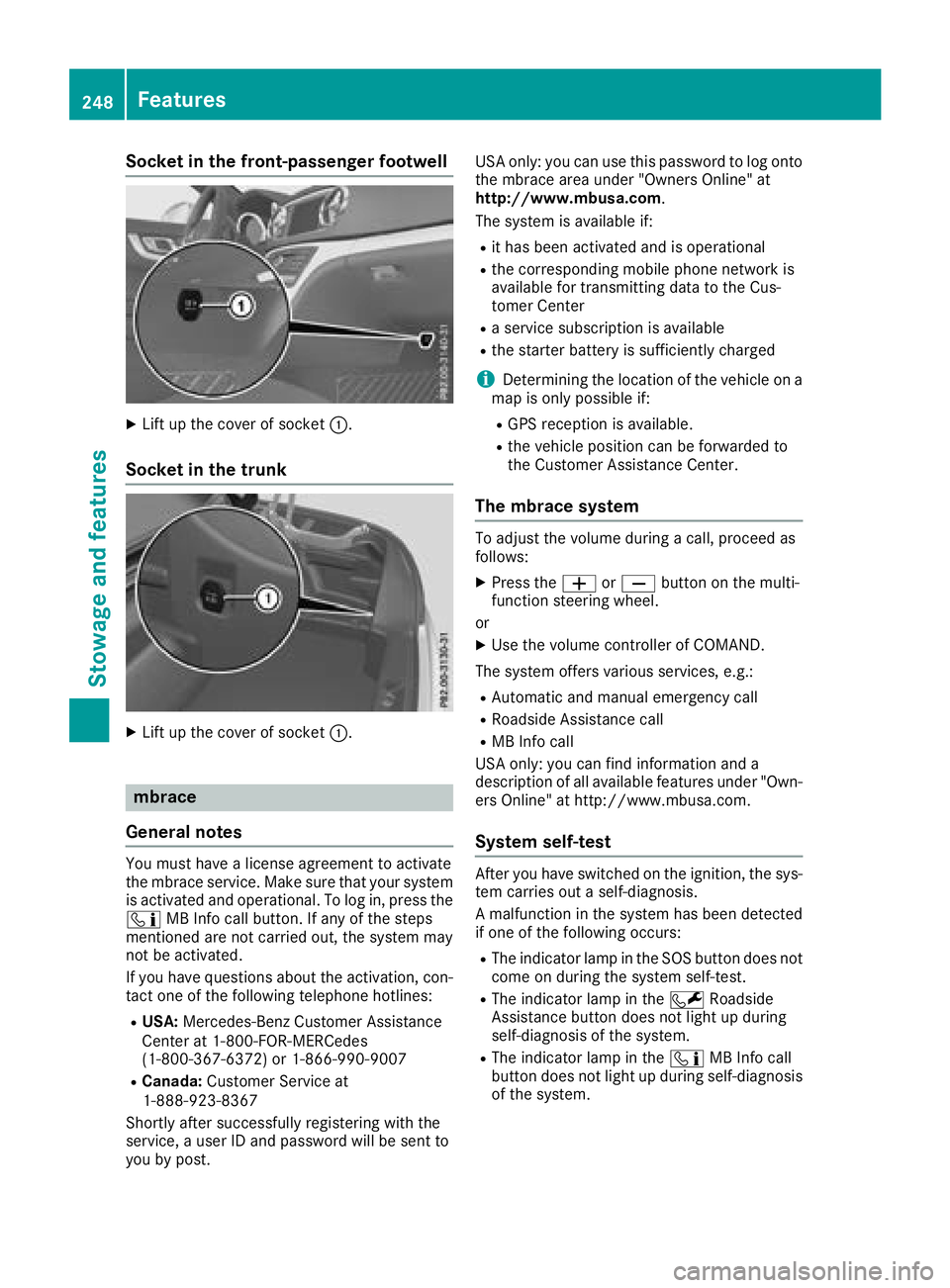
Socket in the front-passenger footwell
XLift up the cover of socket:.
Socket in the trunk
XLift up the cover of socket :.
mbrace
General notes
You must have a license agreement to activate
the mbrace service. Make sure that your system
is activated and operational. To log in, press the
ï MB Info call button. If any of the steps
mentioned are not carried out, the system may
not be activated.
If you have questions about the activation, con-
tact one of the following telephone hotlines:
RUSA: Mercedes-Benz Customer Assistance
Center at 1-800-FOR-MERCedes
(1-800-367-6372) or 1-866-990-9007
RCanada: Customer Service at
1-888-923-8367
Shortly after successfully registering with the
service, a user ID and password will be sent to
you by post. USA only: you can use this password to log onto
the mbrace area under "Owners Online" at
http://www.mbusa.com.
The system is available if:
Rit has been activated and is operational
Rthe corresponding mobile phone network is
available for transmitting data to the Cus-
tomer Center
Ra service subscription is available
Rthe starter battery is sufficiently charged
iDetermining the location of the vehicle on a
map is only possible if:
RGPS reception is available.
Rthe vehicle position can be forwarded to
the Customer Assistance Center.
The mbrace system
To adjust the volume during a call, proceed as
follows:
XPress the WorX button on the multi-
function steering wheel.
or
XUse the volume controller of COMAND.
The system offers various services, e.g.:
RAutomatic and manual emergency call
RRoadside Assistance call
RMB Info call
USA only: you can find information and a
description of all available features under "Own-
ers Online" at http://www.mbusa.com.
System self-test
After you have switched on the ignition, the sys- tem carries out a self-diagnosis.
A malfunction in the system has been detected
if one of the following occurs:
RThe indicator lamp in the SOS button does notcome on during the system self-test.
RThe indicator lamp in the FRoadside
Assistance button does not light up during
self-diagnosis of the system.
RThe indicator lamp in the ïMB Info call
button does not light up during self-diagnosis
of the system.
248Features
Stowage and features
Page 251 of 322
RThe indicator lamp in one or more of the fol-
lowing buttons continues to light up red afterthe system self-diagnosis:
-SOS button
-F Roadside Assistance call button
-ïMB Info call button
RAfter the system self-diagnosis, the Inoper‐ativeorServiceNotActivatedmessage
appears in the multifunction display.
If a malfunction is indicated as outlined above,
the system may not operate as expected. In the event of an emergency, help will have to be
summoned by other means.
Have the system checked at the nearest author-
ized Mercedes-Benz Center or contact the fol-
lowing service hotlines:
RUSA: Mercedes-Benz Customer Assistance
Center at 1-800-FOR-MERCedes
(1-800-367-6372) or 1-866-990-9007
RCanada: Customer Service at
1-888-923-8367
Emergency call
Important safety notes
GWARNING
It can be dangerous to remain in the vehicle,
even if you have pressed the SOS button in an emergency if:
Ryou see smoke inside or outside of the vehi-
cle, e.g. if there is a fire after an accident
Rthe vehicle is on a dangerous section of
road
Rthe vehicle is not visible or cannot easily beseen by other road users, particularly when
dark or in poor visibility conditions
There is a risk of an accident and injury.
Leave the vehicle immediately in this or simi-
lar situations as soon as it is safe to do so.
Move to a safe location along with other vehi-
cle occupants. In such situations, secure the
vehicle in accordance with national regula-
tions, e. g. with a warning triangle.
You must have a license agreement to activate
the mbrace service. Make sure that your system
is activated and operational. To register, press
the ï MB Info call button. If any of the steps mentioned are not carried out, the system may
not be activated.
If you have questions about the activation, con-
tact one of the following telephone hotlines:
RUSA: Mercedes-Benz Customer Assistance
Center at 1-800-FOR-MERCedes
(1-800-367-6372) or 1-866-990-9007
RCanada: Customer Service at
1-888-923-8367
General notes
An emergency call is dialed automatically if an
air bag or Emergency Tensioning Device is trig-
gered.
iYou cannot end an automatically triggered
emergency call yourself.
An emergency call can also be initiated man-
ually.
As soon as the emergency call has been initi-
ated, the indicator lamp in the SOS button
flashes. The multifunction display shows the
Connecting Call
message.
The audio output is muted.
Once the connection has been made, the Call
Connectedmessage appears in the multifunc-
tion display.
All important information on the emergency is
transmitted, for example:
Rcurrent location of the vehicle (as determined
by the GPS system)
Rvehicle identification number
Rinformation on the severity of the accident
Shortly after the emergency call has been initi-
ated, a voice connection is automatically estab-
lished between the Customer Assistance Center
and the vehicle occupants.
RIf the vehicle occupants respond, the
Mercedes-Benz Customer Assistance Center
attempts to get more information on the
emergency.
RIf there is no response from the vehicle occu-
pants, an ambulance is immediately sent to
the vehicle.
If no voice connection can be established to the
Mercedes-Benz Customer Assistance Center,
the system has been unable to initiate an emer-
gency call.
This can occur, for example, if the relevant
mobile phone network is not available. The indi-
Features249
Stowage and features
Z
Page 252 of 322
cator lamp in the SOS button flashes continu-
ously.
TheCall Failed
message appears in the mul-
tifunction display and must be confirmed.
In this case, summon assistance by other
means.
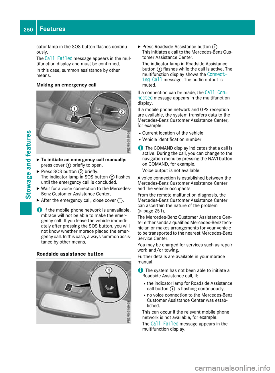
Making an emergency call
XTo initiate an emergency call manually:
press cover :briefly to open.
XPress SOS button ;briefly.
The indicator lamp in SOS button ;flashes
until the emergency call is concluded.
XWait for a voice connection to the Mercedes-
Benz Customer Assistance Center.
XAfter the emergency call, close cover :.
iIf the mobile phone network is unavailable,
mbrace will not be able to make the emer-
gency call. If you leave the vehicle immedi-
ately after pressing the SOS button, you will
not know whether mbrace placed the emer-
gency call. In this case, always summon assis-
tance by other means.
Roadside assistance button
XPress Roadside Assistance button :.
This initiates a call to the Mercedes-Benz Cus-
tomer Assistance Center.
The indicator lamp in Roadside Assistance
button :flashes while the call is active. The
multifunction display shows the Connect‐
ing Callmessage. The audio output is
muted.
If a connection can be made, the Call Con‐
nectedmessage appears in the multifunction
display.
If a mobile phone network and GPS reception
are available, the system transfers data to the
Mercedes-Benz Customer Assistance Center,
for example:
RCurrent location of the vehicle
RVehicle identification number
iThe COMAND display indicates that a call is
active. During the call, you can change to the
navigation menu by pressing the NAVI button
on COMAND, for example.
Voice output is not available.
A voice connection is established between the
Mercedes-Benz Customer Assistance Center
and the vehicle occupants.
From the remote malfunction diagnosis, the
Mercedes-Benz Customer Assistance Center
can ascertain the nature of the problem
(
Ypage 251).
The Mercedes-Benz Customer Assistance Cen-
ter either sends a qualified Mercedes-Benz tech-
nician or makes arrangements for your vehicle
to be transported to the nearest Mercedes-Benz
Service Center.
You may be charged for services such as repair
work and/or towing.
Further details are available in your mbrace
manual.
iThe system has not been able to initiate a
Roadside Assistance call, if:
Rthe indicator lamp for Roadside Assistance
call button :is flashing continuously.
Rno voice connection to the Mercedes-Benz
Customer Assistance Center was estab-
lished.
This can occur if the relevant mobile phone
network is not available, for example
.
The Call Failed
message appears in the
multifunction display.
250Features
Stowage and features
Page 253 of 322
XTo end a call:press the~button on the
multifunction steering wheel.
or
XPress the corresponding button for ending a
phone call on COMAND.
MB Info call button
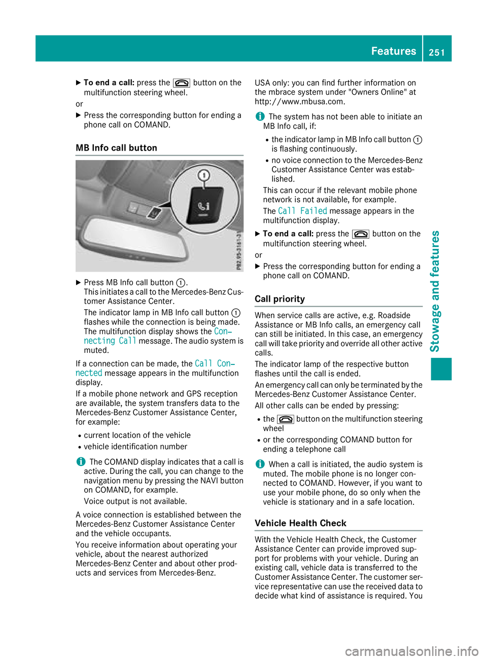
XPress MB Info call button :.
This initiates a call to the Mercedes-Benz Cus-
tomer Assistance Center.
The indicator lamp in MB Info call button :
flashes while the connection is being made.
The multifunction display shows the Con‐
nectingCallmessage. The audio system is
muted.
If a connection can be made, the Call Con‐
nectedmessage appears in the multifunction
display.
If a mobile phone network and GPS reception
are available, the system transfers data to the
Mercedes-Benz Customer Assistance Center,
for example:
Rcurrent location of the vehicle
Rvehicle identification number
iThe COMAND display indicates that a call is
active. During the call, you can change to the
navigation menu by pressing the NAVI button
on COMAND, for example.
Voice output is not available.
A voice connection is established between the
Mercedes-Benz Customer Assistance Center
and the vehicle occupants.
You receive information about operating your
vehicle, about the nearest authorized
Mercedes-Benz Center and about other prod-
ucts and services from Mercedes-Benz. USA only: you can find further information on
the mbrace system under "Owners Online" at
http://www.mbusa.co
m.
iThesystem ha s not been able to initiate an
MB Info call, if:
Rthe indicator lamp in MB Info call button :
is flashing continuously.
Rno voice connection to the Mercedes-Benz
Customer Assistance Center was estab-
lished.
This can occur if the relevant mobile phone
network is not available, for example.
The Call Failed
message appears in the
multifunction display.
XTo end a call: press the~button on the
multifunction steering wheel.
or
XPress the corresponding button for ending a
phone call on COMAND.
Call priority
When service calls are active, e.g. Roadside
Assistance or MB Info calls, an emergency call
can still be initiated. In this case, an emergency
call will take priority and override all other active
calls.
The indicator lamp of the respective button
flashes until the call is ended.
An emergency call can only be terminated by the
Mercedes-Benz Customer Assistance Center.
All other calls can be ended by pressing:
Rthe ~ button on the multifunction steering
wheel
Ror the corresponding COMAND button for
ending a telephone call
iWhen a call is initiated, the audio system is
muted. The mobile phone is no longer con-
nected to COMAND. However, if you want to
use your mobile phone, do so only when the
vehicle is stationary and in a safe location.
Vehicle Health Check
With the Vehicle Health Check, the Customer
Assistance Center can provide improved sup-
port for problems with your vehicle. During an
existing call, vehicle data is transferred to the
Customer Assistance Center. The customer ser-
vice representative can use the received data to
decide what kind of assistance is required. You
Features251
Stowag ean d features
Z
Page 279 of 322
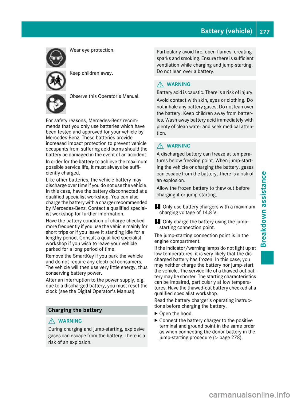
Wear eye protection.
Keep children away.
Observe this Operator's Manual.
For safety reasons, Mercedes-Benz recom-
mends that you only use batteries which have
been tested and approved for your vehicle by
Mercedes-Benz. These batteries provide
increased impact protection to prevent vehicle
occupants from suffering acid burns should the
battery be damaged in the event of an accident.
In order for the battery to achieve the maximum
possible service life, it must always be suffi-
ciently charged.
Like other batteries, the vehicle battery may
discharge over time if you do not use the vehicle.
In this case, have the battery disconnected at a
qualified specialist workshop. You can also
charge the battery with a charger recommended
by Mercedes-Benz. Contact a qualified special-
ist workshop for further information.
Have the battery condition of charge checked
more frequently if you use the vehicle mainly for
short trips or if you leave it standing idle for a
lengthy period. Consult a qualified specialist
workshop if you wish to leave your vehicle
parked for a long period of time.
Remove the SmartKey if you park the vehicle
and do not require any electrical consumers.
The vehicle will then use very little energy, thus conserving battery power.
After an interruption to the power supply, e.g.
due to a discharged battery, you must reset the
clock (see the Digital Operator's Manual).
Charging the battery
GWARNING
During charging and jump-starting, explosive
gases can escape from the battery. There is a risk of an explosion.
Particularly avoid fire, open flames, creating
sparks and smoking. Ensure there is sufficient
ventilation while charging and jump-starting.
Do not lean over a battery.
GWARNING
Battery acid is caustic. There is a risk of injury.
Avoid contact with skin, eyes or clothing. Do
not inhale any battery gases. Do not lean over
the battery. Keep children away from batter-
ies. Wash away battery acid immediately with
plenty of clean water and seek medical atten-
tion.
GWARNING
A discharged battery can freeze at tempera-
tures below freezing point. When jump-start-
ing the vehicle or charging the battery, gases can escape from the battery. There is a risk of
an explosion.
Allow the frozen battery to thaw out before
charging it or jump-starting.
!Only use battery chargers with a maximum
charging voltage of 14.8 V.
!Only charge the battery using the jump-
starting connection point.
The jump-starting connection point is in the
engine compartment.
If the indicator/warning lamps do not light up at
low temperatures, it is very likely that the dis-
charged battery has frozen. In this case, you
may neither charge the battery nor jump-start
the vehicle. The service life of a thawed-out bat-
tery may be shorter. The starting characteristics
can be impaired, particularly at low tempera-
tures. Have the thawed-out battery checked at a
qualified specialist workshop.
Read the battery charger's operating instruc-
tions before charging the battery.
XOpen the hood.
XConnect the battery charger to the positive
terminal and ground point in the same order
as when connecting the donor battery in the
jump-starting procedure (
Ypage 278).
Battery (vehicle)277
Breakdown assistance
Z