keyless MERCEDES-BENZ SL65AMG 2011 R230 Workshop Manual
[x] Cancel search | Manufacturer: MERCEDES-BENZ, Model Year: 2011, Model line: SL65AMG, Model: MERCEDES-BENZ SL65AMG 2011 R230Pages: 316, PDF Size: 7.21 MB
Page 271 of 316
Locking the vehicle
If you cannot lock the vehicle with the
SmartKey or with KEYLESS-GO, lock it as
follows:
XOpen the driver’s door.XClose the passenger door and the trunk.XPress the central locking switch
(Y page 73).
XCheck to see whether the locking knob on
the passenger door has moved down.
XIf necessary, push it down manually.XExit the vehicle and close the driver’s door.XRemove the mechanical key from the
SmartKey (Y page 267).
XCheck whether the trunk is locked.XIf it is not locked, lock it with the
mechanical key (Y page 77).
Except for the driver’s door, the vehicle
should now be locked.
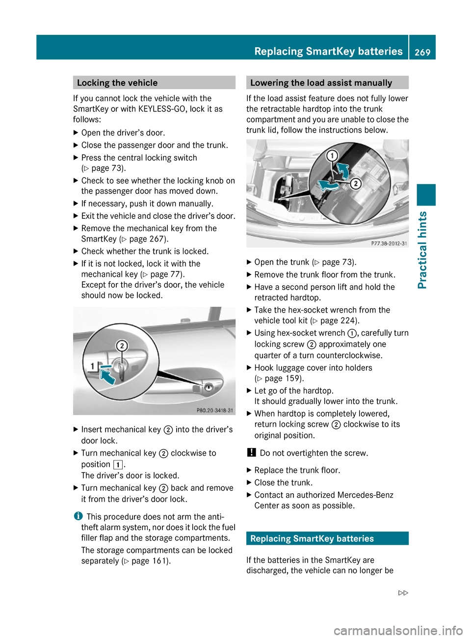
XInsert mechanical key ; into the driver’s
door lock.
XTurn mechanical key ; clockwise to
position 1.
The driver’s door is locked.
XTurn mechanical key ; back and remove
it from the driver’s door lock.
iThis procedure does not arm the anti-
theft alarm system, nor does it lock the fuel
filler flap and the storage compartments.
The storage compartments can be locked
separately (Y page 161).
Lowering the load assist manually
If the load assist feature does not fully lower
the retractable hardtop into the trunk
compartment and you are unable to close the
trunk lid, follow the instructions below.
XOpen the trunk (Y page 73).XRemove the trunk floor from the trunk.XHave a second person lift and hold the
retracted hardtop.
XTake the hex-socket wrench from the
vehicle tool kit (Y page 224).
XUsing hex-socket wrench :, carefully turn
locking screw ; approximately one
quarter of a turn counterclockwise.
XHook luggage cover into holders
(Y page 159).
XLet go of the hardtop.
It should gradually lower into the trunk.
XWhen hardtop is completely lowered,
return locking screw ; clockwise to its
original position.
! Do not overtighten the screw.
XReplace the trunk floor.XClose the trunk.XContact an authorized Mercedes-Benz
Center as soon as possible.
Replacing SmartKey batteries
If the batteries in the SmartKey are
discharged, the vehicle can no longer be
Replacing SmartKey batteries269Practical hints230_AKB; 6; 22, en-USd2ureepe,Version: 2.11.8.12009-07-28T18:49:58+02:00 - Seite 269Z
Page 273 of 316
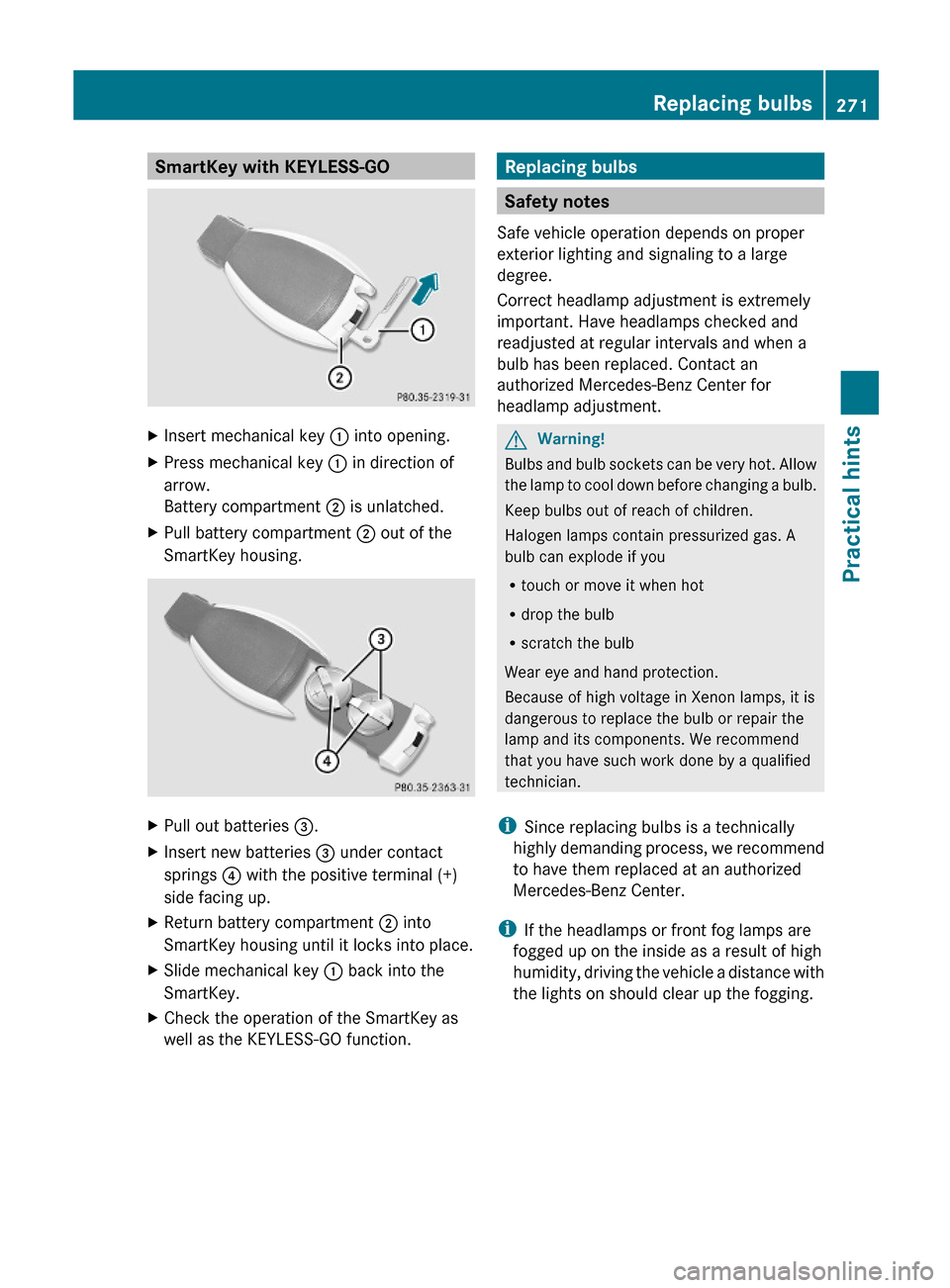
SmartKey with KEYLESS-GOXInsert mechanical key : into opening.XPress mechanical key : in direction of
arrow.
Battery compartment ; is unlatched.
XPull battery compartment ; out of the
SmartKey housing.
XPull out batteries =.XInsert new batteries = under contact
springs ? with the positive terminal (+)
side facing up.
XReturn battery compartment ; into
SmartKey housing until it locks into place.
XSlide mechanical key : back into the
SmartKey.
XCheck the operation of the SmartKey as
well as the KEYLESS-GO function.Replacing bulbs
Safety notes
Safe vehicle operation depends on proper
exterior lighting and signaling to a large
degree.
Correct headlamp adjustment is extremely
important. Have headlamps checked and
readjusted at regular intervals and when a
bulb has been replaced. Contact an
authorized Mercedes-Benz Center for
headlamp adjustment.
GWarning!
Bulbs and bulb sockets can be very hot. Allow
the lamp to cool down before changing a bulb.
Keep bulbs out of reach of children.
Halogen lamps contain pressurized gas. A
bulb can explode if you
Rtouch or move it when hot
Rdrop the bulb
Rscratch the bulb
Wear eye and hand protection.
Because of high voltage in Xenon lamps, it is
dangerous to replace the bulb or repair the
lamp and its components. We recommend
that you have such work done by a qualified
technician.
iSince replacing bulbs is a technically
highly demanding process, we recommend
to have them replaced at an authorized
Mercedes-Benz Center.
iIf the headlamps or front fog lamps are
fogged up on the inside as a result of high
humidity, driving the vehicle a distance with
the lights on should clear up the fogging.
Replacing bulbs271Practical hints230_AKB; 6; 22, en-USd2ureepe,Version: 2.11.8.12009-07-28T18:49:58+02:00 - Seite 271Z
Page 277 of 316
Replacing bulbs
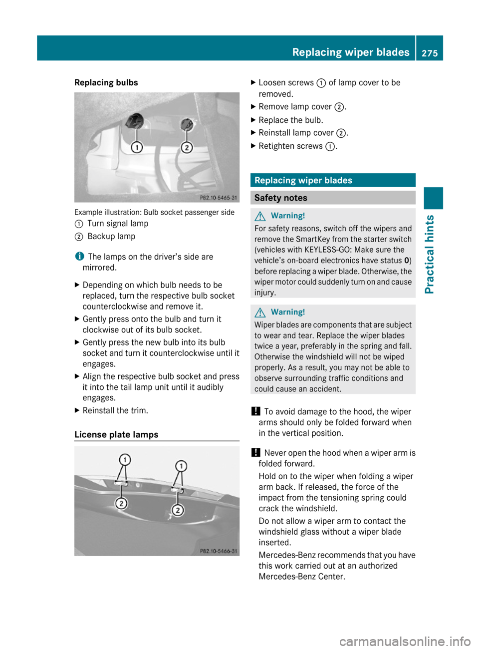
Example illustration: Bulb socket passenger side
:Turn signal lamp;Backup lamp
iThe lamps on the driver’s side are
mirrored.
XDepending on which bulb needs to be
replaced, turn the respective bulb socket
counterclockwise and remove it.
XGently press onto the bulb and turn it
clockwise out of its bulb socket.
XGently press the new bulb into its bulb
socket and turn it counterclockwise until it
engages.
XAlign the respective bulb socket and press
it into the tail lamp unit until it audibly
engages.
XReinstall the trim.
License plate lamps
XLoosen screws : of lamp cover to be
removed.
XRemove lamp cover ;.XReplace the bulb.XReinstall lamp cover ;.XRetighten screws :.
Replacing wiper blades
Safety notes
GWarning!
For safety reasons, switch off the wipers and
remove the SmartKey from the starter switch
(vehicles with KEYLESS-GO: Make sure the
vehicle’s on-board electronics have status 0)
before replacing a wiper blade. Otherwise, the
wiper motor could suddenly turn on and cause
injury.
GWarning!
Wiper blades are components that are subject
to wear and tear. Replace the wiper blades
twice a year, preferably in the spring and fall.
Otherwise the windshield will not be wiped
properly. As a result, you may not be able to
observe surrounding traffic conditions and
could cause an accident.
! To avoid damage to the hood, the wiper
arms should only be folded forward when
in the vertical position.
! Never open the hood when a wiper arm is
folded forward.
Hold on to the wiper when folding a wiper
arm back. If released, the force of the
impact from the tensioning spring could
crack the windshield.
Do not allow a wiper arm to contact the
windshield glass without a wiper blade
inserted.
Mercedes-Benz recommends that you have
this work carried out at an authorized
Mercedes-Benz Center.
Replacing wiper blades275Practical hints230_AKB; 6; 22, en-USd2ureepe,Version: 2.11.8.12009-07-28T18:49:58+02:00 - Seite 275Z
Page 278 of 316
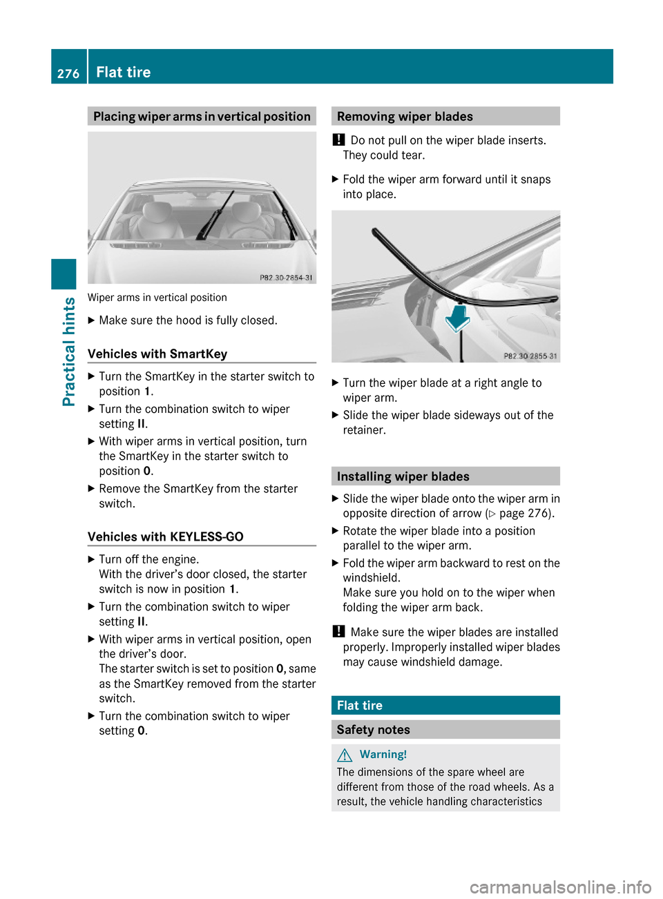
Placing wiper arms in vertical position
Wiper arms in vertical position
XMake sure the hood is fully closed.
Vehicles with SmartKey
XTurn the SmartKey in the starter switch to
position 1.
XTurn the combination switch to wiper
setting II.
XWith wiper arms in vertical position, turn
the SmartKey in the starter switch to
position 0.
XRemove the SmartKey from the starter
switch.
Vehicles with KEYLESS-GO
XTurn off the engine.
With the driver’s door closed, the starter
switch is now in position 1.
XTurn the combination switch to wiper
setting II.
XWith wiper arms in vertical position, open
the driver’s door.
The starter switch is set to position 0, same
as the SmartKey removed from the starter
switch.
XTurn the combination switch to wiper
setting 0.Removing wiper blades
! Do not pull on the wiper blade inserts.
They could tear.
XFold the wiper arm forward until it snaps
into place.
XTurn the wiper blade at a right angle to
wiper arm.
XSlide the wiper blade sideways out of the
retainer.
Installing wiper blades
XSlide the wiper blade onto the wiper arm in
opposite direction of arrow (Y page 276).
XRotate the wiper blade into a position
parallel to the wiper arm.
XFold the wiper arm backward to rest on the
windshield.
Make sure you hold on to the wiper when
folding the wiper arm back.
! Make sure the wiper blades are installed
properly. Improperly installed wiper blades
may cause windshield damage.
Flat tire
Safety notes
GWarning!
The dimensions of the spare wheel are
different from those of the road wheels. As a
result, the vehicle handling characteristics
276Flat tirePractical hints
230_AKB; 6; 22, en-USd2ureepe,Version: 2.11.8.12009-07-28T18:49:58+02:00 - Seite 276
Page 279 of 316
change when driving with a spare wheel
mounted. Adapt your driving style
accordingly.
The spare wheel is for temporary use only.
When driving with a spare wheel mounted,
ensure proper tire inflation pressure and do
not exceed a vehicle speed of 50 mph
(80 km/h).
Contact the nearest authorized Mercedes-
Benz Center as soon as possible to have the
spare wheel replaced with a regular road
wheel.
Never operate the vehicle with more than one
spare wheel mounted.
Do not switch off the ESP® when a spare
wheel is mounted.
Preparing the vehicle
XWhenever possible, park the vehicle in a
safe distance from moving traffic on a hard,
flat surface.
XTurn on the hazard warning flasher.XTurn the steering wheel so that the front
wheels are in a straight-ahead position.
XEngage the parking brake.XShift the automatic transmission into park
position P.
XTurn off the engine.XRemove the SmartKey from the starter
switch.
or
XVehicles with KEYLESS-GO: Open the
driver’s door (this puts the starter switch in
position 0, same as with the SmartKey
removed from the starter switch). The
driver’s door can then be closed again.
Open doors only when conditions are safe
to do so.
XHave any passenger exit the vehicle at a
safe distance from the roadway. Open
doors only when conditions are safe to do
so.
Mounting the spare wheel
Introduction
XPrepare the vehicle as described
(Y page 277).
XTake the following out of the vehicle:
Rspare wheel
Rjack
Rvehicle tool kit
Rwheel wrench
Relectric air pump
For information on where to find the
respective items, see “Where will I find ...?”
(Y page 224) and (Y page 225).
iVehicles without spare wheel are not
factory-equipped with the tools required for
a wheel change such as a jack or a wheel
wrench. Some tools required for a wheel
change are specific to your vehicle.
Contact an authorized Mercedes-Benz
Center to obtain the tools approved for
your vehicle. This section describes the
wheel change using the tools approved and
recommended for your vehicle.
Removing tensioning straps from spare
wheel
This description applies to vehicles with 19"
spare wheel with collapsible tire only.
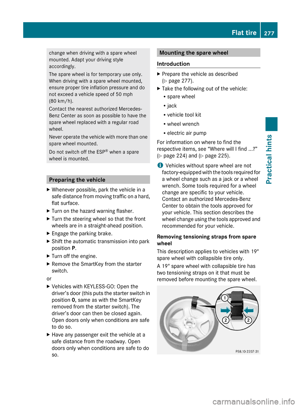
A 19" spare wheel with collapsible tire has
two tensioning straps on it that must be
removed before mounting the spare wheel.
Flat tire277Practical hints230_AKB; 6; 22, en-USd2ureepe,Version: 2.11.8.12009-07-28T18:49:58+02:00 - Seite 277Z
Page 283 of 316
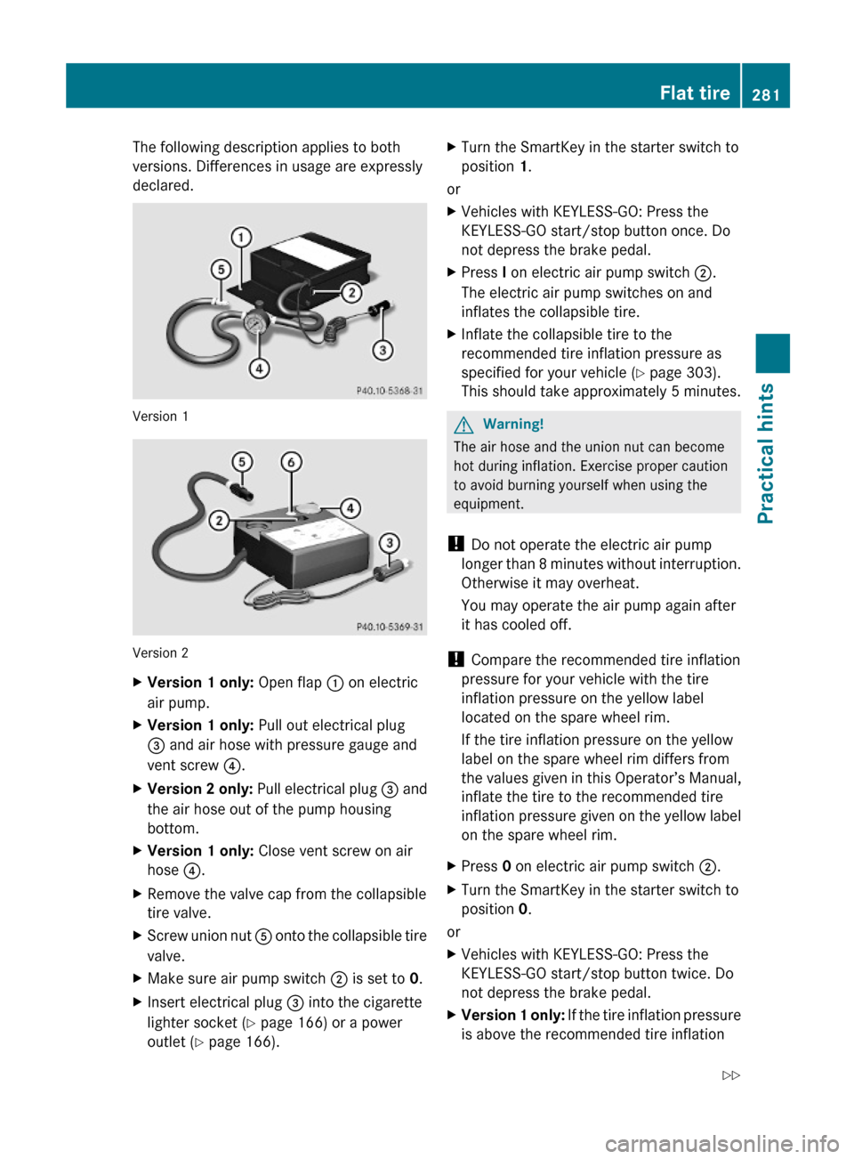
The following description applies to both
versions. Differences in usage are expressly
declared.
Version 1
Version 2
XVersion 1 only: Open flap : on electric
air pump.
XVersion 1 only: Pull out electrical plug
= and air hose with pressure gauge and
vent screw ?.
XVersion 2 only: Pull electrical plug = and
the air hose out of the pump housing
bottom.
XVersion 1 only: Close vent screw on air
hose ?.
XRemove the valve cap from the collapsible
tire valve.
XScrew union nut A onto the collapsible tire
valve.
XMake sure air pump switch ; is set to 0.XInsert electrical plug = into the cigarette
lighter socket (Y page 166) or a power
outlet (Y page 166).
XTurn the SmartKey in the starter switch to
position 1.
or
XVehicles with KEYLESS-GO: Press the
KEYLESS-GO start/stop button once. Do
not depress the brake pedal.
XPress I on electric air pump switch ;.
The electric air pump switches on and
inflates the collapsible tire.
XInflate the collapsible tire to the
recommended tire inflation pressure as
specified for your vehicle (Y page 303).
This should take approximately 5 minutes.
GWarning!
The air hose and the union nut can become
hot during inflation. Exercise proper caution
to avoid burning yourself when using the
equipment.
! Do not operate the electric air pump
longer than 8 minutes without interruption.
Otherwise it may overheat.
You may operate the air pump again after
it has cooled off.
! Compare the recommended tire inflation
pressure for your vehicle with the tire
inflation pressure on the yellow label
located on the spare wheel rim.
If the tire inflation pressure on the yellow
label on the spare wheel rim differs from
the values given in this Operator’s Manual,
inflate the tire to the recommended tire
inflation pressure given on the yellow label
on the spare wheel rim.
XPress 0 on electric air pump switch ;.XTurn the SmartKey in the starter switch to
position 0.
or
XVehicles with KEYLESS-GO: Press the
KEYLESS-GO start/stop button twice. Do
not depress the brake pedal.
XVersion 1 only: If the tire inflation pressure
is above the recommended tire inflation
Flat tire281Practical hints230_AKB; 6; 22, en-USd2ureepe,Version: 2.11.8.12009-07-28T18:49:58+02:00 - Seite 281Z
Page 287 of 316
The factory-equipped battery may only be
replaced with a battery that
R has the same security features
R is of identical size
R is of identical voltage
R is of identical capacity
! As any other battery, the battery may
discharge if you do not operate the vehicle
for an extended period of time. Have the
battery disconnected at a qualified
workshop or an authorized Mercedes-Benz
Center in such a case. You may also
connect an accessory battery charge unit
expressly approved by Mercedes-Benz for
your vehicle model to maintain the battery
charge. Contact an authorized Mercedes-
Benz Center for further information.
The battery, the battery ventilation hose
and the lateral plug must always be
securely installed when the vehicle is in
operation.
! Never loosen or detach battery terminal
clamps while the engine is running or the
SmartKey is in the starter switch or
KEYLESS-GO button is in position 1.
Otherwise the alternator and other
electronic components could be severely
damaged.
Have the battery checked regularly at an
authorized Mercedes-Benz Center.
Refer to Maintenance Booklet for
maintenance intervals or contact an
authorized Mercedes-Benz Center for
further information.
i After battery power was interrupted, do
the following:
R Synchronize the ESP ®
(Y page 228).
R Synchronize the power windows
( Y page 98).Charging the batteryGWarning!
Never charge a battery while still installed in
the vehicle unless the accessory battery
charge unit approved by Mercedes-Benz is
being used. Gases may escape during
charging and could cause an explosion that
may result in personal injury, paint damage or
corrosion.
An accessory battery charge unit specially
adapted for Mercedes-Benz vehicles and
tested and approved by Mercedes-Benz is
available. It permits the charging of the
battery in its installed position. Contact an
authorized Mercedes-Benz Center for
information and availability.
Charge battery in accordance with the
separate instructions for the accessory
battery charger.
Have the battery charged at an authorized
Mercedes-Benz Center. If you charge the
battery yourself, follow the operating
instructions for your charging device.
Only use a battery charge unit with a
maximum charging voltage of 14.8 V.
XCharge battery in accordance with the
instructions of the battery charger
manufacturer.
Jump starting
GWarning!
Failure to follow these directions will cause
damage to the electronic components, and
can lead to a battery explosion and severe
injury or death.
Never lean over batteries while connecting or
jump starting. You might get injured.
Battery fluid contains sulfuric acid. Do not
allow this fluid to come in contact with eyes,
skin or clothing. In case it does, immediately
Jump starting285Practical hints230_AKB; 6; 22, en-USd2ureepe,Version: 2.11.8.12009-07-28T18:49:58+02:00 - Seite 285Z
Page 292 of 316
Removing towing eye boltXLoosen towing eye bolt ; by turning it
counterclockwise.XUnscrew towing eye bolt ;.XReinstalling front cover: Fit locking tabs
of cover : (Y page 288) under the lower
edge of the opening in the bumper.XApply even pressure on the upper part of
the cover until it snaps into place.XReinstalling rear cover: Fit cover :
( Y page 288) and snap it into place.XStore the towing eye bolt ; and wheel
wrench back into the vehicle tool kit.
Towing with front axle raised
! The vehicle may be towed only for
distances up to 30 miles (50 km) and at a
speed not to exceed 30 mph (50 km/h).
XMake sure the ignition is switched on.XWith the vehicle at a standstill, depress the
brake pedal and keep it pressed.XShift the automatic transmission into
neutral position N.XRelease the brake pedal.XIf engaged, release the parking brake.XSwitch off the automatic central locking
( Y page 126).XSwitch off the ignition and leave the
SmartKey in the starter switch.XSwitch on the hazard warning flasher
( Y page 92).
!
Because the ESP ®
operates
automatically, the engine and ignition must
be shut off (SmartKey in starter switch
position 0 or 1 or KEYLESS-GO start/stop
button in position 0 or 1) when the vehicle
is being towed with the front axle raised.
Active braking action through the ESP ®
may otherwise seriously damage the brake
system which is not covered by the
Mercedes-Benz Limited Warranty.
Towing with all wheels on the groundGWarning!
If circumstances require towing the vehicle
with all wheels on the ground, always tow with
a tow bar if:
R the engine will not run
R there is a malfunction in the electro-
hydraulic brake system
R there is a malfunction in the power supply
or in the vehicle’s electrical system
This is necessary to adequately control the
towed vehicle.
Prior to towing the vehicle with all wheels on
the ground, make sure the SmartKey is in
starter switch position 2.
GWarning!
With the engine not running, there is no power
assistance for the brake and steering
systems. In this case, it is important to keep
in mind that a considerably higher degree of
effort is necessary to brake and steer the
vehicle. Adapt your driving accordingly.
XMake sure the ignition is switched on.XWith the vehicle at a standstill, depress the
brake pedal and keep it pressed.XShift the automatic transmission into
neutral position N.XRelease the brake pedal.XIf engaged, release the parking brake.XSwitch on the hazard warning flasher
( Y page 92).
!
The vehicle may be towed only for
distances up to 30 miles (50 km) and at a
speed not to exceed 30 mph (50 km/h).
i While being towed with the hazard
warning flasher in use, use the combination
switch in the usual manner to signal turns.
Only the selected turn signal will operate.
Upon canceling the turn signal, the hazard
warning flasher will operate again.
290Towing the vehiclePractical hints
230_AKB; 6; 22, en-USd2ureepe,Version: 2.11.8.12009-07-28T18:49:58+02:00 - Seite 290
Page 293 of 316
Fuses
Introduction
The electrical fuses in your vehicle serve to
switch off malfunctioning power circuits.
If a fuse is blown, the components and
systems secured by that fuse will stop
operating.
GWarning!
Only use fuses approved by Mercedes-Benz
with the specified amperage for the system in
question and do not attempt to repair or
bridge a blown fuse. Using other than
approved fuses or using repaired or bridged
fuses may cause an overload leading to a fire,
and/or cause damage to electrical
components and/or systems. Have the cause
determined and remedied by an authorized
Mercedes-Benz Center.
A blown fuse must be replaced by an
appropriate spare fuse (recognizable by its
color or the fuse rating given on the fuse) of
the amperage recommended in the fuse
chart. Any Mercedes-Benz Center will be glad
to advise you on this subject.
iIn case of a blown fuse contact Roadside
Assistance or an authorized Mercedes-
Benz Center.
If a newly inserted fuse blows again, have the
cause determined and rectified by an
authorized Mercedes-Benz Center.
The fuse chart is located in the trunk with the
vehicle tool kit (Y page 224). The fuse chart
explains the fuse allocation and fuse
amperages.
Before replacing fuses
XEngage the parking brake.XMake sure the automatic transmission is in
park position P.
XSwitch off all electrical consumers.XTurn off the engine.XRemove the SmartKey from the starter
switch.
XVehicles with KEYLESS-GO: Open the
driver’s door (this puts the starter switch in
position 0, same as with the SmartKey
removed from the starter switch). The
driver’s door then can be closed again.
Fuse box in passenger compartment
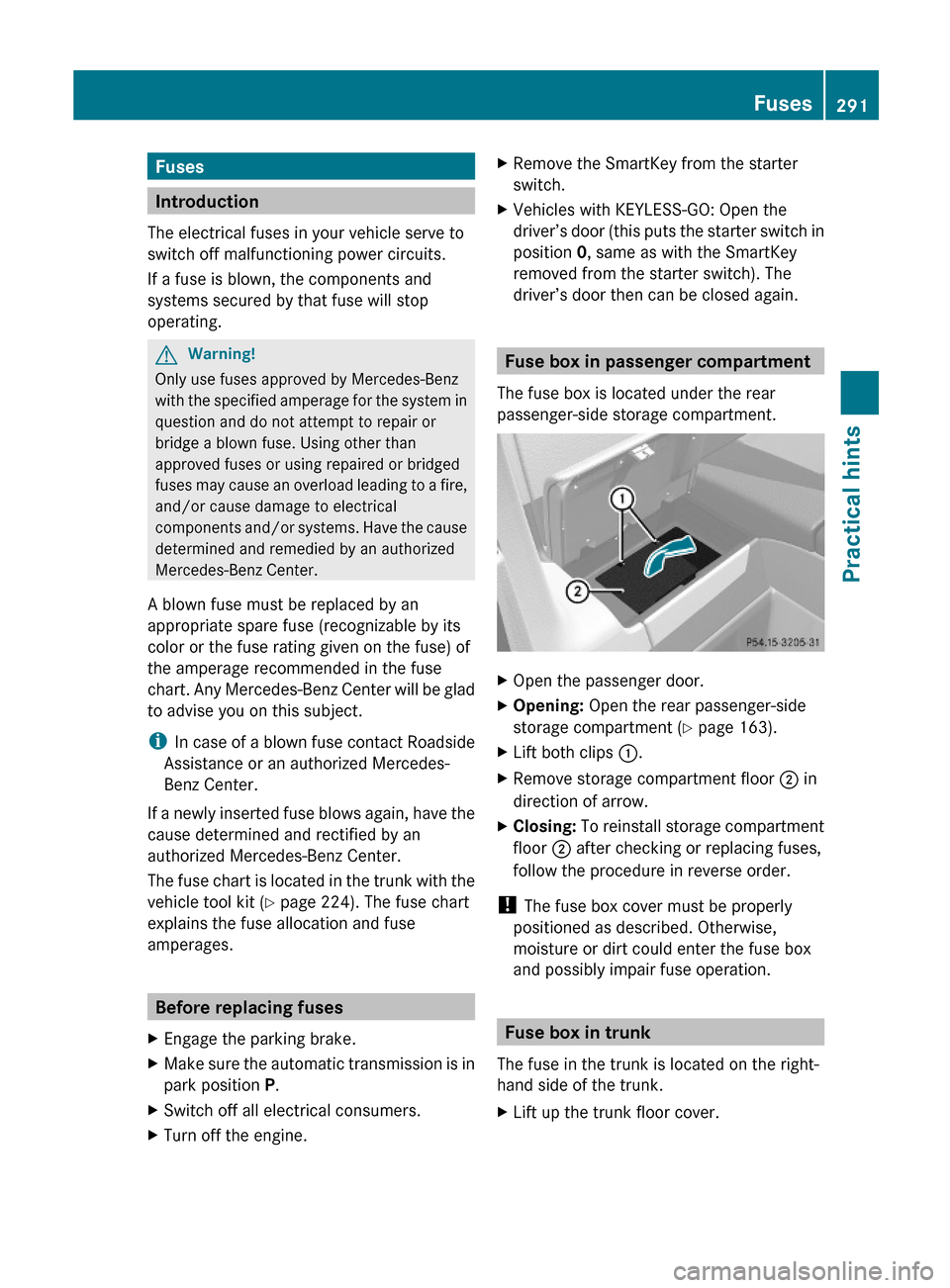
The fuse box is located under the rear
passenger-side storage compartment.
XOpen the passenger door.XOpening: Open the rear passenger-side
storage compartment (Y page 163).
XLift both clips :.XRemove storage compartment floor ; in
direction of arrow.
XClosing: To reinstall storage compartment
floor ; after checking or replacing fuses,
follow the procedure in reverse order.
! The fuse box cover must be properly
positioned as described. Otherwise,
moisture or dirt could enter the fuse box
and possibly impair fuse operation.
Fuse box in trunk
The fuse in the trunk is located on the right-
hand side of the trunk.
XLift up the trunk floor cover.Fuses291Practical hints230_AKB; 6; 22, en-USd2ureepe,Version: 2.11.8.12009-07-28T18:49:58+02:00 - Seite 291Z