MERCEDES-BENZ SLK 230 KOMPRESSOR 2002 R170 Owner's Manual
Manufacturer: MERCEDES-BENZ, Model Year: 2002, Model line: SLK 230 KOMPRESSOR, Model: MERCEDES-BENZ SLK 230 KOMPRESSOR 2002 R170Pages: 290, PDF Size: 20.03 MB
Page 211 of 290
208 Tires, wheels
Te ch n i c a l
data Instruments
and controlsOperation DrivingInstrument
cluster displayPractical hintsCar care Index
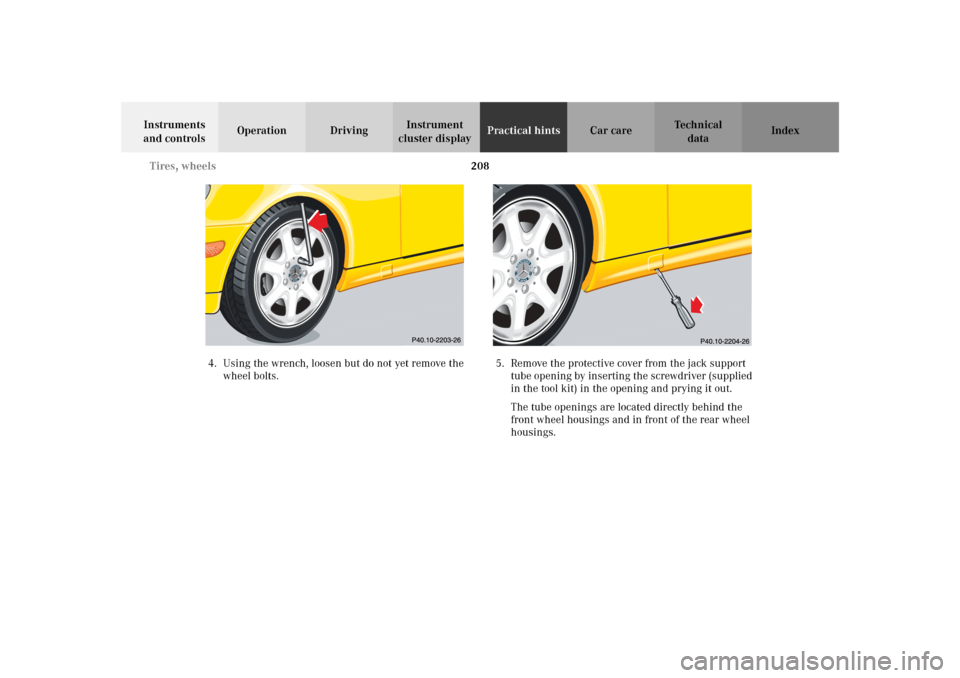
4. Using the wrench, loosen but do not yet remove the
wheel bolts.5. Remove the protective cover from the jack support
tube opening by inserting the screwdriver (supplied
in the tool kit) in the opening and prying it out.
The tube openings are located directly behind the
front wheel housings and in front of the rear wheel
housings.
Page 212 of 290
209 Tires, wheels
Te ch n i c a l
data Instruments
and controlsOperation DrivingInstrument
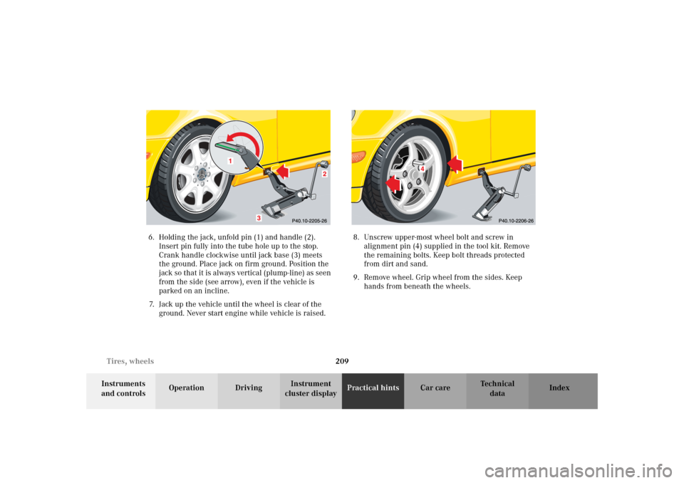
cluster displayPractical hintsCar care Index 6. Holding the jack, unfold pin (1) and handle (2).
Insert pin fully into the tube hole up to the stop.
Crank handle clockwise until jack base (3) meets
the ground. Place jack on firm ground. Position the
jack so that it is always vertical (plump-line) as seen
from the side (see arrow), even if the vehicle is
parked on an incline.
7. Jack up the vehicle until the wheel is clear of the
ground. Never start engine while vehicle is raised.8. Unscrew upper-most wheel bolt and screw in
alignment pin (4) supplied in the tool kit. Remove
the remaining bolts. Keep bolt threads protected
from dirt and sand.
9. Remove wheel. Grip wheel from the sides. Keep
hands from beneath the wheels.
Page 213 of 290
210 Tires, wheels
Te ch n i c a l
data Instruments
and controlsOperation DrivingInstrument
cluster displayPractical hintsCar care Index
Important!
For ease of handling and proper unfolding of tire during
its inflation when installing spare wheel with
collapsible tire, first mount the spare wheel, then inflate
the tire.
10. Clean contact surfaces of wheel and wheel hub.
Install wheel on wheel hub. Insert proper wheel
bolts and tighten them snugly.
Unscrew the alignment pin (4) to install the last
wheel bolt.
11. Inflate collapsible spare tire. (See next page for
detailed instructions).Important!
When installing spare wheel with collapsible tire, make
certain to use the correct wheel bolts, supplied in the
vehicle tool kit.
To avoid paint damage, place wheel flat against hub and
hold it there while installing first wheel bolt.
12. Lower vehicle. Remove jack and insert jack tube
cover.
Page 214 of 290
211 Tires, wheels
Te ch n i c a l
data Instruments
and controlsOperation DrivingInstrument
cluster displayPractical hintsCar care Index Notes:
Before storing the jack, it should be fully collapsed, with
pin and handle folded in.
The removed road wheel can be stored under the
luggage cover in a protective cover supplied with
vehicle. The collapsible spare wheel should be returned
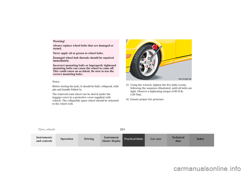
to the wheel well.13. Using the wrench, tighten the five bolts evenly,
following the sequence illustrated, until all bolts are
tight. Observe a tightening torque of 80 ft.lb.
(110 Nm).
14. Ensure proper tire pressure.
Wa r n i n g !
Always replace wheel bolts that are damaged or
rusted.Never apply oil or grease to wheel bolts.Damaged wheel hub threads should be repaired
immediately.Incorrect mounting bolts or improperly tightened
mounting bolts can cause the wheel to come off.
This could cause an accident. Be sure to use the
correct mounting bolts.
Page 215 of 290
212 Tires, wheels
Te ch n i c a l
data Instruments
and controlsOperation DrivingInstrument
cluster displayPractical hintsCar care Index
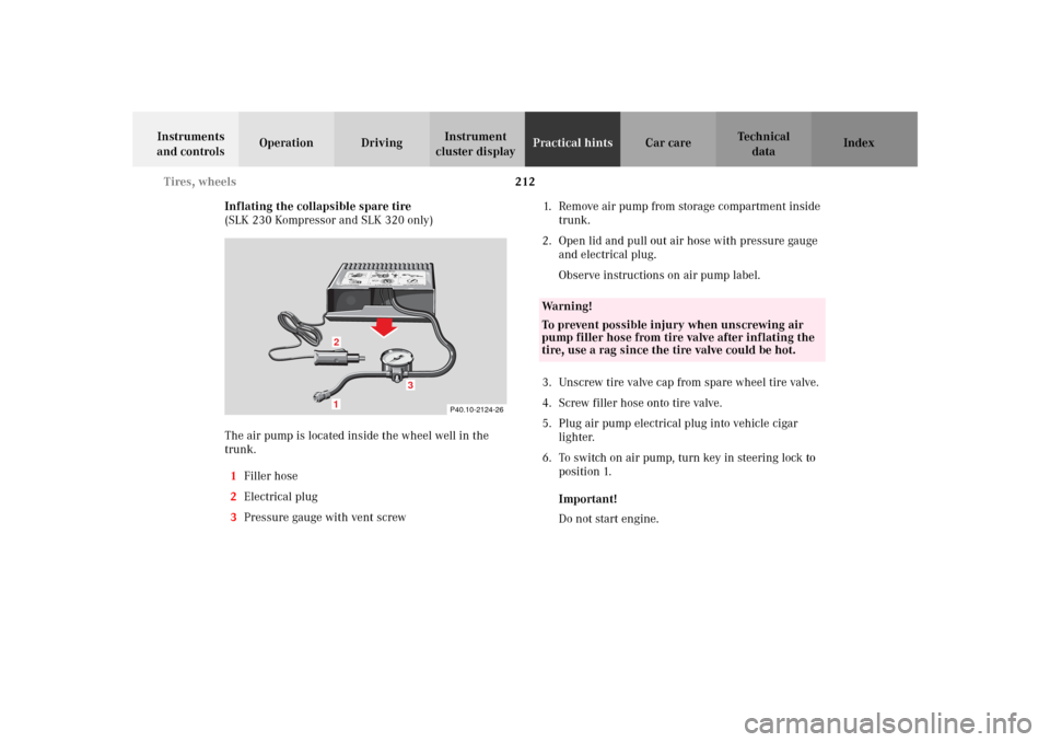
Inflating the collapsible spare tire
(SLK 230 Kompressor and SLK 320 only)
The air pump is located inside the wheel well in the
trunk.
1Filler hose
2Electrical plug
3Pressure gauge with vent screw1. Remove air pump from storage compartment inside
trunk.
2. Open lid and pull out air hose with pressure gauge
and electrical plug.
Observe instructions on air pump label.
3. Unscrew tire valve cap from spare wheel tire valve.
4. Screw filler hose onto tire valve.
5. Plug air pump electrical plug into vehicle cigar
lighter.
6. To switch on air pump, turn key in steering lock to
position 1.
Important!
Do not start engine.
P40.10-2124-26
1
0
45 6max. 6 min
A 170 584 01 38 AIR COMPRESSOR 23
Mercedes-Benz
2
3
2 1
1
2,5 bar
36 psi1
0 23
4
5
620PSI
BAR40
60
80
LUFTPRESSER12
12
3
Wa r n i n g !
To prevent possible injury when unscrewing air
pump filler hose from tire valve after inflating the
tire, use a rag since the tire valve could be hot.
Page 216 of 290
213 Tires, wheels
Te ch n i c a l
data Instruments
and controlsOperation DrivingInstrument
cluster displayPractical hintsCar care Index 7. Operate air pump (approximately 5 minutes) until
pressure gauge displays 36 psi (2.5 bar).
8. To switch off air pump, turn key in steering lock to
position 0.
9. Unscrew filler hose from tire. Reinstall tire valve
cap.
Note:
Excessive tire air pressure should be released using the
vent screw.Storing spare wheel in wheel well
Deflate spare tire:
1. Unscrew valve stem removal tool, which is a part of
the valve cap, from tire valve.
2. Using the valve stem removal tool, open tire valve
slightly by turning the tire valve insert
counterclockwise to release air pressure.
3. When the tire air pressure has been released,
remove tire valve insert (protect it from dirt and
sand) using the previously removed tire valve cap.
4. Once all air is out of the tire, and the tire has
collapsed to its original shape, reinstall the tire
valve insert and valve cap.
Place spare wheel in wheel well and secure it with air
pump holder. Turn pump holder clockwise to its stop.
Page 217 of 290
214 Tires, wheels
Te ch n i c a l
data Instruments
and controlsOperation DrivingInstrument
cluster displayPractical hintsCar care Index
TIREFIT
(SLK 32 AMG only)
Small punctures, particularly those in the tread can be
sealed with TIREFIT.
Foreign objects (e.g. screws or nails) should not be
removed from the tire.
TIREFIT can be used in ambient temperatures down to
approx. - 4°F (- 20°C).
Wa r n i n g !
Cuts or punctures larger than approx. 0.16 in
(4 mm), tire damage caused by driving with
extremely low tire pressure or on a flat tire, or a
damaged wheel can pose a hazard while driving.
TIREFIT should not be used in such circumstances.Do not drive the vehicle under such circumstances.Contact your nearest Mercedes-Benz Center for
assistance.Take care not to allow the contents of TIREFIT to
come in contact with hair, eyes or clothing.
TIREFIT is harmful if inhaled, swallowed or
absorbed through the skin - causes skin, eye and
respiratory irritation.
Any contact with eyes or skin should be flushed
immediately with plenty of water.If clothing comes in contact with TIREFIT, change
clothing as soon as possible.In case of allergic reaction or rash, consult a
physician immediately.Keep TIREFIT out of reach of children.
If swallowed, rinse mouth immediately with plenty
of water and drink plenty of water.Do not induce vomiting!Consult a physician immediately.Keep away from open flame or heat source.
Page 218 of 290
215 Tires, wheels
Te ch n i c a l
data Instruments
and controlsOperation DrivingInstrument
cluster displayPractical hintsCar care Index Sealing tire with TIREFIT
1. Set parking brake and turn on hazard warning
flasher.
2. Move selector lever to position “P” and turn off
engine.
3. Take TIREFIT out of storage box, see page 202.
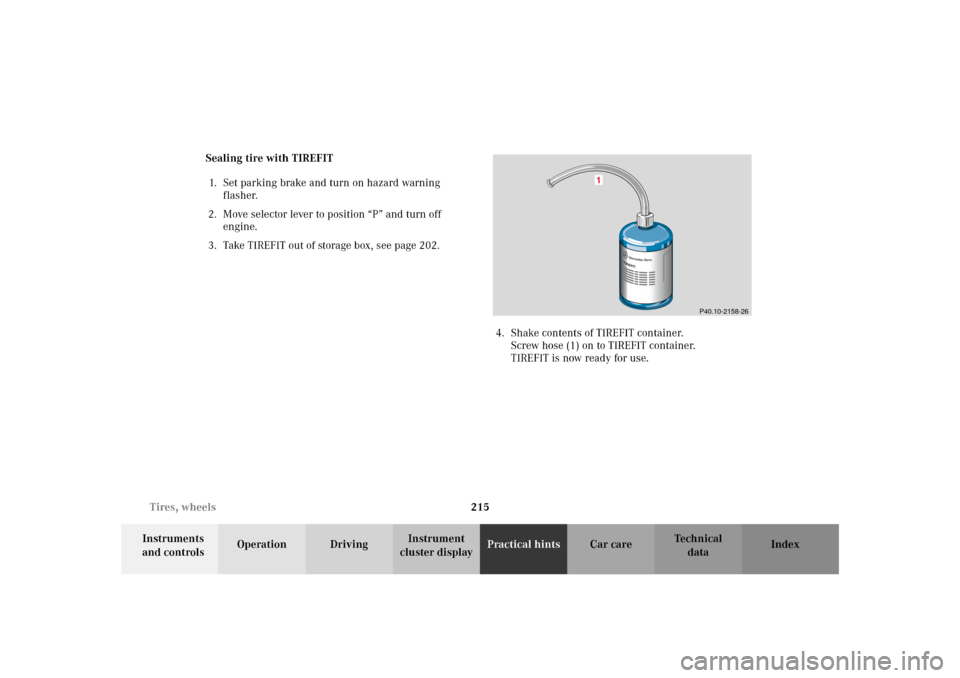
4. Shake contents of TIREFIT container.
Screw hose (1) on to TIREFIT container.
TIREFIT is now ready for use.
1
P40.10-2158-26
Page 219 of 290
216 Tires, wheels
Te ch n i c a l
data Instruments
and controlsOperation DrivingInstrument
cluster displayPractical hintsCar care Index
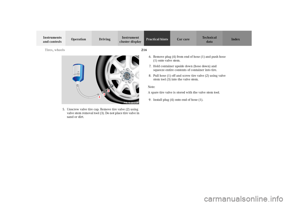
5. Unscrew valve tire cap. Remove tire valve (2) using
valve stem removal tool (3). Do not place tire valve in
sand or dirt.6. Remove plug (4) from end of hose (1) and push hose
(1) onto valve stem.
7. Hold container upside down (hose down) and
squeeze entire contents of container into tire.
8. Pull hose (1) off and screw tire valve (2) using valve
stem tool (3) into the valve stem.
Note:
A spare tire valve is stored with the valve stem tool.
9. Install plug (4) onto end of hose (1).
Page 220 of 290
217 Tires, wheels
Te ch n i c a l
data Instruments
and controlsOperation DrivingInstrument
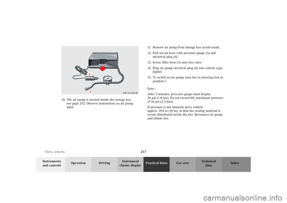
cluster displayPractical hintsCar care Index 10. The air pump is located inside the storage box,
see page 202. Observe instructions on air pump
label.11. Remove air pump from storage box inside trunk.
12. Pull out air hose with pressure gauge (5) and
electrical plug (6).
13. Screw filler hose (5) onto tire valve.
14. Plug air pump electrical plug (6) into vehicle cigar
lighter.
15. To switch on air pump, turn key in steering lock to
position 1.
Note:
After 5 minutes, pressure gauge must display
26 psi (1.8 bar). Do not exceed the maximum pressure
of 36 psi (2.5 bar)!
If pressure is not attained, drive vehicle
approx. 394 in (10 m), so that the sealing material is
evenly distributed inside the tire. Reconnect air pump
and inflate tire.
P40.10-2160-26
65