MERCEDES-BENZ SLK-CLASS ROADSTER 2015 Owners Manual
Manufacturer: MERCEDES-BENZ, Model Year: 2015, Model line: SLK-CLASS ROADSTER, Model: MERCEDES-BENZ SLK-CLASS ROADSTER 2015Pages: 358, PDF Size: 40.28 MB
Page 331 of 358
ratio is calculated by dividing the tire width by
the tire height.
Tire code: tire code=specifies the tire type.
"R" represents radial tires; "D" represents
diagonal tires; "B" represents diagonal radialtires.
Optionally, tires with a maximum speed of
over 149 mph (240 km/h) may have "ZR" in
the size description, depending on the man-
ufacturer (e.g. 245/40 ZR 18).
Rim diameter: rim diameter?is the diam-
eter of the bead seat, not the diameter of the
rim flange. The rim diameter is specified in
inches (in).
Load-bearing index: load-bearing indexA
is a numerical code that specifies the maxi-
mum load-bearing capacity of a tire.
Do not overload the tires by exceeding the
specified load limit. The maximum permissi-
ble load can be found on the vehicle's Tire and Loading Information placard on the B-pillar on the driver's side ( Ypage 323).
Example:
Load-bearing index 91 indicates a maximum
load of 1,356 lb (615 kg) that the tires can
bear. For further information on the maximum
tire load in kilograms and lbs, see( Y page 330).
For further information on the load bearing
index, see "Load index" ( Ypage 330).
Speed rating: speed ratingBspecifies the
approved maximum speed of the tire.
iTire data is vehicle-specific and may devi-
ate from the data in the example.
Regardless of the speed rating, always
observe the speed limits. Drive carefully and
adapt your driving style to the traffic condi-tions.
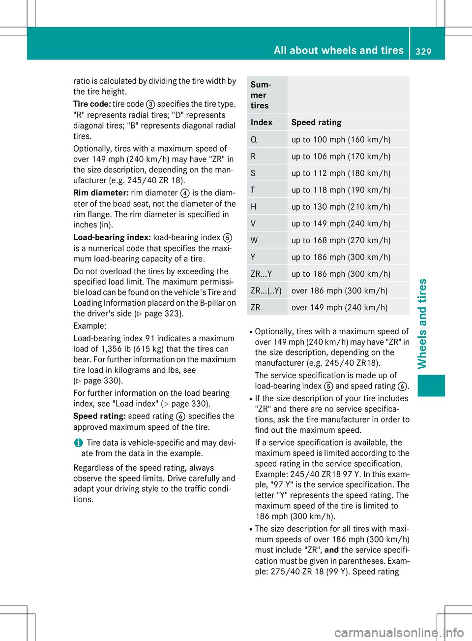
Sum- mertires
IndexSpeed rating
Qup to 100 mph (160 km/h)
Rup to 106 mph (170 km/h)
Sup to 112 mph (180 km/h)
Tup to 118 mph (190 km/h)
Hup to 130 mph (210 km/h)
Vup to 149 mph (240 km/h)
Wup to 168 mph (270 km/h)
Yup to 186 mph (300 km/h)
ZR...Yup to 186 mph (300 km/h)
ZR...(..Y)over 186 mph (300 km/h)
ZRover 149 mph (240 km/h)
R Optionally, tires with a maximum speed of
over 149 mph (240 km/h) may have "ZR" in
the size description, depending on the
manufacturer (e.g. 245/40 ZR18).
The service specification is made up of
load-bearing index Aand speed rating B.
R If the size description of your tire includes
"ZR" and there are no service specifica-
tions, ask the tire manufacturer in order to
find out the maximum speed.
If a service specification is available, the
maximum speed is limited according to the
speed rating in the service specification.
Example: 245/40 ZR18 97 Y.In this exam-
ple, "97 Y" is the service specification. The letter "Y" represents the speed rating. The
maximum speed of the tire is limited to
186 mph (300 km/h).
R The size description for all tires with maxi-
mum speeds of over 186 mph (300 km/h)
must include "ZR", andthe service specifi-
cation must be given in parentheses. Exam- ple: 275/40 ZR 18 (99 Y). Speed rating
All about wheels and tires329
Wheels and tires
Z
Page 332 of 358
\" indicates that the maximum speed of
the tire is over 186 mph (300 km/h). Ask
the tire manufacturer about the maximum
speed.
All-
weather
tires
and win-
ter tires
IndexSpeed rating
Q M+")
"(Y)" indicates that the maximum speed of
the tire is over 186 mph (300 km/h). Ask
the tire manufacturer about the maximum
speed.
All-
weather
tires
and win-
ter tires
IndexSpeed rating
Q M+S 3up to 100 mph (160 km/h)
T M+S3up to 118 mph (190 km/h)
H M+S
3up to 130 mph (210 km/h)
V M+S3up to 149 mph (240 km/h)
iNot all tires with the M+S marking provide
the driving characteristics of winter tires. In
addition to the M+S marking, winter tires
also have the isnowflake symbol on
the tire wall. Tires with this marking fulfill
the requirements of the Rubber Manufac-
turers Association (RMA) and the Rubber
Association of Canada (RAC) regarding the
tire traction on snow. They have been espe- cially developed for driving on snow.
An electronic speed limiter prevents your
vehicle from exceeding the following speeds:
R All vehicles (except AMG vehicles):
130 mph (210 km/h)
R AMG vehicles: 155 mph (250 km/h)
R AMG vehicles with Handling Package:
174 mph (280 km/h)
The speed rating of tires mounted at the fac- tory may be higher than the maximum speed
that the electronic speed limiter permits.
Make sure that your tires have the required
speed rating, e.g. when buying new tires. Therequired speed rating for your vehicle can be
found in the "tires" section ( Ypage 339). Further information about reading tire data
can be obtained from any qualified specialist
workshop.
Load index
In addition to the load bearing index, load rat-
ing :may be imprinted after the letters that
identify speed rating on the sidewall of the tire
( Y page 328).
R If no specification is given: no text (as in the
example above), represents a standard
load (SL) tire
R XL or Extra Load: represents a reinforced
tire
R Light Load: represents a light load tire
R C, D, E: represents a load range that
depends on the maximum load that the tire
can carry at a certain pressure
iTire data is vehicle-specific and may devi-
ate from the data in the example.
Maximum load rating
3 Or M+S ifor winter tires.
330All about wheels and tires
Wheels and ti res
Page 333 of 358

Maximum load rating:is the maximum per-
missible weight for which the tire is approved.
Do not overload the tires by exceeding the
specified load limit. The maximum permissi-
ble load can be found on the vehicle's Tire and Loading Information placard on the B-pillar on the driver's side ( Ypage 323).
iThe actual values for tires are vehicle-
specific and may deviate from the values in
the illustration.
DOT, Tire Identification Number (TIN)
U.S. tire regulations prescribe that every tire
manufacturer or retreader must imprint a TIN in or on the sidewall of every tire produced.
The TIN is a unique identification number. The
TIN makes it easier for tire manufacturers or
retreaders to notify customers of recalls or
other safety-related matters. It makes it pos- sible for the purchaser to easily identify the
affected tires.
The TIN consists of the manufacturer identi-
fication code ;, tire size =, tire type
code ?and manufacturing date A.
DOT (Department of Transportation): tire
symbol :indicates that the tire complies
with the requirements of the U.S. Department
of Transportation.
Manufacturer identification code: manu-
facturer identification code ;provides
details on the tire manufacturer. New tires
have a code with two symbols. Retreaded
tires have a code with four symbols. For further information about retreaded tires,
see (
Ypage 312).
Tire size: identifier=describes the tire size.
Tire type code: tire type code?can be used
by the manufacturer as a code to describe
specific characteristics of the tire.
Date of manufacture: date of manufacture
A provides information about the age of a
tire. The first and second positions represent the week of manufacture, starting with "01"
for the first calendar week. Positions three
and four represent the year of manufacture.
For example, a tire that is marked with
"3208", was manufactured in week 32 in2008.
iTire data is vehicle-specific and may devi-
ate from the data in the example.
Tire characteristics
This information describes the type of tire
cord and the number of layers in sidewall :
and under tire tread ;.
iTire data is vehicle-specific and may devi-
ate from the data in the example.
Definition of terms for tires and loading
Tire ply composition and material used
Describes the number of plies or the number of layers of rubber-coated fabric in the tire
tread and sidewall. These are made of steel,
nylon, polyester and other materials.
All about wheels and tires331
Wheels and tires
Z
Page 334 of 358
 and 100 kilopascals
(kPa) are the equivalent of 1 bar.
DOT (Department of Transportation)
DOT marked tires fulfill the requir")
Bar
Metric unit for tire pressure. 14.5038 poundsper square inch (psi) and 100 kilopascals
(kPa) are the equivalent of 1 bar.
DOT (Department of Transportation)
DOT marked tires fulfill the requirements of
the United States Department of Transporta-tion.
Normal occupant weight
The number of occupants which the vehicle is
designed for, multiplied by 68 kilograms
(150 lb).
Uniform Tire Quality Grading Standards
A uniform standard to grade the quality of
tires with regards to tread quality, tire traction and temperature characteristics. Ratings are
determined by tire manufacturers using U.S.
government testing procedures. The ratings
are molded into the sidewall of the tire.
Recommended tire pressure
The recommended tire pressure applies to
the tires mounted at the factory.
The Tire and Loading Information placard con- tains the recommended tire pressures for
cold tires on a fully loaded vehicle and for themaximum permissible vehicle speed.
The tire pressure table contains the recom-
mended pressures for cold tires for various
operating conditions, i.e. differing load and
speed conditions.
Increased vehicle weight due to optional
equipment
This is the combined weight of all standard
and optional equipment available for the vehi-
cle, regardless of whether it is actually instal-
led on the vehicle or not. Rim
This is the part of the wheel on which the tire
is mounted. GAWR (Gross Axle Weight Rating)
The GAWR is the maximum permissible axle
weight. The actual load on an axle must never
exceed the gross axle weight rating. The
gross axle weight rating can be found on the
vehicle identification plate on the B-pillar on
the driver's side.
Speed rating
The speed rating is part of the tire identifica-
tion. It specifies the speed range for which the
tire is approved.
GVW (Gross Vehicle Weight)
The gross vehicle weight includes the weight
of the vehicle including fuel, tools, the spare
wheel, accessories installed, occupants, lug-
gage and the drawbar noseweight, if applica-
ble. The gross vehicle weight must not exceed the gross vehicle weight rating GVWR as
specified on the vehicle identification plate on
the B pillar on the driver's side.
GVWR (Gross Vehicle Weight Rating)
The GVWR is the maximum permissible gross weight of a fully loaded vehicle (the weight of the vehicle including all accessories, occu-
pants, fuel, luggage and the drawbar nose-
weight, if applicable). The gross vehicle
weight rating is specified on the vehicle iden-
tification plate on the B-pillar on the driver's
side.
Maximum loaded vehicle weight
The maximum weight is the sum of:
R the curb weight of the vehicle
R the weight of the accessories
R the load limit
R the weight of the factory installed optional
equipment
Kilopascal (kPa)
Metric unit for tire pressure. 6.9 kPa corre-
sponds to 1 psi. Another unit for tire pressure is bar. There are 100 kilopascals (kPa) to
1 bar.
332All about wheels and tires
Wheels and tires
Page 335 of 358

Load index
In addition to the load-bearing index, the loadindex may also be imprinted on the sidewall ofthe tire. This specifies the load-bearing capa-
city more precisely.
Curb weight
The weight of a vehicle with standard equip-
ment including the maximum capacity of fuel, oil and coolant. It also includes the air-condi- tioning system and optional equipment if
these are installed in the vehicle, but does not
include passengers or luggage.
Maximum load rating
The maximum tire load is the maximum per-
missible weight in kilograms or lbs for which a
tire is approved.
Maximum permissible tire pressure
Maximum permissible tire pressure for one
tire.
Maximum load on one tire
Maximum load on one tire. This is calculated
by dividing the maximum axle load of one axle by two.
PSI (pounds per square inch)
A standard unit of measure for tire pressure.
Aspect ratio
Relationship between tire height and tire
width in percent.
Tire pressure
This is pressure inside the tire applying an
outward force to each square inch of the tire's
surface. The tire pressure is specified in
pounds per square inch (psi), in kilopascal
(kPa) or in bar. The tire pressure should only
be corrected when the tires are cold. Cold tire pressure
The tires are cold:
R if the vehicle has been parked without
direct sunlight on the tires for at least three
hours and
R if the vehicle has been driven for less than
1 mile (1.6 km).
Tread
The part of the tire th at comes into contact
with the road.
Bead
The tire bead ensures that the tire sits
securely on the wheel. There are several steel
wires in the bead to prevent the tire from
coming loose from the wheel rim.
Sidewall
The part of the tire between the tread and the
bead.
Weight of optional extras
The combined weight of those optional extras that weigh more than the replaced standard
parts and more than 2.3 kilograms (5 lbs).
These optional extras, such as high-perform-
ance brakes, level control, a roof rack or a
high-performance battery, are not included in
the curb weight and the weight of the acces-
sories.
TIN (Tire Identification Number)
This is a unique identifier which can be used
by a tire manufacturer to identify tires, for
example for a product recall, and thus identify the purchasers. The TIN is made up of the
manufacturer's identity code, tire size, tire
type code and the manufacturing date.
Load bearing index
The load bearing index (also load index) is a
code that contains the maximum load bearing capacity of a tire.
All about wheels and tires333
Wheels and tires
Z
Page 336 of 358
 that are dis-
tributed over the tire tread. If the tire trea")
Traction
Traction is the result of friction between the
tires and the road surface.
Treadwear indicators
Narrow bars (tread wear bars) that are dis-
tributed over the tire tread. If the tire tread islevel with the bars, the wear limit of áin
(1.6 mm) has been reached.
Occupant distribution
The distribution of occupants in a vehicle at
their designated seating positions.
Total load limit
Rated cargo and luggage load plus
68 kilograms (150 lb) multiplied by the num-
ber of seats in the vehicle.
Changing a wheel
Flat tire
The "Breakdown assistance" section ( Y page 295) contains information and notes
on how to deal with a flat tire. Information on driving with MOExtended tires in the event of
a flat tire can be found under "MOExtended
tires (tires with run-flat characteristics"( Y page 295).
Rotating the wheels
GWARNING
Interchanging the front and rear wheels may
severely impair the driving characteristics if
the wheels or tires have different dimensions.
The wheel brakes or suspension components
may also be damaged. There is a risk of acci-
dent.
Rotate front and rear wheels only if the wheels and tires are of the same dimensions.
!On vehicles equipped with a tire pressure
monitor, electronic components are loca-
ted in the wheel. Tire-mounting tools should not be used
near the valve. This could damage the elec-
tronic components.
Only have tires changed at a qualified spe-cialist workshop.
Always pay attention to the instructions and
safety notes when changing a wheel( Y page 335).
The wear patterns on the front and rear tires
differ, depending on the operating conditions.
Rotate the wheels before a clear wear pattern has formed on the tires. Front tires typically
wear more on the shoulders and the rear tires in the center.
If your vehicle's tire configuration allows, you can rotate the wheels according to the inter-
vals in the tire manufacturer's warranty book
in your vehicle documents. If no warranty
book is available, the tires should be rotated
every 3,000 to 6,000 miles (5,000 to
10,000 km), or earlier if tire wear requires. Do
not change the direction of wheel rotation.
Clean the contact surfaces of the wheel and
the brake disc thoroughly every time a wheel
is rotated. Check the tire pressure and, if nec- essary, restart the tire pressure loss warning
system or the tire pressure monitor.
Direction of rotation
Tires with a specified direction of rotation
have additional benefits, e.g. if there is a risk of hydroplaning. These advantages can only
be gained if the tires are installed correspond-
ing to the direction of rotation.
An arrow on the sidewall of the tire indicates its correct direction of rotation.
Storing wheels
Store wheels that are not being used in a cool,dry and preferably dark place. Protect the
tires from oil, grease, gasoline and diesel.
334Changing a wheel
Wheels and tires
Page 337 of 358

Mounting a wheel
Preparing the vehicle
X Stop the vehicle on solid, non-slippery and
level ground.
X Apply the electric parking brake manually.
X Bring the front wheels into the straight-
ahead position.
X Vehicles with manual transmission:
fully depress the clutch pedal and engage
first or reverse gear.
X Vehicles with automatic transmission:
move the selector lever to P.
X Switch off the engine.
X Vehicles without KEYLESS-GO: remove
the SmartKey from the ignition lock.
X Vehicles with KEYLESS-GO: open the
driver's door.
The on-board electronics now have status0 . This is the same as the SmartKey having
been removed.
X Vehicles with KEYLESS-GO: remove the
Start/Stop button from the ignition lock( Y page 140).
X If included in the vehicle equipment,
remove the tire-change tool kit from the
vehicle.
X Safeguard the vehicle against rolling away.
iDue to differences in vehicle equipment,
not all vehicles are equipped with a tire-
change tool kit. For information on which
tools are required to perform a wheel
change on your vehicle, consult an author- ized Mercedes-Benz Center.
Necessary wheel-changing tools can
include, for example:
R Jack
R Wheel chock
R Lug wrench
Securing the vehicle to prevent it from
rolling away
If your vehicle is equipped with a wheel chock,
it can be found in the tire-change tool kit ( Y page 294).
The folding wheel chock is an additional
securing measure to prevent the vehicle from
rolling away, for example when changing a
wheel.
X Fold both plates upwards :.
X Fold out lower plate ;.
X Guide the lugs on the lower plate fully into
the openings in base plate =.
Securing the vehicle on level ground
X
On level ground: place chocks or other
suitable items under the front and rear of
the wheel that is diagonally opposite the
wheel you wish to change.
Changing a wheel335
Wheels and tires
Z
Page 338 of 358

Securing the vehicle on slight downhill gradients
XOn light downhill gradients: place
chocks or other suitable items in front of
the wheels of the front and rear axle.
Raising the vehicle
GWARNING
If you do not position the jack correctly at the appropriate jacking point of the vehicle, the
jack could tip over with the vehicle raised.
There is a risk of injury.
Only position the jack at the appropriate jack-
ing point of the vehicle. The base of the jack
must be positioned vertically, directly under
the jacking point of the vehicle.
!The jack is designed exclusively for jack-
ing up the vehicle at the jacking points.
Otherwise, your vehicle could be damaged.
Observe the following when raising the vehi-
cle: R To raise the vehicle, only use the vehicle-
specific jack that has been tested and
approved by Mercedes-Benz. If used incor-
rectly, the jack could tip over with the vehi- cle raised.
R The jack is designed only to raise and hold
the vehicle for a short time while a wheel
is being changed. It is not suited for per-
forming maintenance work under the vehi-
cle.
R Avoid changing the wheel on uphill and
downhill slopes. R
Before raising the vehicle, secure it from
rolling away by applying the parking brake
and inserting wheel chocks. Never disen-
gage the parking brake while the vehicle is
raised.
R The jack must be placed on a firm, flat and
non-slip surface. On a loose surface, a
large, flat, load-bearing underlay must be
used. On a slippery surface, a non-slip
underlay must be used, e.g. rubber mats.
R Do not use wooden blocks or similar
objects as a jack underlay. Otherwise, the
jack will not be able to achieve its load-
bearing capacity due to the restricted
height.
R Make sure that the distance between the
underside of the tires and the ground does
not exceed 1.2 in (3 cm).
R Never place your hands and feet under the
raised vehicle.
R Do not lie under the vehicle.
R Do not start the engine when the vehicle is
raised.
R Do not open or close a door or the trunk lid
when the vehicle is raised.
R Make sure that no persons are present in
the vehicle when the vehicle is raised.
XUsing lug wrench :, loosen the bolts on
the wheel you wish to change by about one full turn. Do not unscrew the bolts com-
pletely.
336Changing a wheel
Wheels and tires
Page 339 of 358
.
Covers, front (example: vehicles with AMG equip-
ment)
AMG vehicles and veh")
The jacking points are located just behind the
front wheel housings and just in front of the
rear wheel housings (arrows).
Covers, front (example: vehicles with AMG equip-
ment)
AMG vehicles and vehicles with AMG
equipment: to protect the vehicle body, the
vehicle has covers next to the jacking points
on the outer sills.
X AMG vehicles and vehicles with AMG
equipment: fold cover;upwards.
X
Position jack ?at jacking point =.
Example
X
Make sure the foot of the jack is directly
beneath the jacking point.
X Turn crank Aclockwise until jack ?sits
completely on jacking point =. The base of
the jack must lie evenly on the ground.
X Turn crank Auntil the tire is raised a max-
imum of 1.2 in (3 cm) from the ground.
Removing a wheel
!Do not place wheel bolts in sand or on a
dirty surface. The bolt and wheel hub
threads could otherwise be damaged when
you screw them in.
X Unscrew the uppermost wheel bolt com- pletely.
X Screw alignment bolt :into the thread
instead of the wheel bolt.
X Unscrew the remaining wheel bolts fully.
X Remove the wheel.
Changing a wheel337
Wheels and tires
Z
Page 340 of 358

Mounting a new wheel
GWARNING
Oiled or greased wheel bolts or damaged
wheel bolts/hub threads can cause the wheelbolts to come loose. As a result, you could
lose a wheel while driving. There is a risk of
accident.
Never oil or grease wheel bolts. In the event ofdamage to the threads, contact a qualified
specialist workshop immediately. Have the
damaged wheel bolts or hub threads
replaced/renewed. Do not continue driving.
GWARNING
If you tighten the wheel bolts or wheel nuts
when the vehicle is raised, the jack could tip
over. There is a risk of injury.
Only tighten the wheel bolts or wheel nuts
when the vehicle is on the ground.
Always pay attention to the instructions and
safety notes in the "Changing a wheel" sec-
tion ( Ypage 334).
Only use wheel bolts that have been designed for the wheel and the vehicle. For safety rea-
sons, Mercedes-Benz recommends that you
only use wheel bolts which have been
approved for Mercedes-Benz vehicles and the
respective wheel.
!To prevent damage to the paintwork, hold
the wheel securely against the wheel hub
while screwing in the first wheel bolt.
X Clean the wheel and wheel hub contact
surfaces.
X Slide the wheel to be mounted onto the
alignment bolt and push it on.
X Tighten the wheel bolts until they are fin-ger-tight.
X Unscrew the alignment bolt.
X Tighten the last wheel bolt until it is finger-
tight.
X Vehicles with a collapsible spare wheel:
inflate the collapsible spare wheel( Y page 344). Only then lower the vehicle.
Lowering the vehicle
GWARNING
The wheels could work loose if the wheel nuts
and bolts are not tightened to the specified
tightening torque. There is a risk of accident.
Have the tightening torque immediately
checked at a qualified specialist workshop
after a wheel is changed.
X Turn the crank of the jack counter-clock-
wise until the vehicle is once again standing
firmly on the ground.
X Place the jack to one side.
X Tighten the wheel bolts evenly in a cross-
wise pattern in the sequence indicated ( :
to A ). The specified tightening torque is
96 lb-ft (130 Nm) .
X Turn the jack back to its initial position.
X Stow the jack and the rest of the vehicle
tools in the trunk again.
338Changing a wheel
Wheels and tires