fuse MERCEDES-BENZ SLK-CLASS ROADSTER 2015 Owners Manual
[x] Cancel search | Manufacturer: MERCEDES-BENZ, Model Year: 2015, Model line: SLK-CLASS ROADSTER, Model: MERCEDES-BENZ SLK-CLASS ROADSTER 2015Pages: 358, PDF Size: 40.28 MB
Page 12 of 358
Fog lampsSwitching on/off .......................... .109
Front fog lamps
Display message ............................ 226
Switching on/off ........................... 109
Fuel
Additives ........................................ 351
Consumption statistics .................. 197
Displaying the current consump-
tion ................................................ 198
Displaying the range ..................... .198
Driving tips ................................... .165
Fuel gauge ....................................... 31
Grade (gasoline) ............................ 350
Important safety notes .................. 350
Problem (malfunction) ................... 161
Refueling ........................................ 158
Tank content/reserve fuel ............. 350
Fuel filler flap
Opening ......................................... 159
Fuel level
Calling up the range (on-board
computer) ...................................... 198
Fuel tank
Capacity ........................................ 350
Problem (malfunction) ................... 161
Fuse allocation chart (vehicle tool kit) ...................................................... 294
Fuses
Allocation chart ............................ .308
Before changing ............................ .308
Fuse box in the engine compart-
ment .............................................. 309
Fuse box in the trunk ..................... 309
Important safety notes .................. 308
G
Garage door opener
Clearing the memory ..................... 275
General notes ................................ 272
Important safety notes .................. 272
Opening/closing the garage door .. 274
Programming (button in the rear-
view mirror) ................................... 272
Synchronizing the rolling code ....... 273
Gear indicator (on-board com- puter) ................................................. .208 Genuine parts
...................................... 21
Glove box .......................................... .258
H
Handbrake
see Parking brake
Hazard warning lamps ......................111
Display message ............................ 242
Head bags
Display message ............................ 222
Operation ......................................... 48
Head level heating (AIRSCARF) ........100
Head restraints
Adjusting ......................................... 98
see NECK-PRO head restraints
Headlamps
Cleaning system (notes) ................ 353
Fogging up ..................................... 113
see Automatic headlamp mode
Heating
see Climate control
High-beam headlamps
Changing bulbs .............................. 116
Display message ............................ 226
Switching on/off ........................... 110
Hill start assist .................................. 143
HOLD function
Activating ....................................... 181
Deactivating ................................... 181
Display message ............................ 231
Function/notes ............................ .180
Hood
Closing .......................................... .281
Display message ............................ 240
Important safety notes .................. 280
Opening ......................................... 280
Horn ...................................................... 30
Hydroplaning ..................................... 168
I
Ignition lock
see Key positions
Immobilizer .......................................... 68
Indicator lamps
see Warning and indicator lamps
10Index
Page 70 of 358

Always pay careful attention to the traffic sit-uation and be ready to brake.
In the event of snowfall or heavy rain, the rec-
ognition can be impaired.
Recognition by the radar sensor system is
also impaired in the event of:
R there is dirt on the sensors or anything else
covering the sensors
R there is interference by other radar sources
R there are strong radar reflections, for
example in parking garages
R a narrow vehicle traveling in front, e.g. a
motorbike
R a vehicle traveling in front on a different line
relative to the center of your vehicle
Following damage to the front end of the vehi-
cle, have the configuration and operation of
the radar sensors checked at a qualified spe-
cialist workshop. This also applies to colli-
sions at low speeds where there is no visible
damage to the front of the vehicle.
Function
X To activate/deactivate: activate or deac-
tivate PRE-SAFE ®
Brake in the on-board
computer ( Ypage 203).
When PRE-SAFE ®
Brake is deactivated, the
assistance graphic shows the æsymbol
in the multifunction display.
Starting at a speed of around 4 mph (7 km/h),
this function warns you if you rapidly
approach a vehicle in front. An intermittent
warning tone will then sound and the ·
distance warning lamp will light up in the
instrument cluster.
X Brake immediately to defuse the situation.
or
X Take evasive action provided it is safe to do
so.
PRE-SAFE ®
Brake can also brake the vehicle
automatically under the following conditions:
R the driver and front-passenger have their
seat belts fastened and
R the vehicle speed is between approx-
imately 4 mph (7 km/h) and 124 mph
(200 km/h)
At speeds of up to approximately 40 mph
(70 km/h) PRE-SAFE ®
Brake can also detect
stationary objects. Examples of stationary
objects are stopped or parked vehicles.
iIf there is an increased risk of collision,
preventive passenger protection measures
(PRE-SAFE ®
) are activated.
If the risk of collision with the vehicle in front
remains and you do not brake, take evasive
action or accelerate significantly, the vehicle
may perform automatic emergency braking,
up to the point of full brake application. Auto-
matic emergency braking is not performed
until immediately prior to an imminent acci-
dent.
You can prevent the intervention of the PRE- SAFE ®
Brake at any time by:
R depressing the accelerator pedal further.
R activating kickdown.
R releasing the brake pedal.
The braking action of PRE-SAFE ®
Brake is
ended automatically if:
R you maneuver to avoid the obstacle.
R there is no longer any danger of a collision.
R there is no longer an obstacle detected in
front of your vehicle.
Protection against theft
Immobilizer
XTo activate with the SmartKey: remove
the SmartKey from the ignition lock.
X To activate with KEYLESS-GO: switch the
ignition off and open the driver's door.
X To deactivate: switch on the ignition.
The immobilizer prevents your vehicle from
being started without the correct SmartKey.
68Protection against theft
Safety
Page 177 of 358
If DISTRONIC PLUS detects that there is a riskof a collision, you will be warned visually and
acoustically. DISTRONIC PLUS cannot pre-
vent a collision without your intervention. An
intermittent warning tone will then sound and the distance warning lamp will light up in the
instrument cluster. Brake immediately in
order to increase the distance from the vehi-
cle in front, or take evasive action, provided it
is safe to do so.
If DISTRONIC PLUS detects a faster-moving
vehicle in front, it increases the driving speed. However, the vehicle is only accelerated up to
the speed you have stored.
Changing lanes
If you wish to change to the passing lane (in
countries where traffic drives on the right, the passing lane is the left-hand lane),
DISTRONIC PLUS supports you if:
R you are driving faster than 40 mph
(60 km/h)
R DISTRONIC PLUS is maintaining the dis-
tance to a vehicle in front
R you have switched on the corresponding
turn signal
R DISTRONIC PLUS does not detect a danger
of collision
If these conditions are fulfilled, your vehicle is
accelerated. Acceleration will be interrupted
if changing lanes takes too long or if the dis-
tance between your vehicle and the vehicle in front becomes too small. Stopping
GWARNING
When leaving the vehicle, even if it is braked
only by DISTRONIC PLUS, it could roll away if:
R there is a malfunction in the system or in
the voltage supply.
R DISTRONIC PLUS has been deactivated
with the cruise control lever, e.g. by a vehi-
cle occupant or from outside the vehicle.
R the electrical system in the engine com-
partment, the battery or the fuses have
been tampered with.
R the battery is disconnected.
R the accelerator pedal has been depressed,
e.g. by a vehicle occupant.
There is a risk of an accident.
If you wish to exit the vehicle, always turn off
DISTRONIC PLUS and secure the vehicle
against rolling away.
Deactivating DISTRONIC PLUS ( Ypage 178).
If DISTRONIC PLUS detects that the vehicle in front is stopping, it brakes your vehicle until it
is stationary.
Once your vehicle is stationary, it remains
stationary and you do not need to depress the
brake. After a time, the electric parking brake
secures the vehicle and relieves the servicebrake.
Depending on the specified minimum dis-
tance, your vehicle will come to a standstill at a sufficient distance behind the vehicle in
front. The specified minimum distance is set
using the control on the cruise control lever.
The electric parking brake automatically
secures the vehicle if DISTRONIC PLUS is
activated and: R the driver's door is open and the driver's
seat belt is unfastened.
R the engine is switched off, unless it is auto-
matically switched off by the ECO start/
stop function.
R the hood is opened.
R a system malfunction occurs.
R the power supply is not sufficient.
If there is a malfunction in the vehicle elec-
tronics, a warning message may also appear
in the multifunction display.
Brake Immediately
X Immediately depress the brake firmly until
the warning message in the multifunction
display goes out. DISTRONIC PLUS is deac-
tivated.
Driving systems175
Driving and parking
Z
Page 183 of 358
Rthe electrical system in the engine com-
partment, the battery or the fuses have
been tampered with.
R the battery is disconnected
There is a risk of an accident.
If you wish to exit the vehicle, always turn off
the HOLD function and secure the vehicle
against rolling away.
!If DISTRONIC PLUS or the HOLD function
is activated, the vehicle brakes automati-
cally in certain situations. To prevent dam-
age to the vehicle, deactivate DISTRONIC
PLUS and the HOLD function in the follow-
ing or other similar situations:
R when towing the vehicle
R in the car wash
Deactivating the HOLD function( Y page 181).
Activation conditions
You can activate the HOLD function if:
R the vehicle is stationary
R the engine is running or if it has been auto-
matically switched off by the ECO start/
stop function
R the driver's door is closed or your seat belt
is fastened
R the hood is closed
R the electric parking brake is released
R the selector lever is in position D,R or Non
vehicles with automatic transmission
R DISTRONIC PLUS is deactivated
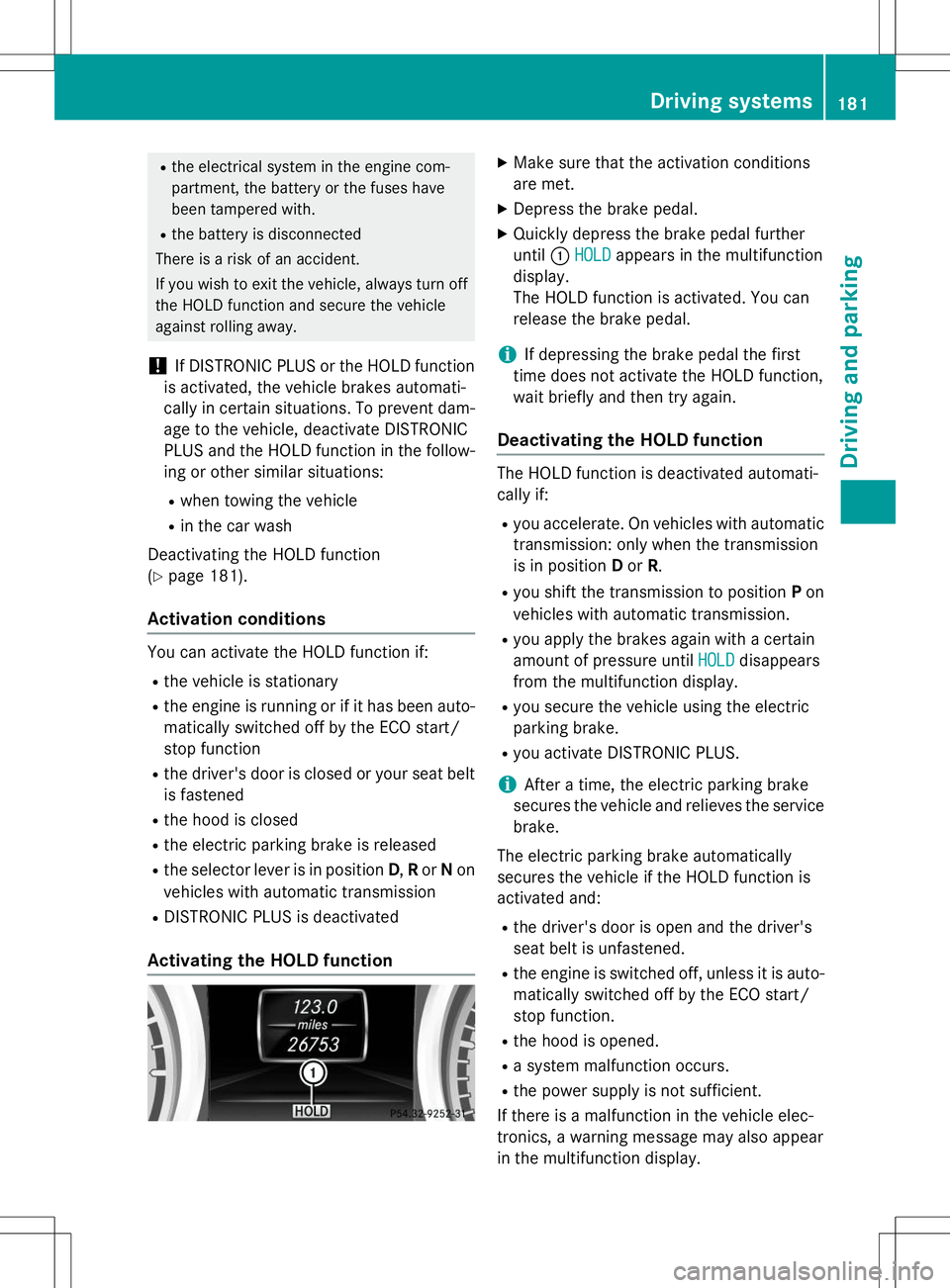
Activating the HOLD function
XMake sure that the activation conditions
are met.
X Depress the brake pedal.
X Quickly depress the brake pedal further
until :
HOLDappears in the multifunction
display.
The HOLD function is activated. You can
release the brake pedal.
iIf depressing the brake pedal the first
time does not activate the HOLD function,
wait briefly and then try again.
Deactivating the HOLD function
The HOLD function is deactivated automati-
cally if: R you accelerate. On vehicles with automatic
transmission: only when the transmission
is in position Dor R.
R you shift the transmission to position Pon
vehicles with automatic transmission.
R you apply the brakes again with a certain
amount of pressure until
HOLDdisappears
from the multifunction display.
R you secure the vehicle using the electric
parking brake.
R you activate DISTRONIC PLUS.
iAfter a time, the electric parking brake
secures the vehicle and relieves the service
brake.
The electric parking brake automatically
secures the vehicle if the HOLD function is
activated and: R the driver's door is open and the driver's
seat belt is unfastened.
R the engine is switched off, unless it is auto-
matically switched off by the ECO start/
stop function.
R the hood is opened.
R a system malfunction occurs.
R the power supply is not sufficient.
If there is a malfunction in the vehicle elec-
tronics, a warning message may also appear
in the multifunction display.
Driving systems181
Driving an d parking
Z
Page 265 of 358
Your attention must always be focused on thetraffic conditions. Only use the cigarette
lighter when road and traffic conditions per-
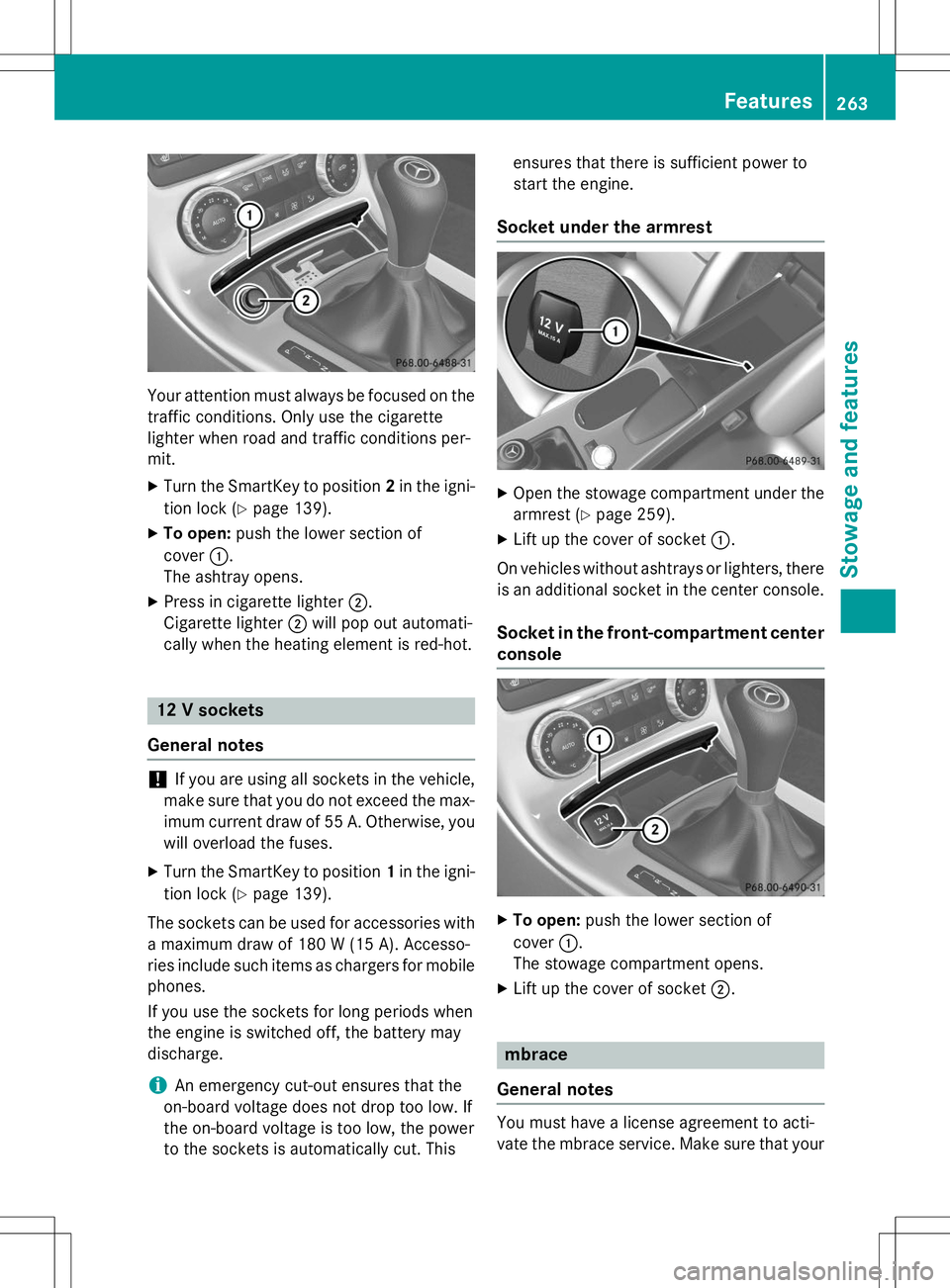
mit. X Turn the SmartKey to position 2in the igni-
tion lock ( Ypage 139).
X To open: push the lower section of
cover :.
The ashtray opens.
X Press in cigarette lighter ;.
Cigarette lighter ;will pop out automati-
cally when the heating element is red-hot.
12 V sockets
General notes
!If you are using all sockets in the vehicle,
make sure that you do not exceed the max- imum current draw of 55 A. Otherwise, you
will overload the fuses.
X Turn the SmartKey to position 1in the igni-
tion lock ( Ypage 139).
The sockets can be used for accessories with a maximum draw of 180 W (15 A). Accesso-
ries include such items as chargers for mobile
phones.
If you use the sockets for long periods when
the engine is switched off, the battery may
discharge.
iAn emergency cut-out ensures that the
on-board voltage does not drop too low. If
the on-board voltage is too low, the power
to the sockets is automatically cut. This ensures that there is sufficient power to
start the engine.
Socket under the armrest
X
Open the stowage compartment under the
armrest ( Ypage 259).
X Lift up the cover of socket :.
On vehicles without ashtrays or lighters, there
is an additional socket in the center console.
Socket in the front-compartment center
console
X To open: push the lower section of
cover :.
The stowage compartment opens.
X Lift up the cover of socket ;.
mbrace
General notes
You must have a license agreement to acti-
vate the mbrace service. Make sure that your
Features263
Stowage and features
Z
Page 295 of 358
Useful information............................294
Where will I find...? ...........................294
Flat tire .............................................. 295
Battery (vehicle) ................................ 299
Jump-starting .................................... 303
Towing and tow-starting ..................305
Fuses .................................................. 308
293
Roadside Assistance
Page 296 of 358
Useful information
iThis Operator's Manual describes all
models and all standard and optional equip- ment of your vehicle available at the time of
publication of the Operator's Manual.
Country-specific differences are possible.
Please note that your vehicle may not be
equipped with all features described. This
also applies to safety-related systems and
functions.
iRead the information on qualified special-
ist workshops ( Ypage 25).
Where will I find...?
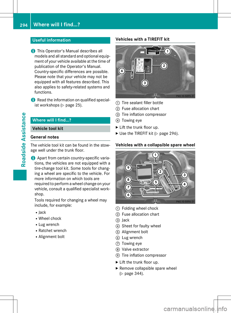
Vehicle tool kit
General notes
The vehicle tool kit can be found in the stow- age well under the trunk floor.
iApart from certain country-specific varia-
tions, the vehicles are not equipped with a
tire-change tool kit. Some tools for chang-
ing a wheel are specific to the vehicle. For
more information on which tools are
required to perform a wheel change on your
vehicle, consult a qualified specialist work-shop.
Tools required for changing a wheel may
include, for example:
R Jack
R Wheel chock
R Lug wrench
R Ratchet wrench
R Alignment bolt
Vehicles with a TIREFIT kit
:Tire sealant filler bottle
;Fuse allocation chart
=Tire inflation compressor
?Towing eye
X Lift the trunk floor up.
X Use the TIREFIT kit ( Ypage 296).
Vehicles with a collapsible spare wheel
:Folding wheel chock
;Fuse allocation chart
=Jack
?Sheet for faulty wheel
AAlignment bolt
BLug wrench
CTowing eye
DValve extractor
ETire inflation compressor
X Lift the trunk floor up.
X Remove collapsible spare wheel (Y page 344).
294Where will I find...?
Roadside Assistance
Page 310 of 358
Before tow-starting:R the battery must be connected
R the engine must be cold
R the exhaust system must have cooled down
When tow-starting, it is important that you
observe the safety instructions ( Ypage 305).
X Switch on the hazard warning lamps(Y page 111).
X Install the towing eye ( Ypage 306).
X Secure the rigid towing bar or the towing
rope.
X Depress and hold the brake pedal.
X Turn the SmartKey to position 2in the igni-
tion lock.
X Depress the clutch pedal fully, engage sec-
ond gear and keep the clutch pedal
depressed.
X Release the brake pedal.
X Tow-start the vehicle.
X Release the clutch pedal slowly; do not
depress the accelerator pedal while doingso.
X As soon as the engine starts, depress the
clutch pedal immediately and shift to neu-
tral.
X Stop at a suitable place, in accordance with
the traffic conditions.
X Depress the parking brake.
X Remove the rigid towing bar or towing rope.
X Remove the towing eye ( Ypage 306).
X Switch off the hazard warning lamps.
Fuses
Important safety notes
GWARNING
If you manipulate or bridge a faulty fuse or if
you replace it with a fuse with a higher amper-
age, the electric cables could be overloaded.
This could result in a fire. There is a risk of an
accident and injury.
Always replace faulty fuses with the specified new fuses having the correct amperage.
!Only use fuses that have been approved
for Mercedes-Benz vehicles and which
have the correct fuse rating for the system
concerned. Otherwise, components or sys-
tems could be damaged.
The fuses in your vehicle serve to close down faulty circuits. If a fuse blows, all the compo- nents on the circuit and their functions stop
operating.
Blown fuses must be replaced with fuses of
the same rating, which you can recognize by
the color and value. The fuse ratings are listed
in the fuse allocation chart.
If a newly inserted fuse also blows, have the
cause traced and rectified at a qualified spe-
cialist workshop, e.g. an authorized
Mercedes-Benz Center.
Before changing a fuse
X Secure the vehicle against rolling away (Y page 161).
X Switch off all electrical consumers.
X Turn the SmartKey to position 0in the igni-
tion lock and remove it ( Ypage 139).
or
X On vehicles with KEYLESS-GO, make sure
the ignition is switched off ( Ypage 140).
All indicator lamps in the instrument cluster
must be off.
The fuses are located in various fuse boxes:
R Fuse box in the engine compartment on the
left-hand side of the vehicle, when viewed
in the direction of travel
R Fuse box in the trunk
The fuse allocation chart is located in the
vehicle tool kit in the stowage compartment
under the trunk floor ( Ypage 294).
308Fuses
Roadside Assistance
Page 311 of 358
Fuse box in the engine compartment
iObserve the "Important safety notes" sec-
tion ( Ypage 308).
GWARNING
When the hood is open and the windshield
wipers are set in motion, you can be injured by
the wiper linkage. There is a risk of injury.
Always switch off the windshield wipers and
the ignition before opening the hood.
!Make sure that no moisture can enter the
fuse box when the cover is open.
!When closing the cover, make sure that it
is lying correctly on the fuse box. Moisture
seeping in or dirt could otherwise impair
the operation of the fuses.
X Make sure that the windshield wipers are
turned off.
X Open the hood.
X Use a dry cloth to remove any moisture
from the fuse box.
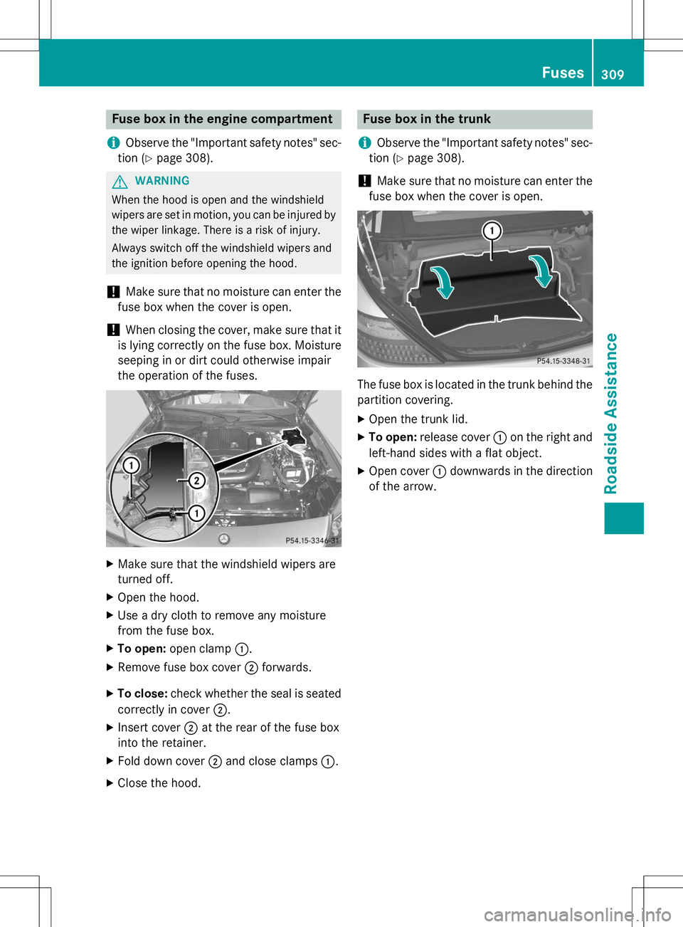
X To open: open clamp :.
X Remove fuse box cover ;forwards.
X To close: check whether the seal is seated
correctly in cover ;.
X Insert cover ;at the rear of the fuse box
into the retainer.
X Fold down cover ;and close clamps :.
X Close the hood.
Fuse box in the trunk
iObserve the "Important safety notes" sec-
tion ( Ypage 308).
!Make sure that no moisture can enter the
fuse box when the cover is open.
The fuse box is located in the trunk behind the
partition covering. X Open the trunk lid.
X To open: release cover :on the right and
left-hand sides with a flat object.
X Open cover :downwards in the direction
of the arrow.
Fuses309
Roadside Assistance
Z